Classification of Fractures and Dislocations
JONATHAN LABOVITZ, FRANCIS CHAN, AKSONE NOUVONG, AND ROBERT A. CHRISTMAN
Fracture classifications are used frequently in practice and clinical research. The goal and purpose of classification systems should provide a language for communication between physicians, to simplify the complexity of fractures, and guide treatment and/or provide prognostic value. When fracture classifications are used to describe particular fractures, it enhances communication and is a beneficial educational resource. Classifications, which only describe patterns, do not rely on a high level of validity or reproducibility, whereas classifications serving to guide treatment or forecast clinical outcomes require a high level of validity and reproducibility.1
Oftentimes, fracture classifications are plagued by fair or poor interobserver reliability and intraobserver reproducibility. Interobserver reliability references the level of agreement between different observers classifying the same fracture. Intraobserver reproducibility references the level of agreement of a single observer classifying a particular fracture on separate occasions.2 A number of classifications used in foot and ankle trauma fall into the category of low validity and reproducibility. Additionally, there is a paucity of literature evaluating the many classifications in use. The causative factors of the low interobserver and intraobserver reliability are undetermined in most cases. The quality of the bone can be one cause, since osteopenia can challenge one’s ability to identify the fracture lines. However, this characteristic is not included in classification systems despite its potential effect on treatment and outcomes. The quality of radiographs and the use of advanced imaging modalities have not been shown to affect the outcomes when measuring reliability of classification systems. It is important to note that many of the studies have used a variety of methodologies, potentially skewing the reliability when comparing the literature.1
Currently, fracture classifications are best used as descriptive means of communicating. In general, the literature is unclear as to the value of classifications for guiding treatment. In addition, the literature seems to refute that classifications should be used to forecast patient outcomes, especially because of the low interobserver reliability and the validity and reproducibility remains in question.1 Despite the low interobserver and intraobserver reliability, most classification systems have been found to have good reliability in characterizing the least and the most severe injuries. These are the injuries that usually result in the best and worst outcomes, respectively. Meanwhile the injuries with moderate severity are most affected by the low reliability of the classification systems when predicting outcomes. With this in mind, classifications continue to be used for all of the intended uses, including guiding treatment and predicting outcomes.
DIGITAL FRACTURE
Digital fractures tend to be one of the most common fractures observed. The incidence has been reported to be 14 per 10,000 cases in the emergency room with a greater occurrence in males (1.6:1). Proximal phalanx fractures occur more often than fractures of either the middle or distal phalanx, with the hallux proximal phalanx being the most commonly fractured phalanx in the foot (Figure 16-1). However, lesser digits fracture nearly four times more than hallux fractures.3,4
Fracture severity depends on the magnitude and direction of the traumatic force. The most frequent direct trauma is a crush injury, caused by dropping a heavy object on the toe (Figure 16-2); this is the most common cause of middle and distal phalangeal fracture. Direct trauma is also associated with comminution. This fracture mechanism potentially exhibits displacement in the sagittal or transverse planes. When subungual hematoma occurs after a crush injury, it is important to clinically evaluate the nail bed since there is a higher incidence of open digital fractures with this presentation.
Indirect trauma is caused by an event applying external forces to the digit while acting distant to the fracture site, such as stubbing a toe against a fixed object.5 The most common example is called a “nightwalker’s fracture,” which occurs when the fifth toe is struck against a bedpost causing an abductory force (Figure 16-3). Despite the frequency of fifth toe stubbing, indirect trauma most frequently affects the hallux. The most common mechanism is a hyperextension or hyperflexion injury that causes a sagittal plane fracture. Meanwhile, the indirect abductory force mechanism of the nightwalker’s fracture results in a transverse or a short oblique fracture of the proximal phalanx base in the transverse plane. Either fracture pattern can have intra-articular extension involving the metatarsal–phalangeal joint or the interphalangeal joint. Spiral fractures also occur in the lesser digits secondary to indirect trauma.6 This same mechanism also results in interphalangeal dislocation, albeit an extremely rare injury.
Indirect fractures while barefoot are unique compared to those occurring while wearing shoe gear. Prognostic factors such as open fractures or dislocations, which are commonly associated with more severe digital fractures when barefoot, have been refuted since they are based on small population size and found to have minimal effect on larger samples.7
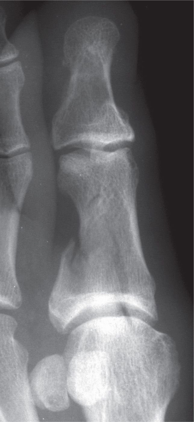
FIGURE 16-1. Displaced intra-articular fracture of the hallux proximal phalanx base (medial oblique view).
Clinically, digital fractures present with pain and edema, while ecchymosis and gross malalignment may also be seen. Displacement is most frequently observed with indirect trauma due to the likely angular force applied to the toe during the traumatic event. However, 10% to 25% of digital fractures present without pain or with only minimal symptoms.8
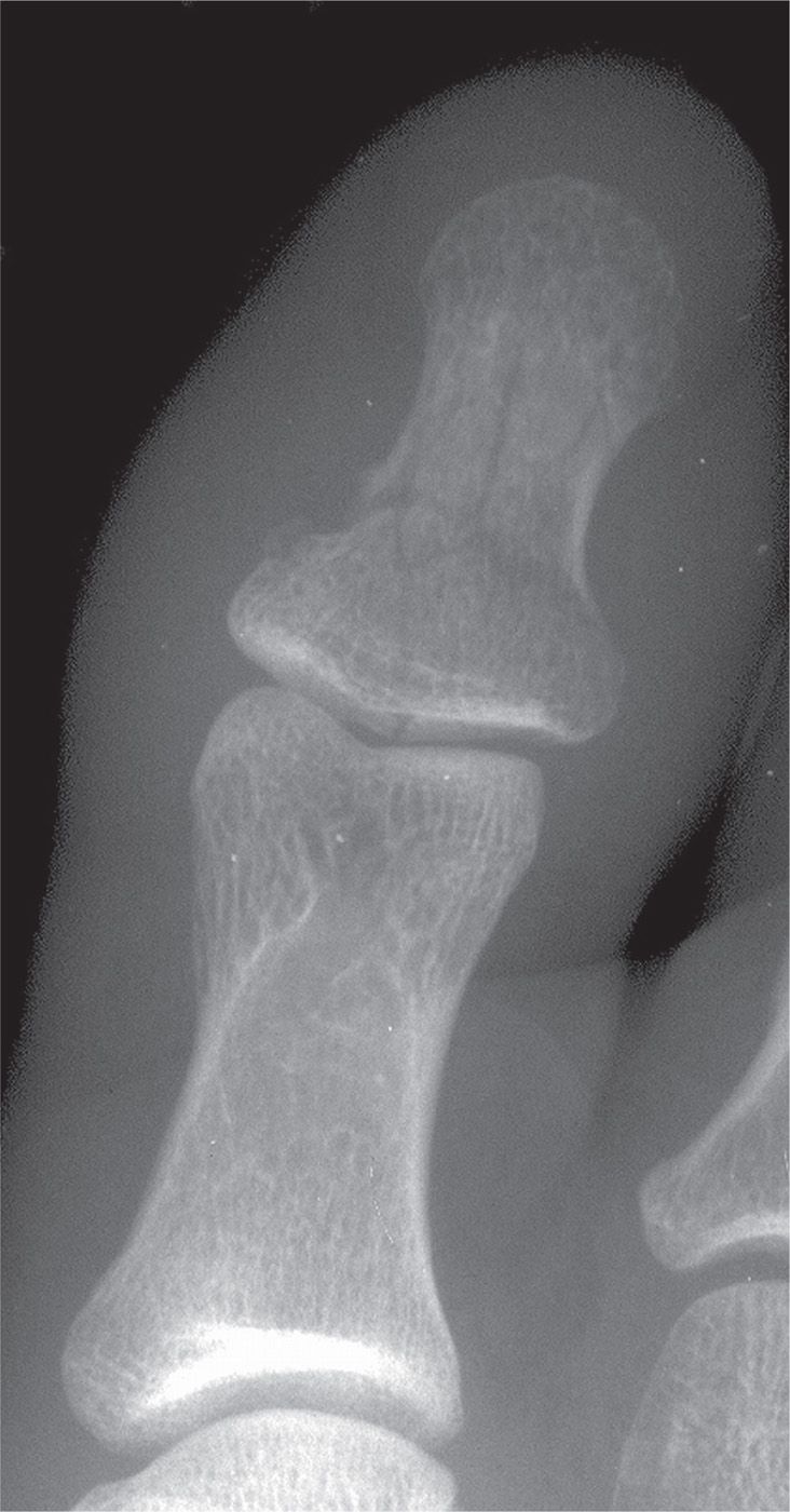
FIGURE 16-2. Comminuted fracture of the hallux distal phalanx (dorsoplantar view).
Dorsoplantar (anteroposterior), medial oblique, and lateral oblique views are necessary to properly diagnose a lesser digit fracture. The lateral view is not as beneficial secondary to the significant overlap of the digits. However, the lateral view may be useful for some fractures involving the hallux, especially if the hallux can be elevated to minimize superimposition.
Digital fractures are typically treated with simple immobilization of the digit. When subluxation occurs, closed reduction is usually sufficient. It has been suggested that as long as clinical alignment of the toe is satisfactory, then true osseous alignment is irrelevant, as the functional outcome will be satisfactory.9 Telescoping fractures with long oblique and spiral fracture patterns and intra-articular fragment subluxation require open reduction and internal fixation.
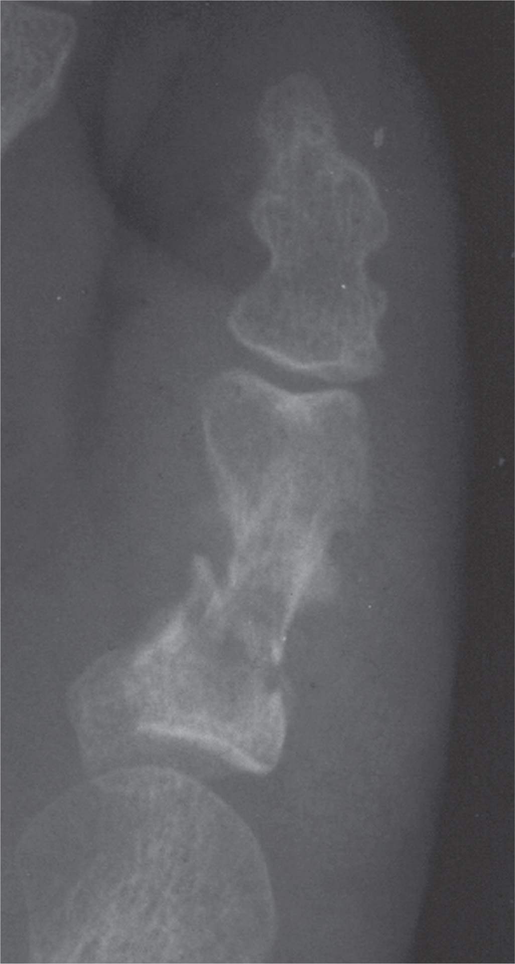
FIGURE 16-3. Oblique fracture of fifth toe proximal phalangeal shaft; the distal segment is mildly displaced and angulated laterally (dorsoplantar view). Periostitis is also evident.
SESAMOID FRACTURE
Different types of sesamoid fractures have been described. Excessive chronic forces applied to the sesamoid complex can cause stress fracture. The typical force during stance is 50% of body weight; up to 300% of body weight is applied during propulsion.10 A cavus foot structure can exacerbate the extent of this force on the sesamoids causing a fatigue fracture; an insufficiency stress fracture can occur if the sesamoid is pathologic. Stress fractures frequently lack an inciting event and there is an insidious onset of symptoms.
Acute forces can cause avulsion fracture, fracture with or without subluxation or dislocation, or diastasis of a bipartite sesamoid. A sagittal plane injury that crushes a sesamoid between the supportive ground surface and the first metatarsal head is the most common acute force causing a fracture. The risk of fracture increases with forced dorsiflexion of the hallux, which increases the pressure on the sesamoid complex, and hyperflexion injury of the first metatarsophalangeal joint. The tibial sesamoid is fractured more often than the fibular sesamoid because it is larger, longer, and located directly plantar to the metatarsal head.11 This location increases the amount of weight-bearing force borne by the tibial sesamoid compared to the fibular sesamoid.
If sesamoid fracture is clinically suspected, a radiographic study should be obtained. In addition to the dorsoplantar view, the medial oblique view is helpful in assessing both sesamoids, and a lateral oblique view aids in evaluating the tibial sesamoid. The sesamoid axial view is also beneficial (Figure 16-4); however, it is not always possible to isolate the sesamoids when there is acute pain. A bipartite sesamoid may be difficult to differentiate from a sesamoid fracture, and both have a higher prevalence in the tibial sesamoid. Generally speaking, the bipartite sesamoid has rounded, more well-defined or sclerotic cortical margins compared to the irregular, jagged edges of a fracture. Also, the summated size of the bipartite sesamoid is generally larger than the typical sesamoid. Meanwhile, the fracture is typically oriented transversely or is comminuted. When oriented longitudinally, the fracture line has a large gap compared to the bipartite sesamoid. The fracture may also present with unequal separation of fragments and periosteal bone formation, depending on the healing progress. Should radiographs be inconclusive, the absence of similar findings on contralateral radiographs may be helpful since bipartite sesamoids may occur bilaterally. Bone scintigraphy, computed tomography (CT), and magnetic resonance imaging (MRI) have also been used in cases of equivocal radiographs. Bone scintigraphy will demonstrate increased uptake on all three phases. The sagittal and coronal CT views are best for detecting sesamoid fractures. MRI demonstrates low signal intensity on T1-weighted images and high signal intensity on T2-weighted images at the fracture site.
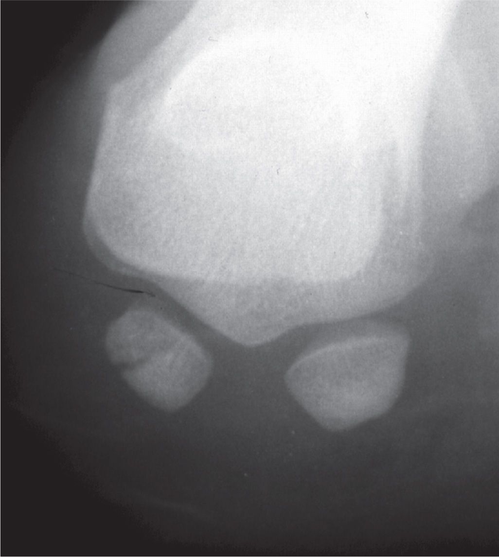
FIGURE 16-4. Fibular sesamoid fracture, sesamoid axial view.
Sesamoid fracture healing is complicated by continued weight bearing and impaired vascular supply. Delayed unions and nonunions should be considered and assessed clinically and with radiography. Avascular necrosis (AVN) is a less common complication; it appears to affect the tibial and fibular sesamoids equally, but slightly more in women than in men. In the presence of AVN, radiographs may be normal for at least six months before demonstrating other features associated with osteonecrosis (osteopenia, fragmentation, and eventually increased density and deformity). MRI imaging shows decreased signal intensity on T1-weighted images and serpiginous low and high signal areas on T2-weighted images; the latter usually appear as two concentric bands, sometimes referred to as the double-line sign.
FIRST METATARSOPHALANGEAL JOINT DISLOCATION
Dislocation of the first metatarsophalangeal joint is a rare injury. Few studies have been completed, and sporadic case reports are littered throughout the literature. In over 10,000 patients at the Orthopedics Clinic of Athens University over a 10-year period, only four dorsal dislocations of the first metatarsophalangeal joint were identified.12 The classification of these injuries, developed by Jahss,13 was based on published case reports and only two of his own cases out of approximately 25,000 patients over 18 years of patient care (Table 16-1).
The uniqueness of this injury is rooted in the complex stability of the first metatarsophalangeal articulation. The joint is comprised of a concave and corresponding convex surface surrounded by a joint capsule and collateral ligaments. The fibrocartilaginous plantar plate provides a strong reinforcement of the capsule. Additional stability is derived from the sesamoid complex, including the thick intersesamoidal ligament and the conjoint tendon of the flexor hallucis brevis.
Clinically, first metatarsophalangeal joint dislocation presents with the proximal phalanx lying on top of the dorsal first metatarsal neck; the first metatarsophalangeal joint is hyperextended and the hallux interphalangeal joint flexed. The hallux appears shortened; the extensor tendons are relaxed, and the first metatarsal head is prominent plantarly.
| Jahss13 Classification of First Metatarsal-Phalangeal Joint Dislocations |
Type | Description |
I | Dorsal dislocation of the hallux secondary to plantar plate rupture |
II-A | Dorsal dislocation of the hallux with intersesamoidal ligament rupture |
II-B | Dorsal dislocation of the hallux with transverse sesamoid fracture |
II-Ca | Dorsal dislocation of the hallux with intersesamoidal ligament rupture and tibial or fibular sesamoid avulsion fracture (combination of II-A and II-B) |
IIIb | Rupture of both conjoined tendons with intact sesamoids and plantar plate |
aModification to original classification by Copeland and Kanat.6
First metatarsophalangeal joint dislocation is the result of high-energy trauma, most commonly caused by a motor vehicle accident (MVA). Axial loading to the first metatarsophalangeal joint in a position of hyperextension results in dorsal dislocation. Medial, lateral, and plantar dislocations occur even less frequently; they too result from severe trauma associated with significant soft tissue damage. Injuries such as midfoot fracture, Lisfranc fracture–dislocation, and lesser metatarsal and phalangeal fractures are associated with dislocation of the first metatarsophalangeal joint secondary to the high-energy mechanism.14
Salamon et al.15 first described the pathologic anatomy of the dorsal dislocation. Jahss13 subsequently clarified the importance of the sesamoid complex and noted the need for plantar plate rupture to allow for the dorsal displacement of the phalanx on the metatarsal head. Jahss originally classified the injury as two types based on the anatomical structure injured (Table 16-1). Type I involves intact sesamoids and intersesamoidal ligament (Figure 16-5). The dorsiflexory force ruptures the plantar joint capsule and the metatarsal head becomes wedged within the rupture. The metatarsal is further locked into place by the overriding proximal phalanx and sesamoids and the taut medial and lateral conjoined tendons, precluding closed reduction.
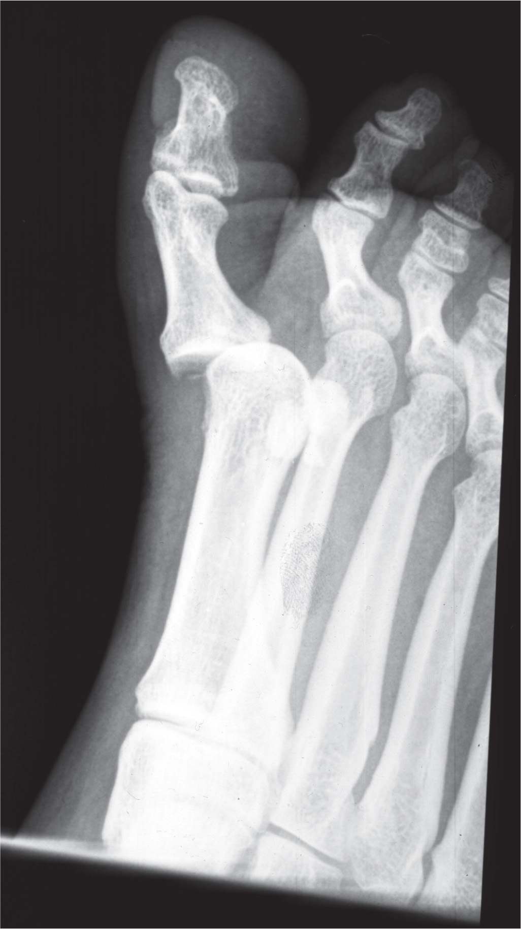
FIGURE 16-5. First metatarsophalangeal joint dislocation with dorsal and medial displacement of the hallux (medial oblique view).
As forced dorsiflexion continues secondary to increasing amounts of force, the intersesamoidal ligament ruptures, which Jahss classified as a type IIA injury. The ruptured intersesamoidal ligament creates a wide separation of the medial and lateral sesamoids radiographically. A type IIB injury defines the dorsal dislocation with a fractured sesamoid instead of intersesamoidal ligament disruption.13 Radiographs show a transverse sesamoid fracture, with the tibial sesamoid more commonly involved. No separation between the tibial and fibular sesamoids is observed radiographically.13 Later, Jahss13 modified the classification to include a type III dislocation whereby there is complete rupture of the conjoined tendons of the sesamoid complex while the plantar plate, intersesamoidal ligament, and sesamoids remain intact.
METATARSAL FRACTURE
Metatarsal fractures account for 5% of all fractures and 35% of all foot fractures, making them the most common foot fracture in adults. However, in addition to metatarsal fractures accounting for 61% of foot fractures in children, the frequency of involvement for each metatarsal also differs from the adult population.16–18 Metatarsal fractures are 10 times more common than tarsometatarsal fracture–dislocations. Usually as the result of direct trauma, indirect injuries occur when a transverse plane force is applied to a fixed forefoot on the weight-bearing surface. Stress fractures are also common mechanisms of injury. Fracture patterns are dependent on the extent of force causing the injury, as high-energy impacts frequently cause comminution. The more common low-energy injuries typically result in single fracture lines. The position of the foot and the direction of the force at the time of the impact also affect the fracture pattern. Most often, a transverse force creates a fracture line perpendicular to the long axis of the bone, and torsional forces create an oblique fracture or potentially a spiral fracture.
An anatomic classification is most commonly used, describing fractures by the metatarsal involved and the location within the metatarsal. The location of fracture is described as head, neck or subcapital, diaphyseal, and base. Fracture orientation in the head and neck typically presents as impaction, transverse, or oblique. Diaphyseal fractures involve transverse or oblique fractures; base fractures are frequently transverse in orientation.
In general, radiographs suffice for most metatarsal fractures. At least two views should be taken, oriented perpendicular to each other, although a third view is frequently necessary. The dorsoplantar (anteroposterior) view is beneficial for determining transverse plane subluxation, metatarsal length, and the metatarsal parabola. An oblique view helps to identify the fracture. The lateral view shows pure sagittal plane displacement and angulation; however, superimposition of the metatarsals in the lateral view complicates assessment. The sesamoid axial view may help with sagittal plane evaluation by displaying the inferior level of the metatarsal head relative to others.
Most metatarsal fractures, especially those caused by indirect, low-energy force, are nondisplaced; this is due to the significant surrounding soft tissues, especially at the metatarsal bases. As a result, the base of the metatarsal is locked in position, acting as a fulcrum for diaphyseal fractures. In some cases, these nondisplaced fractures require repeat radiographs since simple fracture is not always readily evident. When MRI is necessary to confirm the diagnosis, diaphyseal fractures appear as a hypointense cortical disruption on T1-weighted images with hyperintense bone marrow edema on T2-weighted and STIR (Short Tau Inversion Recovery) images. CT scans have also been recommended for base fractures due to the potential for tarsometatarsal joint injury.18
FIRST METATARSAL FRACTURE
The first metatarsal is the shortest, widest, and has the greatest strength of the five metatarsals. This is likely the primary reason that first metatarsal fractures are the least prevalent of the metatarsal fractures, accounting for only 1.5%. However, the first metatarsal bears twice the weight-bearing load of the lateral four metatarsals. Therefore, first metatarsal fractures are usually more significant, thus requiring more aggressive treatment. It is important to recognize the significantly higher incidence in pediatric patients, with reports as high as 19% of metatarsal fractures.18
Most often these fractures result from direct trauma, especially in industrial settings. First metatarsal head fractures can be intra-articular, and thus imaging must capture any joint involvement. In the case of equivocal radiographs, CT imaging helps provide adequate visualization of the fracture line and joint surface. Diaphyseal fractures are usually a long oblique or spiral fracture (Figure 16-6A). Proximal fractures are of the greatest concern secondary to the potential for sagittal plane deviation. Elevation of the first metatarsal alters the weight-bearing surface and can lead to altered gait and additional weight-bearing stress applied to the second metatarsal long term. However, isolated base fractures without Lisfranc fracture–dislocation are rare secondary to the strong tarsometatarsal joint complex (Figure 16-6B).
CENTRAL METATARSAL FRACTURE
Lesser metatarsal fractures can occur as the result of an acute injury or as a stress fracture (Figure 16-7). Metatarsal head and neck fractures are most common. Fractures of the metatarsal head may have an intra-articular component whereas the neck fracture is usually a transverse or short oblique pattern, thus without crossing the metaphysis and rarely intra-articular.
Subchondral fractures are rare and usually the result of overuse or pathologic fractures. The fracture is usually located in the central dorsal aspect of the metatarsal head and affects the second metatarsal in over 70% of cases.19 Since the subchondral fracture is commonly mistaken for Freiberg infraction or missed on radiographs, MRI may be indicated. Torriani et al.19 noted marrow edema to be present in 71% of cases, suggestive of early changes, while late findings consisting of metatarsal head collapse with subchondral sclerosis were observed in the remaining 29% of cases. Flattening of the metatarsal head was observed 57% of the time. Neck fractures, and occasionally head fractures, may involve some degree of displacement, with a tendency toward a plantar and lateral direction.18,19
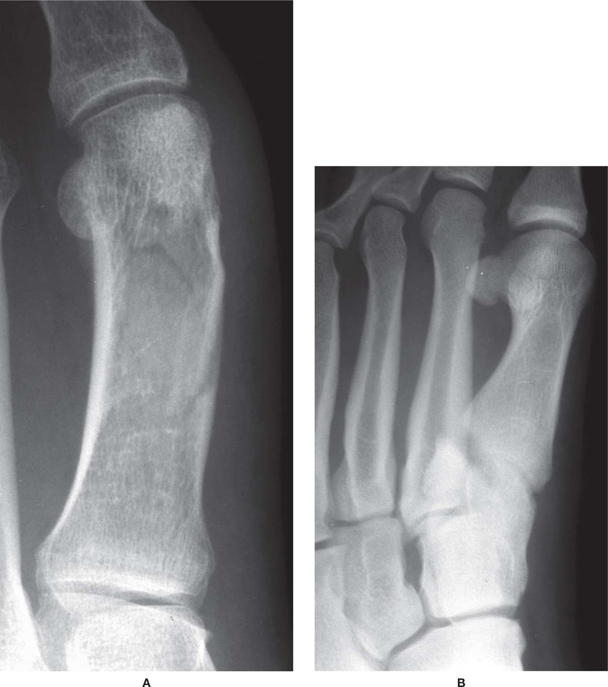
FIGURE 16-6. First metatarsal fracture. A: Diaphyseal. B: Avulsion of base at peroneus longus insertion.
Multiple metatarsals are often involved when there are head and neck fractures (Figure 16-8). Third metatarsal fracture also involves the second and/or fourth metatarsal in nearly two-thirds of cases. Therefore, it is important to carefully evaluate for involvement of other metatarsals when an isolated central metatarsal fracture is observed.20
Diaphyseal fractures are the result of direct trauma or a rotational force applied to the foot with the forefoot fixed on the ground. The fracture pattern is typically oblique or spiral when caused by rotational forces, although a transverse orientation and comminution can occur (Figure 16-9). Diaphyseal fractures are usually in the central or distal one-third of the second or third metatarsals. Shortening can occur, especially in the oblique fracture, secondary to the pull of intrinsic muscles. Sagittal plane displacement and shortening must be identified and adequately treated to prevent distortion of the metatarsal parabola and to prevent abnormal weight-bearing distribution. Unlike first and fifth metatarsal fractures, 3 to 4 mm of displacement in the transverse plane and less than or equal to 10° of angulation in fractures of the central metatarsals can be tolerated without long-term consequences.
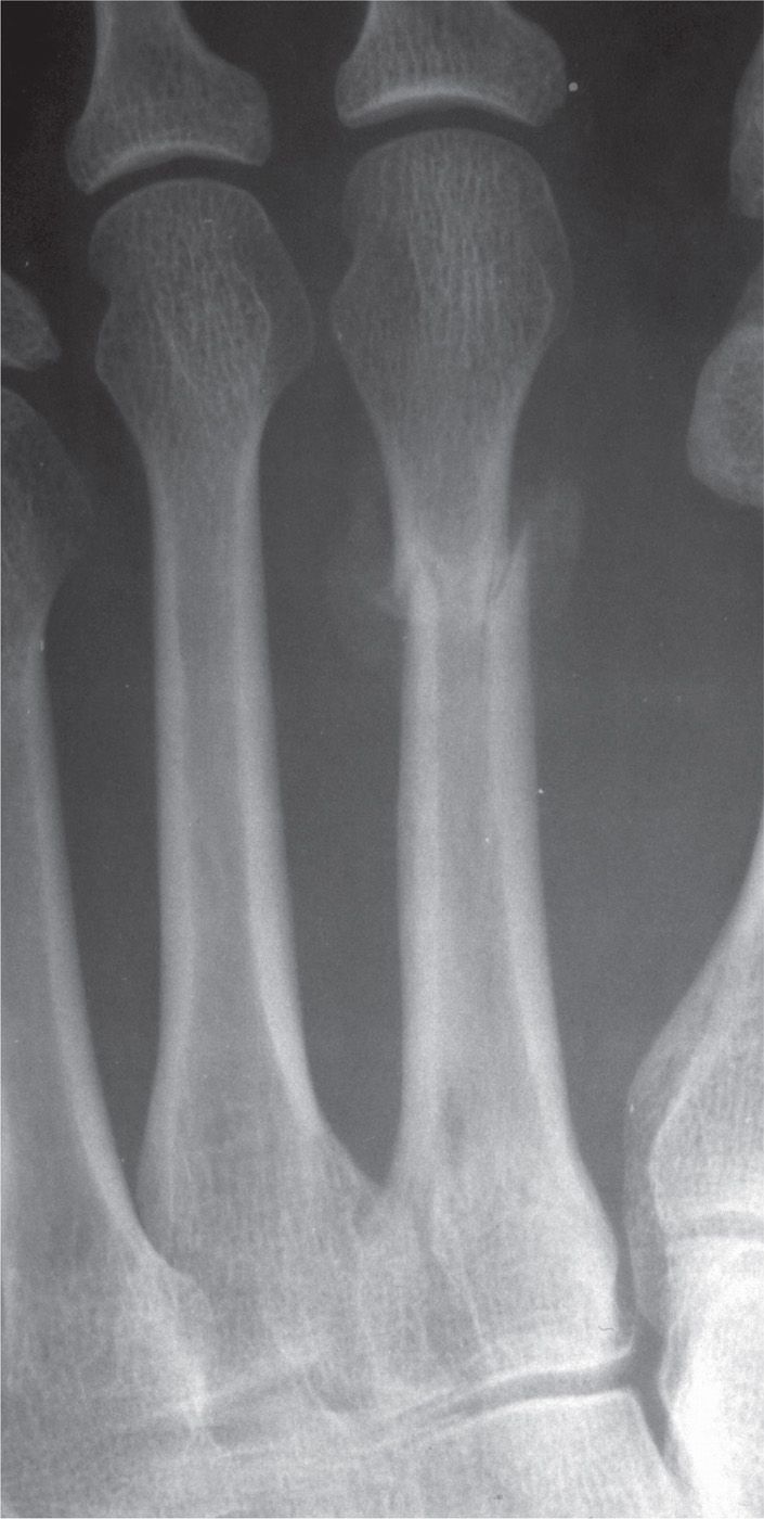
FIGURE 16-7. Cortical bone stress fracture, second metatarsal distal third diaphysis. Two-week postinjury radiograph demonstrates cortical break and periosteal reaction (type III stress fracture pattern).
Isolated base fracture of the central metatarsals occurs distal to the articular surface and is most often oriented transversely, thus remaining extra-articular. Many proximal metatarsal fractures, however, occur in conjunction with tarsometatarsal joint fracture–dislocations. Therefore, when a metatarsal base fracture is observed, assessment of the tarsometatarsal joint must be thorough to avoid misdiagnosing a more significant and debilitating injury. Often this assessment relies on additional diagnostic imaging studies that are discussed later in this chapter.
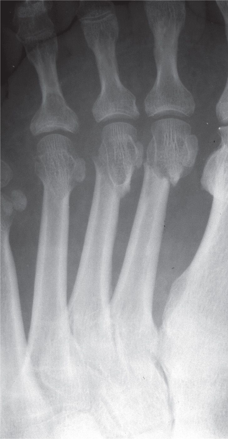
FIGURE 16-8. Fractures of the second, third, and fourth metatarsals.
FIFTH METATARSAL FRACTURE
Fractures of the fifth metatarsal are the most common foot fracture and involve approximately 45% to 70% of all metatarsal fractures.21 Men participating in athletic endeavors and people in the second through fifth decades of life are more common to sustain these injuries.22 Also, men are more likely to sustain these fractures, which are the most common metatarsal fractures in the industrial setting. However, women more commonly sustain fifth metatarsal fractures in the elderly. The fifth metatarsal is also the most commonly fractured metatarsal in the pediatric population. However, the increased incidence of first metatarsal fractures in children decreases the incidence of fifth metatarsal fractures to only 41% to 45% of metatarsal fractures.17,18 There are many classification systems for fifth metatarsal fractures, all of which are based on anatomic region, clinical symptoms, and/or radiographic findings. Despite the different anatomic locations, fifth metatarsal fractures, in general, are commonly associated with ankle, tarsal, and tarsometatarsal injuries.
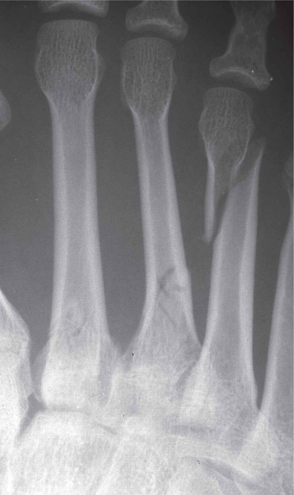
FIGURE 16-9. Oblique fracture, fourth metatarsal involving the distal third shaft, with medial displacement of the distal segment. There are also fractures of the second and third metatarsals; the third metatarsal fracture is in the proximal one-third diaphysis, and the second metatarsal fracture is at the junction between the proximal one-third diaphysis and the base.
Distal Fifth Metatarsal Fracture
Fractures of the fifth metatarsal head and neck are usually caused by direct trauma while distal diaphyseal fractures are often related to the indirect forces caused by traction from extrinsic musculature. Head and neck fractures of the fifth metatarsal rarely occur exclusively (Figure 16-10). Metatarsal head fractures are instead associated with multiple metatarsal fractures or other more proximal injuries such as ankle sprains. Head fractures are usually more challenging to identify radiographically due to impaction; displacement is infrequent. Transverse or long oblique fractures are common at the fifth metatarsal neck with a greater potential for shortening, transverse plane displacement, and angulation.
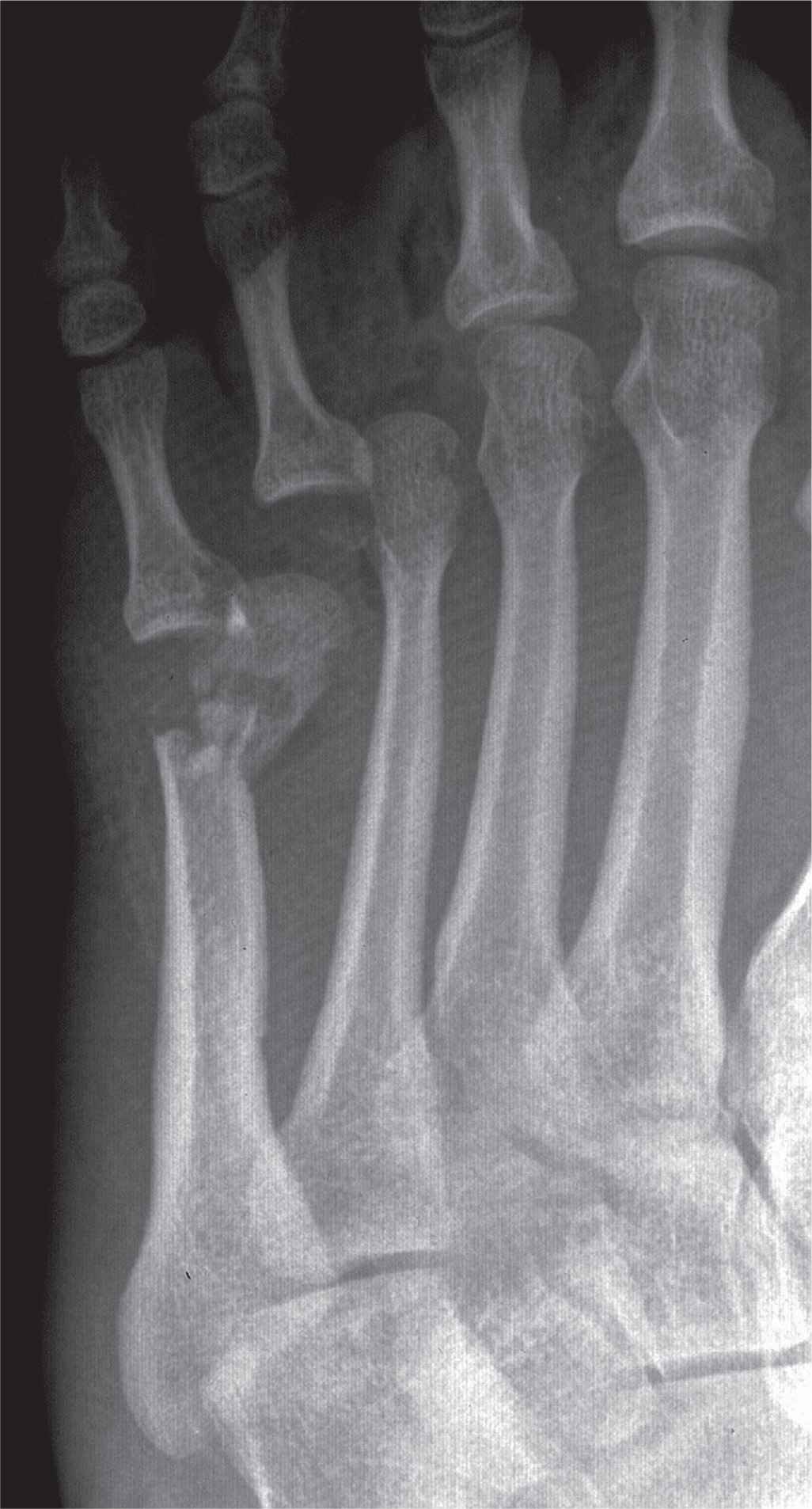
FIGURE 16-10. Transverse fracture of the fifth metatarsal head/neck demonstrating significant medial displacement and angulation of the distal segment. There is also an avulsion fracture and dislocation of the fourth metatarsophalangeal joint.
Diaphyseal Fracture
The distal diaphyseal fracture is usually an oblique or a short spiral fracture secondary to an inversion injury (Figure 16-11). Short oblique and transverse fractures have also been observed in the distal area of the metatarsal; significant force applied to the distal end of the metatarsal causes this fracture pattern. As the force extends proximally, a torque is applied since the metatarsal base is anchored by significant soft tissue attachments.23 The force causing the diaphyseal fracture frequently causes some comminution with a small butterfly fragment.
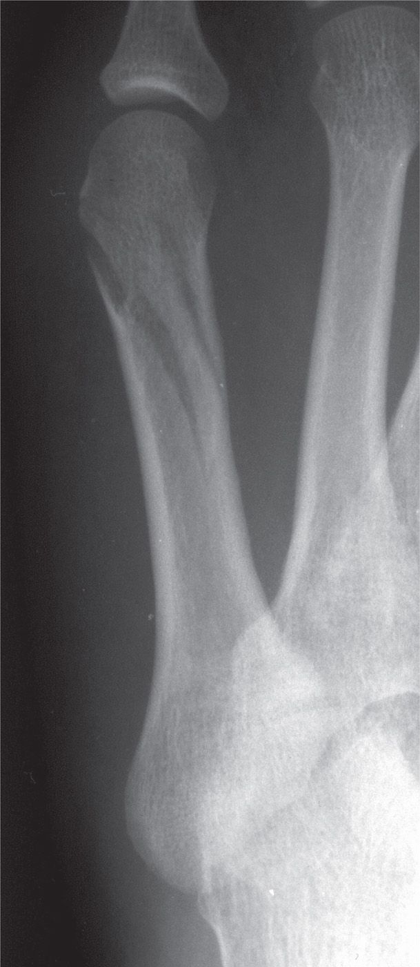
FIGURE 16-11. Oblique/spiral fifth metatarsal distal diaphyseal fracture.
Tuberosity Fracture
Avulsion fractures of the fifth metatarsal tuberosity are the most common fifth metatarsal fracture in both pediatric and adult populations. The fracture line is typically extra-articular but may extend into the calcaneocuboid joint. The tuberosity avulsion fracture occurs when there is a rapid inversion of the ankle and/or subtalar joint with a fixed forefoot. During this dynamic action, there is a pull of the lateral band of the plantar fascia. Further injury, consisting of rotation or displacement, occurs with the pull of the peroneus brevis.18,24,25 Tuberosity fractures, including the avulsion fracture, were classified in 1960 by Stewart26 and based on the anatomic location of the fracture (Table 16-2, Figure 16-12).
| Stewart26 Classification of Tuberosity Fractures of the Fifth Metatarsal |
Type | Fracture |
I | Extra-articular fracture between the metatarsal base and diaphysis |
II | Intra-articular fracture of the metatarsal base |
III | Avulsion fracture of the metatarsal base |
IV | Comminuted fracture with intra-articular extension |
Clinical symptoms of the avulsion fracture are pain, swelling, ecchymosis, and some loss of function. In addition to these symptoms, which are consistent with the clinical presentation of any fracture, one may observe a compensatory gait with excessive weight being placed on the medial aspect of the foot. It is important to assess other injuries as this fracture has been reported associated with ankle sprains and lateral malleolar fractures.
Radiographs that are usually beneficial in the diagnosis of the avulsion fracture include the dorsoplantar, lateral, and medial oblique foot views. However, up to 23% of avulsion fractures were missed with these standard views. Therefore, when clinical findings are suggestive of fracture despite negative standard foot radiographs, inclusion of an anteroposterior ankle view is indicated, since not all foot radiographs show the tuberosity while this ankle view is an additional view with good visualization of the tuberosity (Figure 16-13).27 In addition to confirming the diagnosis, radiographs also serve to assist with treatment planning. Tuberosity fractures displaced greater than 2 mm or involving more than 30% of the metatarsal-cuboid articulation should be treated operatively.
It is important to differentiate the tuberosity fracture from an accessory ossicle (os vesalianum) and the persistent fifth metatarsal apophysis. Os vesalianum is located adjacent to the tip of the fifth metatarsal tuberosity; the persistent fifth metatarsal apophysis includes the tuberosity (see Figures 6-52 and 6-53 in Chapter 6). In skeletally immature patients, the avulsion fracture must be differentiated from a secondary growth center. The apophysis appears around 8 years of age and fuses at an average age of 12 years in girls and 15 years in boys. The epiphyseal plate will typically be oriented parallel to the fifth metatarsal diaphysis, whereas the avulsion fracture is nearly perpendicular to the long axis of the diaphysis.
Jones Fracture and Proximal Diaphyseal Fracture
In 1902, Sir Robert Jones first described a proximal fifth metatarsal fracture that has become one of the most studied fractures of the foot. The popularity of the fracture centers on the high incidence in athletes. The high level of activity in athletes has affected fracture treatment, type of surgical fixation, time to return to activity, and the high complication rate with this injury. The original description was based on a series of five cases, including Jones’ own fracture sustained while dancing. This original case series involved fractures at two anatomic locations, the metaphyseal–diaphyseal junction and the proximal diaphysis of the fifth metatarsal.28,29 More recently, the Jones fracture has been strictly defined as a transverse fracture 1.5 cm distal to the fifth metatarsal tuberosity without distal extension beyond the fourth–fifth metatarsal articulation (Figure 16-12A).30 However, just as in Jones’s original case series, the strict definition of the fracture is often confused with proximal diaphyseal fractures due to the close proximity of the fractures anatomically.
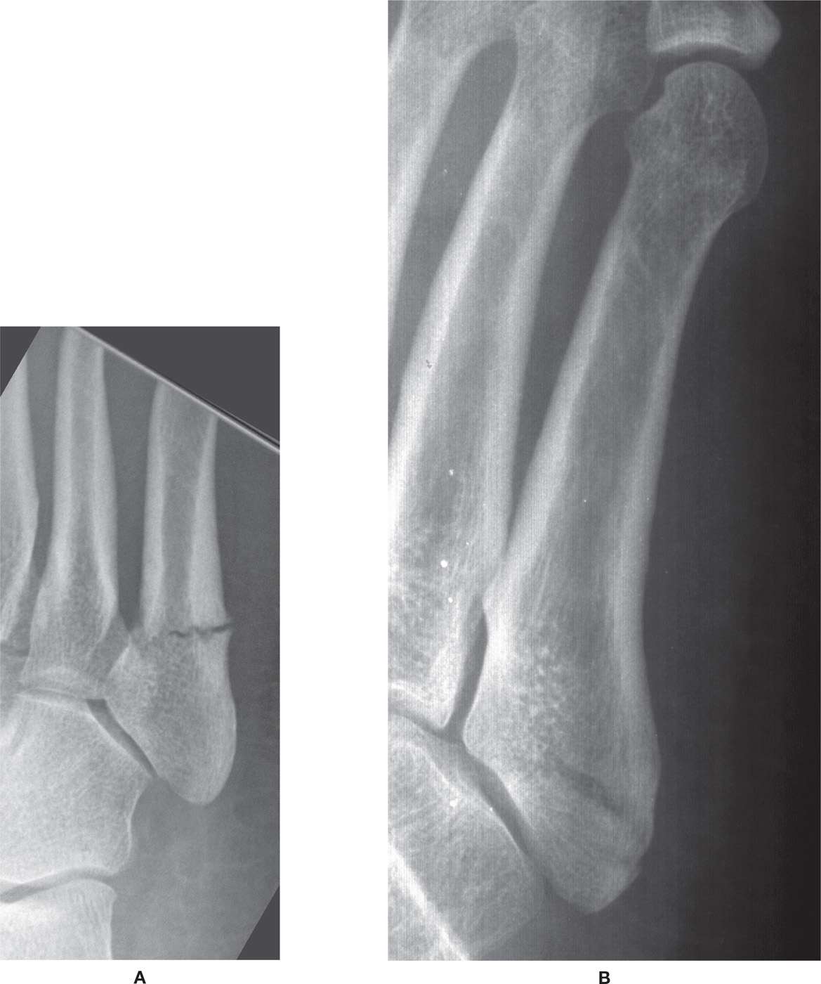
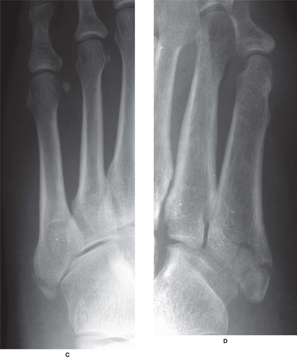
FIGURE 16-12. Fifth metatarsal tuberosity fractures, Stewart classification. A: Minimally displaced Jones fracture, medial oblique view (type I). B: Intra-articular fracture (type II). C: Avulsion of tip of tuberosity (type III). D: Comminuted fracture with intra-articular extension. (A: Courtesy of Diane Koshimune, DPM, Pomona, CA.)
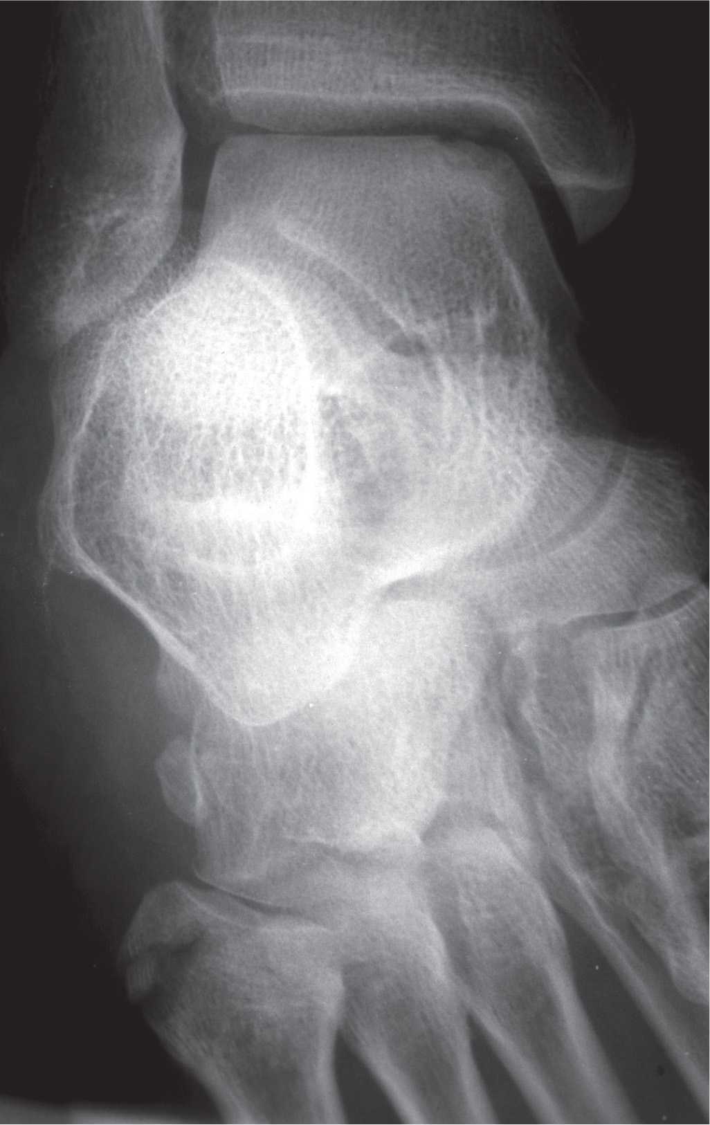
FIGURE 16-13. Fifth metatarsal tuberosity fracture demonstrated with a mortise ankle view.
Dameron and Lawrence classified proximal fifth metatarsal fractures by anatomic zones.30–32 While these two fractures are difficult to distinguish from each other due to their close proximity anatomically, the zones were developed to distinguish the Jones fracture from other proximal fifth metatarsal fractures having less variability in healing potential. Zone 1 includes tuberosity avulsion fractures. Fractures in zone 2 occur at the metaphyseal–diaphyseal junction (Jones fracture). Zone 3 fractures are distal to the metaphyseal–diaphyseal junction, which includes the proximal diaphyseal stress fracture adjacent and just distal to the fourth–fifth metatarsal articulation.
In addition to the anatomic difference between the Jones fracture and the proximal fifth metatarsal diaphyseal fracture, it was originally thought that they had different mechanisms of injury and different healing potential. The Jones fracture typically occurs with a vertical or abductory force on the fifth metatarsal base on a plantarflexed foot bearing weight along the lateral border.31,33 This force causes a transverse or obliquely oriented fracture line extending into the fourth–fifth metatarsal articulation, which may have some comminution medially. Meanwhile, chronic repetitive stress of intrinsic and extrinsic forces creates a fatigue fracture of the proximal diaphyseal fracture.30 Being of the same pathophysiology as other fatigue fractures, prodromal symptoms may be present clinically.
However, despite the differences in anatomic location and previously reported mechanism of injury, Chuckpaiwong et al.29 found no difference in the mechanism of injury, recovery time, or time to return to work between the Jones fracture and the proximal diaphyseal fracture. The only difference was time to return to sports, which was quicker in the operative patients of either fracture type. Contrary to numerous studies working to distinguish between the fractures and clarify the literature, this study29 led to the conclusion that there is no reason to distinguish between the fracture types.
Many emergency departments implement the Ottawa Ankle Rules when encountering proximal fifth metatarsal fractures. According to these rules, radiographs consisting of dorsoplantar, lateral, and medial oblique foot views should be ordered when there is pain with palpation of the fifth metatarsal. An additional anteroposterior ankle view should be taken if clinical findings suggest a fracture and foot radiographs are negative. A Jones fracture is usually more readily observed radiographically than the proximal diaphyseal fracture, which appears as a transverse or obliquely oriented fracture line, possibly with comminution medially. The proximal diaphyseal fracture appears as a stress fracture with a lucent, and possibly wider, fracture line. Additionally, the proximal diaphyseal fracture may also have a periosteal reaction and intramedullary sclerosis after 6 to 8 weeks.30 In the early phase of either fracture, technetium bone scintigraphy or MRI may be beneficial to confirm the clinical diagnosis. In light of the clinical difficulties with treatment of such fractures, MRI is also recommended if there is clinical suspicion despite negative radiographic views.
The Torg classification, which is most widely accepted, is based on the continuum of radiographic findings and the potential for prolonged healing time34 (Table 16-3); this manifests as delayed union and nonunion, which have a higher prevalence in these fractures (Figure 16-14). The Jones fracture occurring at the watershed area of the fifth metatarsal is the most often cited cause of the high complication rate. Biomechanically, the independent fifth ray range of motion and the dynamic traction by extrinsic muscles has also been implicated. The Torg classification scheme has become a guide in treatment strategy for Jones fractures and proximal fifth metatarsal diaphyseal fractures.
| Torg34 Classification for Proximal Fifth Metatarsal Fractures Based on the Continuum of Radiographic Findings and Potential Healing Complications |
Fracture Type | Radiographic Findings |
I | Narrow fracture line in the absence of intramedullary sclerosis |
II | Widening of the fracture line with intramedullary sclerosis |
III | Complete obliteration of the medullary canal with sclerotic bone formation |
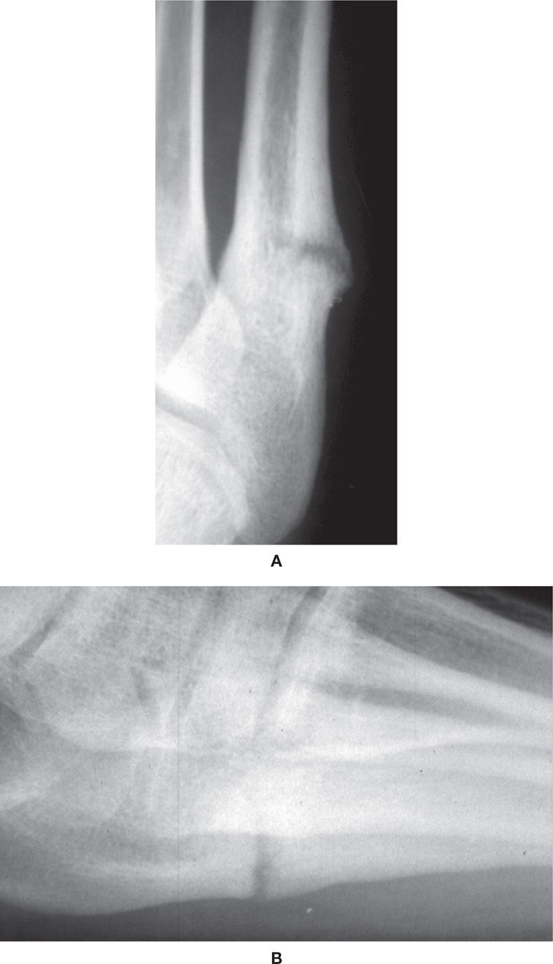
FIGURE 16-14. Delayed union/nonunion near fifth metatarsal base (Torg type II). A: Dorsoplantar view. B: Lateral view.
TARSOMETATARSAL FRACTURE–DISLOCATION
Tarsometatarsal joint (Lisfranc) fracture–dislocation is rare, occurring in 1 in 55,000 to 60,000 people annually, or approximately 0.2% of all fractures. The injury occurs 2 to 4 times more often in males. The low incidence of Lisfranc injuries is secondary to the strong anatomical structures that maintain the joint integrity, including the architecture of the joint itself. However, some have postulated that the true incidence is difficult to quantify and is likely underestimated due to the high rate of misdiagnosis.35,36
The unique shape of the bones and the joint contribute to the intrinsic joint stability. The wedge-shaped cuneiforms and the trapezoidal-shaped central metatarsal bases provide joint stability through an interlocking mechanism across the transverse arch and allow transmission of compressive forces to adjacent bones.37 Meanwhile, the second metatarsal base is recessed in relation to the first and third metatarsal bases. The depth of this mortise has been implicated as a risk factor for Lisfranc fracture–dislocation, with less depth along the articulation of the medial margin of the second metatarsal base and the medial cuneiform at greater risk. Peicha et al.38 implied that there is less risk of the injury with a deeper mortise since the greater joint surface may allow for a wider Lisfranc ligament, providing a stronger, more stable joint.
It has long been accepted that the supporting soft tissue has been integral in protecting this joint from injury as well. The interosseous and plantar ligaments provide much of the joint strength; the weaker dorsal ligaments, combined with the plantar apex of the wedge-shaped metatarsal bases, favor the commonly observed dorsal dislocation. However, interosseous ligaments only exist between the lesser metatarsals, with no such interosseous stability from ligaments connecting the first metatarsal with the four lateral metatarsals. Therefore, the obliquely oriented Lisfranc ligament exclusively secures the first and second rays by connecting the medial cuneiform base laterally to the second metatarsal base medially. The strength of the Lisfranc ligament is critical for intrinsic joint stability and is the reason for the lateral four metatarsals being displaced as a unit during tarsometatarsal fracture–dislocation.
The mechanism of injury has to be such that the strong anatomic architecture can be disrupted. An indirect axial force applied to a foot in hyperflexion causes increased tensile force across the convex dorsal surface of the metatarsals, resulting in dorsal dislocation. The other common mechanism is an indirect rotation force on the midfoot of a fixed foot as the body progresses over the foot position. Motorcycle accident and MVA account for the majority of indirect injuries. Falls from a height, equestrian accidents, stepping off a curb, and sports-related injuries are other commonly reported low-energy activities associated with tarsometatarsal joint fracture–dislocation. A direct crush injury can lead to a dorsal or a rare plantar dislocation dependent on the direction of the force applied and the position of the foot at the time of impact. Low-energy indirect forces account for approximately one-third of injuries, while high-energy events and direct forces account for two-thirds of fracture–dislocations.39
Patients with tarsometatarsal joint injuries present with significant pain, edema, and difficulty or inability to bear weight. However, subtle injuries are more frequent than expected, and mild pain when ambulating may be the only clinical finding in these cases. Ecchymosis in the plantar longitudinal arch, the “plantar ecchymosis sign,” is indicative of a tarsometatarsal joint injury while some consider this finding pathognomonic. Other findings may include pain with palpation or stress abduction of the tarsometatarsal joint and a shortened or widened appearance. Davies and Saxby40 described the “gap sign,” where there is a separation of the hallux and second digit and radiographic diastasis between the medial and middle cuneiform articulation with normal alignment of the first and second metatarsocuneiform joints. These findings are evident exclusively on the weight-bearing dorsoplantar radiographic examination. This sign is indicative of a dislocation involving diastasis of the medial and middle columns of the foot causing joint instability (Figure 16-15).40 Interposition of the tibialis anterior tendon between the cuneiforms has been observed when the same gap is reported radiographically.41 Since subtle injuries may have an absence of clinical findings, complicating the usual diagnostic process, clinical suspicion remains the most important examination tool.42
As in any acute trauma, radiography remains the primary imaging modality (Table 16-4). The standard initial images should be dorsoplantar, 30° medial oblique, and lateral foot views. The dorsoplantar view is best for viewing the first and second metatarsals; the medial oblique view is best for the lateral three metatarsals. Weight-bearing views are preferable, since this position applies the necessary stress across the joint to accurately depict the first and second ray diastasis that may not be evident in many low-energy injuries. However, weight-bearing radiographs are frequently difficult to obtain secondary to the acute pain preventing proper positioning. This decreases the chance to visualize the diastasis, thus yielding false-negative assessments.43–45
Foster and Foster46 defined the normal relationships between the metatarsal bases and their respective midtarsal articular surfaces to facilitate ease of diagnosing tarsometatarsal joint abnormalities (Table 16-5). The second metatarsal–intermediate cuneiform joint is the most consistently aligned articulation within the tarsometatarsal complex. The fourth metatarsocuboid articulation in the medial oblique view and the superior border of the first and second metatarsal and respective cuneiform articulation in the lateral view should be aligned. Other articulations within the joint complex are inconsistent due to osseous superimposition in radiographs.
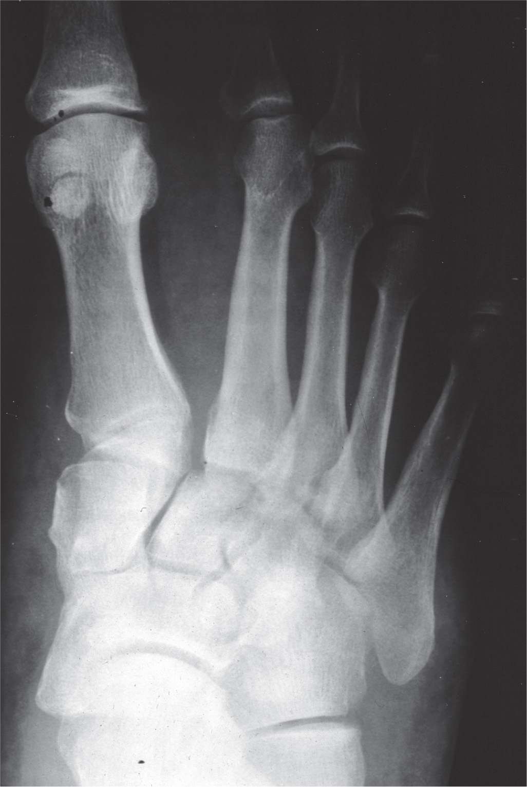
FIGURE 16-15. First and second ray diastasis with lateral displacement of second ray due to Lisfranc ligament rupture.
| Imaging Recommendations for Tarsometatarsal Joint Fracture–Dislocations |
Imaging Study | Type of Study | Recommended Use/Benefit |
Non–weight-bearing radiographs | Dorsoplantar, medial oblique, lateral | Initial test |
Weight-bearing radiographs | Dorsoplantar, medial oblique, lateral | Initial test or when non–weight-bearing films negative and high index of suspicion |
Stress abduction radiographs | With or without fluoroscopy under anesthesia |
|
CT scan | Multidetector with 3-D reconstruction | Improved sensitivity, visualization of subtle fractures and associated fractures, preoperative planning |
MR imaging | Oblique axial images for Lisfranc ligament and sagittal and coronal for other ligaments and osseous alignment | Best study for ligament evaluation; Good for bone marrow edema and subtle fractures |
Diastasis between the first and second metatarsal bases is the most common radiographic finding. The “fleck sign” represents an avulsion fracture caused by an intact Lisfranc ligament pulling a small bone fragment from its attachment at the second metatarsal base medially. This pathognomonic finding is observed in approximately 90% of cases.47 Joint instability is typically confirmed by a diastasis of greater than or equal to 2 mm or the “fleck sign.” A difference greater than 1 mm between the injured and uninjured foot is indicative of the injury. However, it is difficult to rely on 1 mm since the technical considerations of radiography likely limit the accuracy at this distance.48 Since a gap between the first and second metatarsals may be normal, Potter et al.48 concluded that weight-bearing bilateral radiographs are necessary to demonstrate findings consistent for disruption of the Lisfranc ligament; in that case, the injured and uninjured feet should demonstrate a difference of greater than or equal to 2 mm between the medial cuneiform and second metatarsal, and the second metatarsal–cuneiform joint is incongruent. Contralateral films are also important since up to 50% of normal non–weight-bearing films demonstrate a diastasis.44 Dorsal dislocations are seen on the lateral radiograph and usually involve dorsal displacement of the second metatarsal on the intermediate cuneiform.47 However, since a step-off between the second metatarsal and intermediate cuneiform of 4 mm has been observed in a normal foot, contralateral foot radiographs also enhance diagnostic accuracy for dorsal displacement.46
Subtle injuries are frequently encountered, leading to a missed diagnosis in 20% to 39% of cases.35,42,47,49 Accurate and timely diagnosis is necessary in order to reduce the risk of a poor functional outcome or prolonged disability (Figure 16-16). Spontaneous reduction and partial rupture of the Lisfranc ligament, commonly diagnosed as a midtarsal joint sprain, have been implicated as potential causes of the subtle nature of some presentations.44,50 Overlapping shadows, inappropriate positioning, and suboptimal exposure makes radiographic identification of anatomic landmarks and joint instability difficult.37,51 For example, one study noted that only 61% of Lisfranc injuries were detected radiographically. There was a false-negative rate of 19% for Lisfranc injuries compared to 13% for all injuries. The mean accuracy of Lisfranc injury detection was 92%.52 Despite these subtle injuries, Vuori and Aro49 found that the correct diagnosis could have been made in the majority of missed cases with careful inspection of initial radiographs coupled with clinical correlation. In an attempt to improve diagnostic accuracy of the subtle Lisfranc injury, Nunley and Vertullo44 developed a classification system using clinical findings, weight-bearing radiographs, and bone scintigraphy. However, based only on 13 patients, the classification has not been validated (Table 16-6).
A clinician should have a high index of suspicion for a tarsometatarsal joint fracture–dislocation when metatarsal base and isolated cuneiform and cuboid fractures are observed. Metatarsal fractures occur with frontal plane dislocations involving all metatarsals, presenting in 95% of tarsometatarsal injuries. The second metatarsal is most often associated with Lisfranc fracture–dislocations, whereas fifth metatarsal fractures are most common when no Lisfranc injury is sustained. Cuneiform fractures are also associated with Lisfranc fracture–dislocation as the force extends into the cuneiforms with the dislocation causing divergence between metatarsals. High-energy trauma may result in associated fractures of bones outside of the tarsometatarsal joint complex, such as the navicular, calcaneus, and talus (Figure 16-17).
| Radiographic Findings Consistent with Lisfranc Injury |
View | Finding |
Dorsoplantar | Diastasis between the first and second metatarsal bases • >2 mm on injured foot • >1 mm compared to uninjured contralateral foot Loss of alignment between • Medial base of the second metatarsal and the medial border of the middle cuneiform • Lateral base of the first metatarsal and the lateral border of the medial cuneiform “Fleck sign”—small avulsion fracture from the medial base of the second metatarsal caused by the Lisfranc ligament |
Medial oblique (30°) | Loss of alignment between the medial base of the fourth metatarsal and the medial border of the cuboid |
Lateral view | Loss of alignment of first and second metatarsals superior margin with corresponding cuneiforms Flattening of the longitudinal arch and/or loss of alignment between the plantar aspect of the fifth metatarsal and the medial cuneiform |
Adapted from Eleftheriou KI, Rosenfeld PF, Calder JDF. Lisfranc injuries: an update. Knee Surg Sports Traumatol Arthrosc. 2013;21:1434–1446; Foster SC, Foster RR. Lisfranc’s tarsometatarsal fracture-dislocation. Radiology. 1976;120(1):79–83.
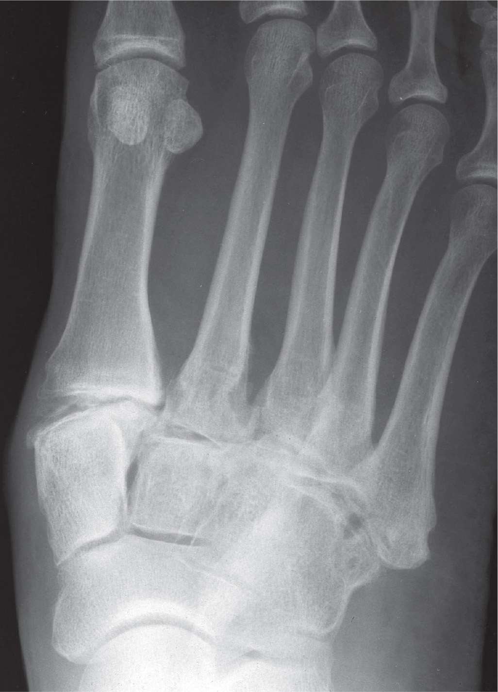
FIGURE 16-16. Posttraumatic arthritis secondary to Hardcastle type A lateralizing Lisfranc injury.
To assist with the diagnostic injury when equivocal radiographs are obtained, stress abduction views can be performed; this requires anesthesia because the technique causes pain. This test exacerbates the joint instability and diastasis due to the abductory force applied, thus recreating the fracture–dislocation. There is a 10% to 20% false-positive rate, which is likely because there is no standardized stress abduction technique; therefore, doubt in the validity and reliability of the test exists.43 However, CT scans provide enhanced images with less importance on patient positioning and without requiring painful manipulation of the acutely injured foot.42,50,53
The simplicity of patient positioning to optimize visualization and the lack of inducing further pain are the primary reasons that many experts prefer multiplanar reconstruction CT images for Lisfranc injuries, especially when clinical or radiographic assessment is difficult (Table 16-4). CT imaging is also easy to perform while providing enhanced anatomic detail free of superimposed structures in the midtarsus, thus improving sensitivity and diagnostic accuracy. Radiography has missed subtle 1 mm subluxations and most 2 mm subluxations, all of which were detected using CT imaging.54 Haapamaki et al.42 reported that radiographs are 25% to 33% sensitive for diagnosing midfoot fractures and 25% sensitive for diagnosing Lisfranc fracture–dislocations, with 24% false negatives. In addition, 35% of feet had occult fractures in other areas of the foot that were missed with radiography.
CT images also show the “fleck sign” and better delineate the extent of the fracture–dislocation, dorsal “step-off,” and other occult fractures and associated injuries, such as chondral and periarticular abnormalities. CT images also provide significantly more information helpful for preoperative planning.39,55–57 Leenen and van der Werken58 developed a classification system using CT images to assist in determining the appropriate treatment (Table 16-6). Grade I injuries were virtually nondisplaced, requiring immobilization, whereas grade II lesions were displaced less than 50% of the metatarsal diaphyseal width. These injuries were treated with open reduction internal fixation (ORIF), should closed reduction under general anesthesia fail. Meanwhile, ORIF was done for all grade III injuries, which represented those with total displacement.
However, some experts prefer MRI since it also enhances diagnostic accuracy compared to radiography and is better able to depict a diastasis compared to CT imaging.43,48,59,60 MRI is recommended for the subtle abnormality when ligamentous injury is suspected (Table 16-4). Enhanced anatomical detail is clearly evident in MRI, as this imaging technique is superior in depicting ligament abnormalities in the foot.60 More specifically, MRI is ideal for visualizing the Lisfranc ligament and injuries of the complex joint structure.48,60,61 Optimal visualization of the tarsometatarsal joint ligaments occurs in distinct anatomic planes (Table 16-7). However, MRI also allows for identification of non- or minimally displaced injuries and small avulsion fractures, which may be identified by the presence of bone marrow edema, when radiographs and CT images appear normal.56 Sensitivity is significantly greater than radiography, with MRI identifying disruption or a grade II sprain of the plantar bundle of Lisfranc ligament, which has a positive predictive value of 94% and a sensitivity and specificity for diagnosing tarsometatarsal joint instability of 94% and 75%, respectively.43
The most well-known classification schemes are based on the congruency and displacement of the metatarsal bases. Quenu and Kuss62 first classified the tarsometatarsal joint fracture–dislocation in 1909 (Figure 16-18). This scheme, based on frontal plane dislocations, classified the injury into homolateral, partial, and divergent dislocations. Using the Quenu and Kuss framework, Hardcastle et al.41 stratified the injury into a new classification to help guide treatment. This classification was based on dislocations occurring in all planes and consisted of total incongruity, partial incongruity, and divergent injuries. Partial incongruity injuries are subdivided into medial or lateral patterns. Divergent injuries were described as having partial or total incongruity, with the possibility of sagittal plane displacement.41 The most widely accepted classification is the Hardcastle classification with Myerson’s modification, which attempts to assist with treatment planning (Table 16-6, Figure 16-19). While neither of the earlier classification systems aid in treatment planning or prognosis, since they are based on the mechanism of injury, Myerson et al.63 modified the Hardcastle classification in an attempt to assist with treatment planning and provide prognostic value (Figure 16-20). However, the prognostic ability has been questioned due to a weak correlation with outcomes and low interobserver and intraobserver reliability.63 Overall, these classifications provide a good descriptive tool for Lisfranc fracture–dislocations, but the guidance in treatment and forecast of outcomes remain limited.
| Lisfranc Fracture–Dislocation Classifications |
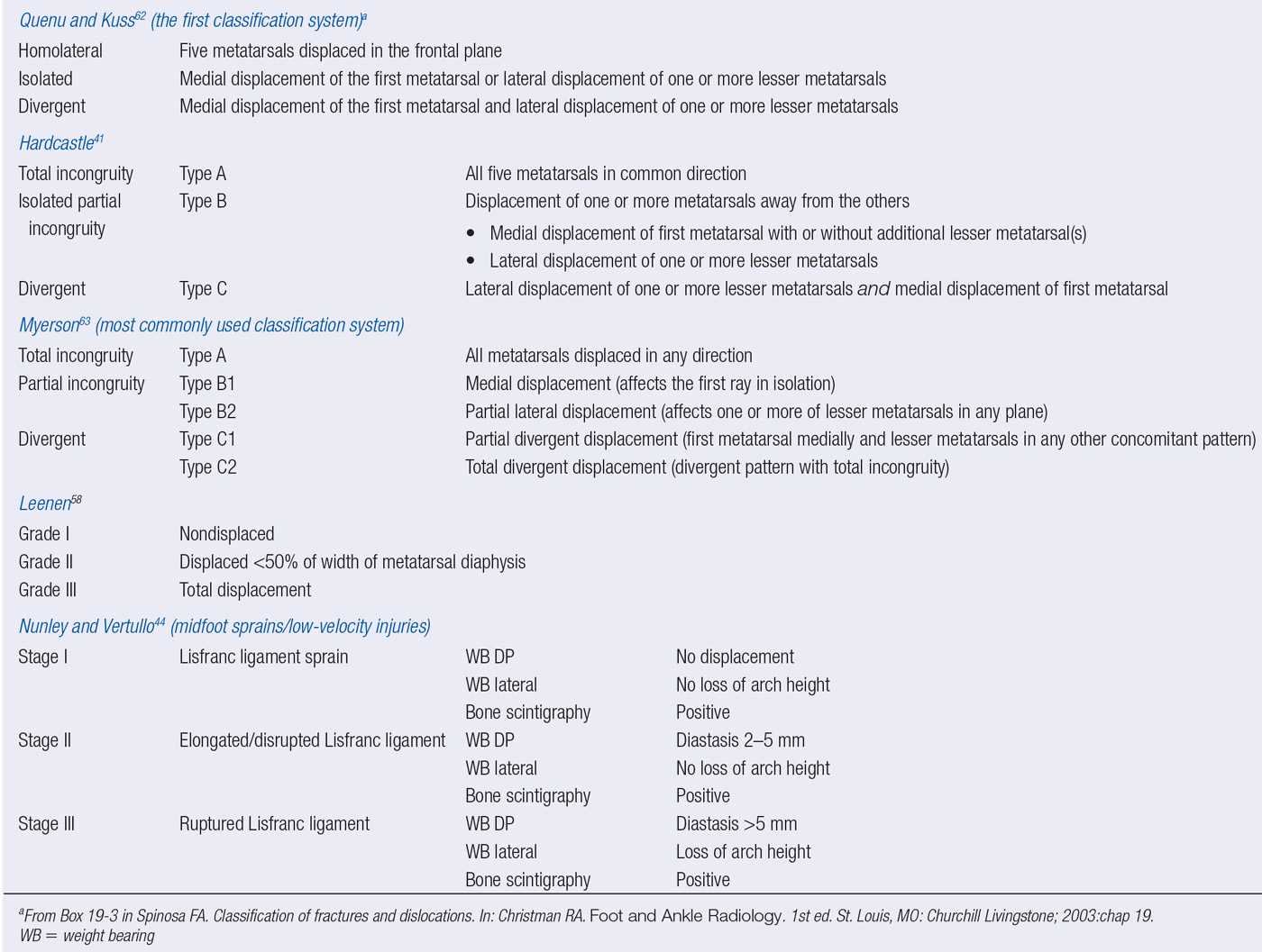
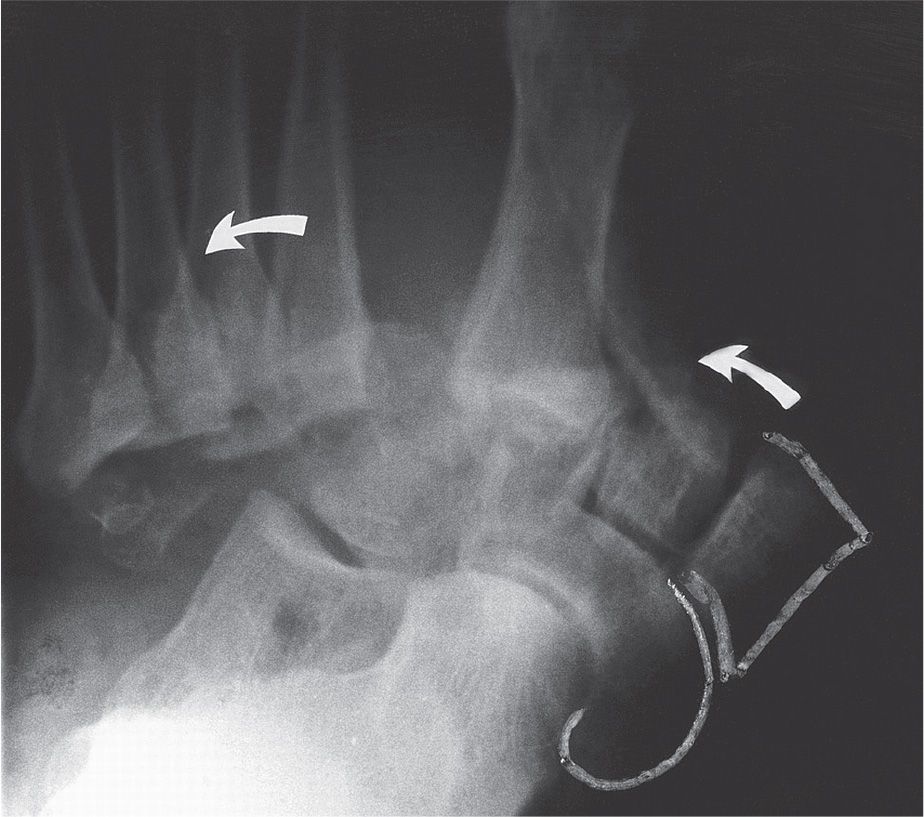
FIGURE 16-17. Divergent Lisfranc fracture–dislocation with lateral cuneiform, navicular, and cuboid fractures (arrows indicate lateral dislocation of the metatarsals). (From Figure 19-11 in Spinosa FA. Classification of fractures and dislocations. In: Christman RA. Foot and Ankle Radiology. 1st ed. St. Louis, MO: Churchill Livingstone; 2003:chap 19.)
CUNEIFORM FRACTURE
Cuneiform fracture is a rare injury, accounting for 4.2% of tarsal fractures, with isolated cuneiform fractures representing 1.7% of tarsal fractures. Most often, cuneiform fracture is associated with tarsometatarsal joint fracture–dislocation and has been observed with midtarsal joint dislocation. The medial cuneiform is the most commonly injured, and dislocation of any cuneiform is rare. This may be due to the confined alignment of the midtarsal bones since, unlike the articulations of the middle and lateral cuneiforms, the medial cuneiform lacks an articulation medially.
| Anatomic Plane for Optimal Visualization of Tarsometatarsal Joint Fracture–Dislocation on Magnetic Resonance Imaging |
Anatomic Structure | Anatomic Plane for Optimal Visualization |
Lisfranc ligament | Oblique axial plane best Can be viewed in axial, sagittal and coronal planes |
Intermetatarsal ligament | Coronal images (almost exclusively) |
Tarsometatarsal ligament | Sagittal images |
Osseous alignment | Sagittal images for dorsal alignment Oblique axial plane for transverse alignment |
Adapted from Foster SC, Foster RR. Lisfranc’s tarsometatarsal fracture-dislocation. Radiology. 1976;120(1):79–83; Preidler KW, Yang Y, Brossom J, et al. Tarsometatarsal joint: anatomic details on MR images. Radiology. 1996;199(3):733–736.
Cuneiform fractures are classified as avulsion fractures, body fractures, or dislocations/subluxations. Avulsion fractures are seen on the medial side of the medial cuneiform, secondary to traction applied by the anterior tibial tendon (Figure 16-21). Body fractures are typically crush injuries from direct force, and dislocations/subluxations are typically associated with Lisfranc fracture–dislocations.
In the case of isolated cuneiform fracture, direct trauma is the most common mechanism of injury. More specifically, direct force accounts for two-thirds of the six reported cases of isolated medial cuneiform fracture, with the remaining cases caused by axial or rotational forces.64 The indirect mechanism is more prevalent in cases causing fractures associated with Lisfranc fracture–dislocations secondary to the forces applied throughout the midfoot. These same mechanisms are implicated in isolated middle and lateral cuneiform fractures.
Clinically, the isolated cuneiform fracture presents with pain and some degree of edema and antalgic gait. Ecchymosis can be present and likely indicates direct trauma. Other findings include pain with transverse plane and frontal plane motion and pain when resisting the tibialis anterior muscle if the medial cuneiform is involved. Dorsoplantar, lateral, and medial oblique radiographs are the initially obtained when this injury is suspected. (Three views are necessary to improve diagnostic accuracy, since only two views lack a tangential appreciation of the midtarsus that reduces the osseous superimposition.) Overlap of the irregularly shaped midtarsal bones is implicated as the cause of 50% of isolated medial cuneiform fractures being misdiagnosed.64,65 CT imaging may be necessary to better understand the fracture pattern in some cases.
The complexity of the midtarsal area, the nondisplaced nature of this fracture, and the presence of subtle fractures in the presence of obvious accompanying fractures impede accurate radiographic evaluation. Availability-based heuristic error also increases the difficulty in diagnosing isolated cuneiform fractures since identifying these rare occurrences is challenging when observed so infrequently.66 Bone scintigraphy, CT, and MRI are other imaging techniques that can be used to improve diagnostic accuracy in equivocal cases. When performing bone scintigraphy, it should be obtained 3 to 5 days after the injury to demonstrate focal uptake; prior to 3 days, a diffuse uptake can present, representing hyperemia or traumatic synovitis.67 CT can make a definitive diagnosis independent of time after injury and is the modality of choice.64,65 CT affords an accurate assessment of the osseous structures, including cortical integrity and small amounts of displacement. However, if a soft tissue injury, stress fracture, or compression injury of the cuneiform is suspected, MRI is more advantageous because of the enhanced soft tissue detail and the ability to detect bone marrow edema and trabecular compression. Both CT and MRI can identify other fractures that must be ruled out since isolated cuneiform fractures should be a diagnosis of exclusion.
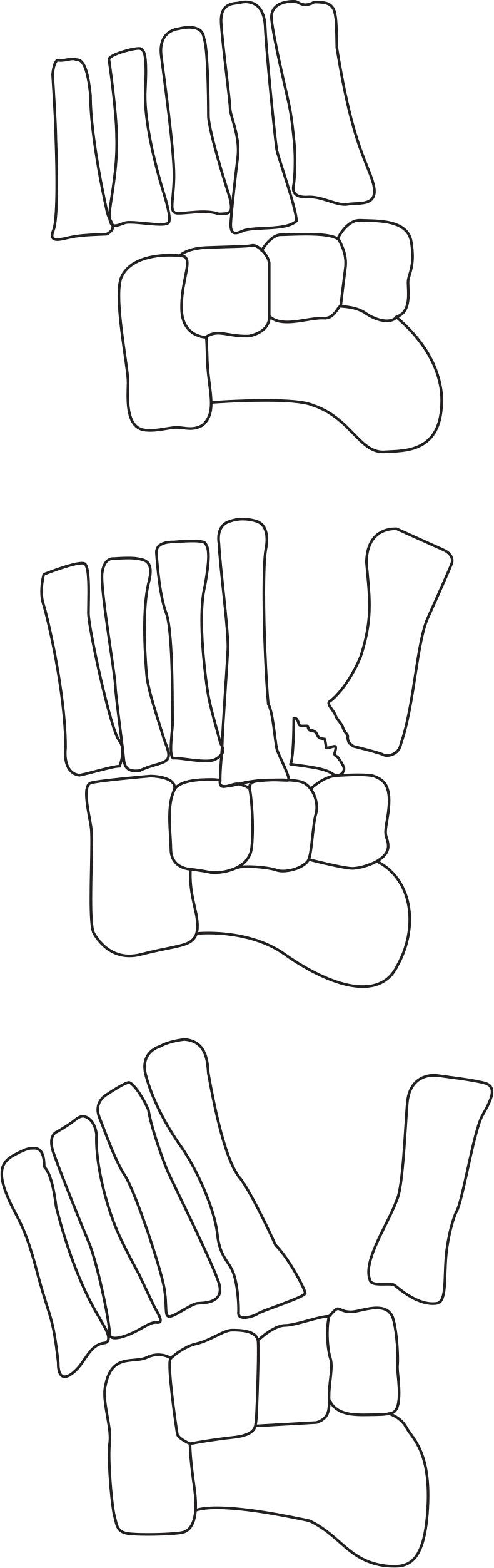
FIGURE 16-18. Schematic representation of Quenu–Kuss Lisfranc fracture–dislocation classification.62 (From Figure 19-9 in Spinosa FA. Classification of fractures and dislocations. In: Christman RA. Foot and Ankle Radiology. 1st ed. St. Louis, MO: Churchill Livingstone; 2003:chap 19.)
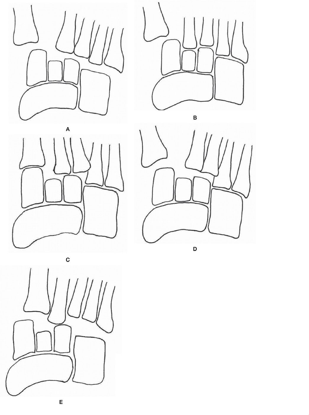
FIGURE 16-19. Schematic representation of Hardcastle classification with Myerson’s modifications.41,63 A: Type A. B: Type B1. C: Type B2. D: Type C1. E: Type C2.
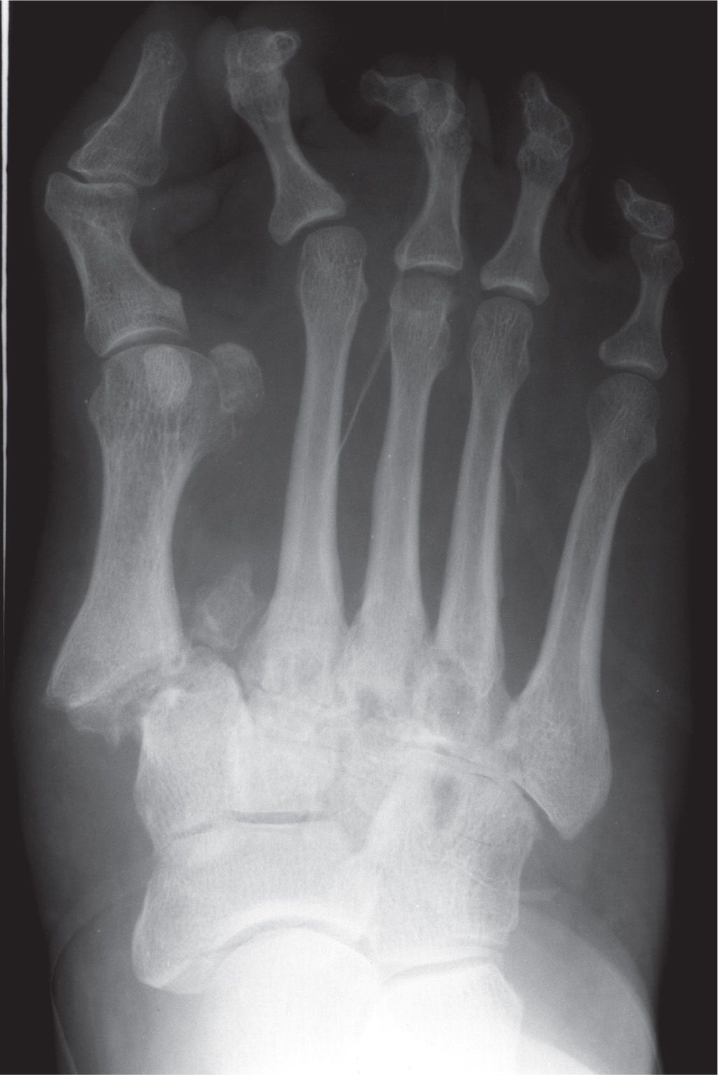
FIGURE 16-20. An example of Hardcastle type B and Myerson type B1.
A bipartite cuneiform can also lead to misdiagnosis. Bipartition is an uncommon developmental variant with an incidence between 0.3% and 2.4%.68 The distinguishing radiographic feature of bipartite medial cuneiform is a horizontally oriented articulation in the sagittal plane (see Figure 6-2 in Chapter 6), which is a rare orientation for a medial cuneiform fracture; fracture is usually observed in the coronal plane. The plantar bipartite cuneiform segment is larger than the dorsal segment, while combined they may be larger than the normal cuneiform size. The first metatarsal articulating surface is also larger than expected when a bipartition is present. Furthermore, the bipartite cuneiform has smooth, well-defined margins. In contrast, a fractured medial cuneiform has an irregular, jagged cleavage between fragments. On MRI, the well-defined space between the bipartite segments, the horizontal lines superior and inferior to the dorsal and plantar segments, and the vertical joint space between the cuneiform segments and first metatarsal base create a unique configuration termed the “E” sign.68 Fractures typically create marrow edema visible on T2-weighted images, while bipartition does not present with marrow edema since the normal biomechanics are not typically altered and a fractured synchondrosis is rare.68
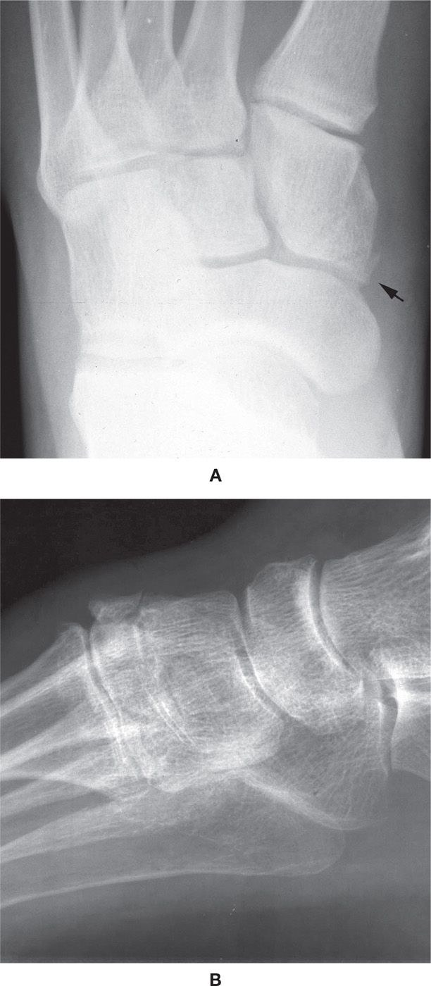
FIGURE 16-21. Medial cuneiform avulsion fractures. A: Posteromedial, with the arrow indicating the fracture fragment along the medial side of the medial cuneiform. B: Anterosuperior.
CUBOID FRACTURE
Cuboid fracture is also a rare injury, accounting for 5% of tarsal fractures.69 Rarely an isolated fracture, this injury frequently occurs with another lateral column fracture or tarsometatarsal joint fracture–dislocation. Cuboid fractures are classified as avulsion fracture, body fracture, fracture–dislocation, or stress fracture.
Avulsion fracture accounts for two-thirds of cuboid fractures. Traction from the plantar calcaneocuboid ligament results most often in the avulsion fragment; some avulsion fractures result from cuboid adduction on the calcaneus, which places excessive tension on the lateral calcaneocuboid ligament. The avulsed fragment is typically observed along the lateral border of the cuboid (Figure 16-22).
Body fractures occur when the foot strikes the ground in a plantarflexed position with rotational motion applied to the forefoot. This indirect force causes a simple crescent shaped, intra-articular fracture fragment. The most common mechanism causing a body fracture is a high-energy abductory force crushing the cuboid between the lateral metatarsals and calcaneus. This nutcracker fracture commonly presents with a navicular fracture.
Since cuboid fracture frequently occurs associated with other fractures, a thorough evaluation of the entire foot is necessary, including radiography; the medial oblique view, in particular, is critical to isolating the cortical margins of the cuboid, best determine the fracture line, and evaluate the anatomic relationship between all of the tarsal bones.69 Accurate assessment of potential displacement is essential; length of the cuboid is critical to reestablishing the length of the lateral column, which significantly impacts the stability and function of the foot.70,71 The significant amount of cancellous bone in the cuboid may limit the visibility of cuboid fracture radiographically. It has been suggested in pediatric cases that repeat radiographs be performed 2 weeks after the injury if a fracture is suspected despite normal initial radiographs; at that time a sclerotic line may become visible.16 CT scanning is best reserved for surgical planning, if necessary; bone scintigraphy is most beneficial when considering a cuboid stress fracture.
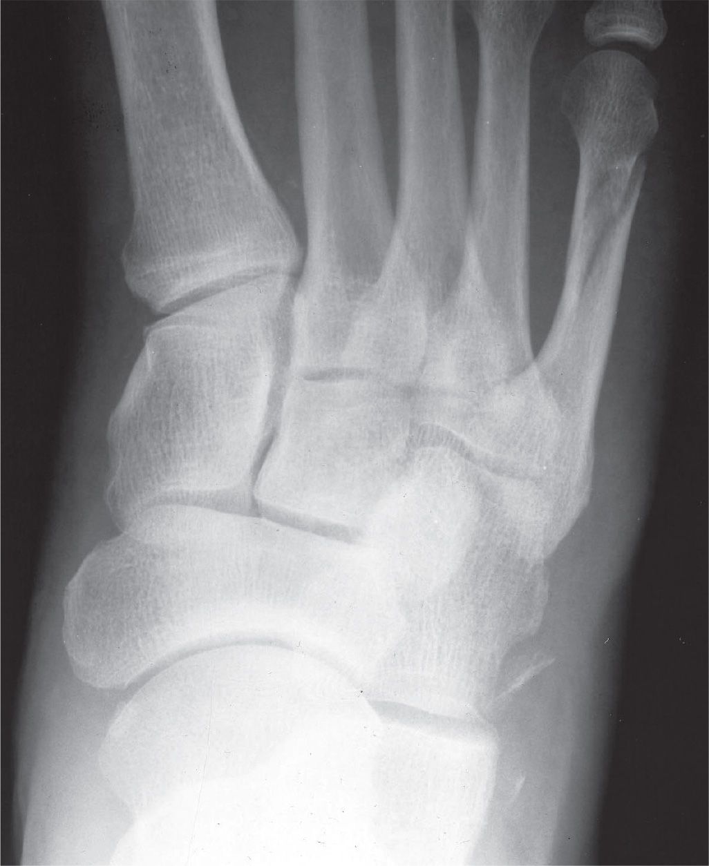
FIGURE 16-22. Lateral cuboid avulsion fracture, including a fifth metatarsal distal diaphyseal spiral fracture.
STRESS FRACTURE
Stress fractures are common fractures in the foot and ankle, possibly accounting for 10% of all sports injuries. The metatarsals are the most common location, accounting for 95% of stress fractures in the foot, and may present bilaterally. In one study of military recruits, 84% of stress fractures were in the metatarsals, calcaneus, and tibia.72 The second metatarsal is involved most often, followed by the third metatarsal. The fourth and fifth metatarsals account for 13% of all metatarsal stress fractures. The fractures are usually diaphyseal; the second most common location is the neck. However, first metatarsal stress fractures are typically located at the base. Despite metatarsal stress fractures involving 80% of injuries in minimalist running, fibular stress fractures are most frequent in athletes.72,73
Stress fractures are classified as fatigue fractures or insufficiency fractures. Fatigue fractures occur when abnormal stress is placed on normal bone. The increased load from muscle activity overwhelms the normal metabolic equilibrium of bone resorption and remodeling, causing the fracture. This is commonly described as an overuse injury and is seen in athletes and military recruits. Insufficiency fractures involve normal stresses applied to bone with deficient structural integrity. This frequently occurs in patients with osteoporosis, or with medications or other illnesses that weaken the osseous structure, such as steroids and rheumatoid arthritis.
Risk factors for stress fractures are related to weight bearing, bone vascularity, training regimen, and the equipment used. Dietary habits, metabolic state, menstrual patterns, anatomic alignment, and overall fitness level also have an influence on the risk of developing stress fractures. In addition to the significant risk when menstrual disturbances are present, females have a relative risk of stress fractures of 0.95 to 3.5 times greater than males.74 This may be secondary to skeletal mass, a lower moment of inertia, and differences in bone density.
The diagnosis is based on clinical symptoms of insidious pain onset over a 2- to 3-week period. Frequently there is also a recent increase in activity level. Tenderness overlying the affected bone is the hallmark sign, and there may be localized edema and increased pain with percussion of the bone involved. Stress fractures of the second and fifth metatarsals, sesamoids, navicular, and anterior tibial diaphysis are high risk for developing nonunions.
Radiography is the most useful imaging test for stress fractures. It is readily available, inexpensive, and can preclude additional tests if findings are present. However, diagnosing stress fractures requires a high level of suspicion, since the fracture may not be apparent on radiographs. Table 16-8 depicts the four basic radiographic patterns of stress fracture.72 Metatarsal stress fractures are typically type I and progress to the type III pattern, which is most commonly seen (Figure 16-7). In comparison to metatarsal stress fractures, calcaneal stress fractures present with a type II pattern with focal sclerosis, likely related to weight-bearing forces (Figure 16-23).
| Patterns of Stress Fractures in the Foot |
Stress Fracture Pattern | Presentation |
Type I | Fracture line demonstrable with no evidence of endosteal bone or periosteal reaction |
Type II | Focal bone sclerosis manifesting as trabecular condensation with cancellous bone and endosteal callus formation |
Type III | Periosteal reaction and external callus |
Type IV | Mixed combination of above patterns |
Adapted from Wilson E, Katz F. Stress fractures: an analysis of 250 consecutive cases. Radiology. 1969;92:481–486.
Radiographic patterns of stress fracture may merely represent the phases of osseous healing. The appearance of a stress fracture is dependent on the time radiographs are obtained following the injury and the type of bone. Radiographic findings lag behind clinical symptoms by 2 to 3 weeks; some stress fractures may never become evident. Wilson and Katz72 noted that initial radiographs of 250 military recruits were negative in 24% of calcaneal stress fractures and in 17% of all cases.
The earliest finding of a cortical bone stress fracture, such as in the metatarsal, may be a subtle radiolucency or cortical break secondary to resorption; a compensatory periosteal reaction often follows (Figure 16-7). The late findings include thickening and sclerosis of endosteal and periosteal bone, weeks to months after the onset of symptoms. In contrast, cancellous bone stress fracture demonstrates a focal sclerotic band perpendicular to the trabeculae.75 At times, this sclerotic line is not visible for up to 24 weeks after the injury.66
If a stress fracture is suspected despite nondiagnostic radiographs, the study should be repeated 2 to 3 weeks later. However, if there is urgency to determine the presence of a stress fracture, bone scintigraphy or MRI can be performed.75 Bone scintigraphy is particularly useful for early detection since it has a sensitivity of nearly 100%, which is more than twofold greater than radiographs. In fact, findings have been observed on technetium bone scans prior to clinical evidence of the fracture.74,76 Stress fractures were identified on initial radiographs in 42% of cases while on bone scintigraphy in 95.8% of cases.77 However, the specificity of bone scintigraphy is significantly lower than radiography for localization and characterization of fracture lines. There is also potential confusion with other pathology that exhibits increased focal uptake, such as bone tumor and osteomyelitis.66,74 When a stress fracture is observed, there is a sharply marginated or fusiform area of increased uptake, involving one cortex or the entire width of the bone. Increased uptake is present in all three phases of the study.78 In contrast to stress fractures, stress reaction has a positive focal uptake during the first two (blood and delayed pool) phases only.

FIGURE 16-23. Stress fracture, calcaneus (type II: ill-defined increased density in cancellous bone, arrows).
Ultrasonography is sensitive for occult fracture of more superficial bones, such as the metatarsals. A hypoechoic band, cortical step-off, and periosteal reaction can be indicative of a fracture. A hyperechoic area can be indicative of bone callus formation consistent with remodeling during fracture healing.
MRI can be cost prohibitive but is becoming the preferred diagnostic imaging modality for stress fracture. Its sensitivity is at least as high as bone scintigraphy and specificity is much higher. The greatest visualization of MRI findings occurs when the study is performed within 3 weeks of symptoms onset. MRI is highly sensitive for endosteal marrow edema and periosteal edema, which are the earliest findings of stress fractures. These findings are observed as increased signal intensity on fluid filled sequences and decreased signal intensity on T1-weighted images.74,75,79 Muscle edema, cortical thickening, and hypointense fracture lines affecting the cortical or cancellous bone may also be evident.
CT imaging has also been used for evaluating stress fractures. It can be useful for distinguishing between stress fracture and stress reaction; however, MRI remains more sensitive and specific in this scenario. Unlike CT, MRI does not expose the patient to ionizing radiation, so it is now more commonly used for diagnosing stress fractures when faced with equivocal radiographs.
However, CT is considered the gold standard for evaluating navicular stress fracture. In this case, CT assists with understanding fracture characteristics, comminution, displacement, and healing.6,80,81 CT has proved to be more accurate in the detection of navicular stress fracture than MRI. However, all stress reactions were identified using MRI while none were observed on CT images.82 A classification based on CT appearance was developed to guide treatment and forecast healing time since nonsurgical versus surgical treatment remains controversial. This classification relies on the location of the fracture line and by the presence of risk factors associated with poorer prognoses (Table 16-9).83 It is important to keep in mind that this classification has not been validated and others have noted flaws in the conclusions regarding the treatment recommendations.84
The navicular stress fracture is located within the zone of maximum shear stress, which is in the central one-third of the body just lateral to the center of the talar articular surface. The fracture line is linear in the sagittal plane or slightly oblique from dorsal–medial to plantar–lateral (Figure 16-24). Radiographically, the fracture appears as a sclerotic line along the proximal articular border in the dorsoplantar view; however, its visualization may be difficult.75 A review of 55 cases revealed that 11% of navicular stress fractures were accurately diagnosed using CT after being missed on radiographs initially.85 The fracture is typically incomplete, thus contained within the dorsal 5 mm of the navicular.66,81 CT in the anatomic anteroposterior plane with the foot supinated and forefoot elevated will provide the best opportunity for identifying the fracture.66
| Computed Tomography–Based Classification of Navicular Stress Fractures |
Type | Description | Treatment |
I | Dorsal cortical fracture | Conservative or ORIF in an athlete |
II | Dorsal fracture propagates into navicular body | Conservative or ORIF in active/athletic patient |
III | Fracture penetrates second cortex (plantar, medial, or lateral) | Most often ORIF |
Modifiera | Description | Notes |
A | Avascular necrosis | Most often seen in type III |
C | Cystic degeneration | Most often seen in type I |
S | Sclerosis of fracture lines | Most often seen in type II |
aA modifier can be assigned to any type within the classification.
Calcaneal stress fracture is easily overlooked secondary to the cancellous nature of the bone. When present, a dense, sclerotic band is observed in the posterior calcaneal body. This is a common injury with initial weight bearing after periods of immobilization.
Tibial stress fractures are located along the anterior aspect of the diaphysis. Radiographically, in the lateral view, the anterior cortex appears thickened and contains a lucent line running through it.
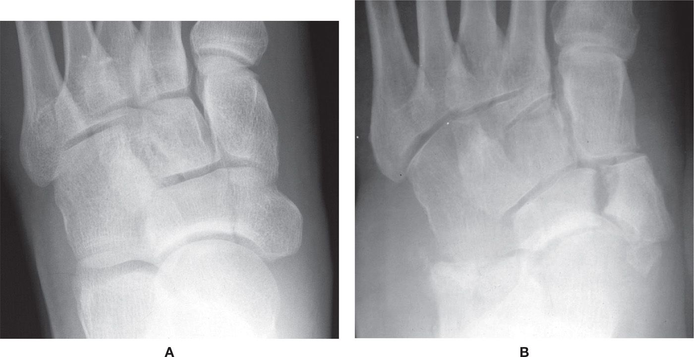
FIGURE 16-24. Stress fracture, navicular. A: Nondisplaced. B: Displaced, with an accessory navicular.
NAVICULAR FRACTURE
Navicular fractures are rare, making up 0.3% of fractures in one study.72 Several classifications have been published to describe navicular fractures.86–88 Eichenholtz provided a more simplistic classification, which identifies the cortical avulsion fracture, tuberosity fracture, and body fracture as the three main fracture types. Stress fracture of the navicular, which was previously discussed, was later identified as a fourth type of navicular fracture.89 Navicular fractures most commonly occur in patients between 30 and 60 years of age and are two times more prevalent in females than in males. Patients who suffer navicular fractures often have other associated foot fractures 47% to 50% of the time.90–92
Cortical avulsion fracture accounts for 47% of navicular fractures in the Eichenholtz classification (Figure 16-25).91 This injury usually results from an inversion twist or sprain with the foot in plantarflexion. Dorsal lip fractures result from dorsal capsule or dorsal talonavicular ligament avulsion. These fractures are best seen on the lateral foot radiograph.
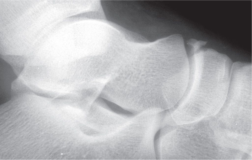
FIGURE 16-25. Dorsal avulsion fracture of navicular.
Navicular tuberosity fracture occurs 24% of the time (Figure 16-26).91 This injury results from MVA, fall, sprain, and twisting injury.92 The mechanism of injury involves forced eversion of the foot, resulting in avulsion of the tuberosity.89,91,93,94 However, there is some controversy as to which anatomic structure actually causes the avulsion fracture. Some authors believe the culprit to be the posterior tibial tendon, while others believe it to be the spring ligament.89,91,93 Anterior calcaneal process fractures have been observed in 50% of patients with navicular tuberosity avulsion fracture.90,92 Dorsoplantar and lateral radiographic views are commonly used to diagnose this fracture; the lateral oblique view might provide additional information.94 The diagnosis becomes more challenging when radiographs reveal an accessory navicular; furthermore, the accessory navicular itself could fracture or become avulsed.91,93,94 Contralateral films might be helpful, but 50% to 89% of patients with an accessory navicular have a bilateral presentation.95–97 Table 16-10 delineates the three types of accessory navicular (see Figures 6-58 and 6-59 in Chapter 6).
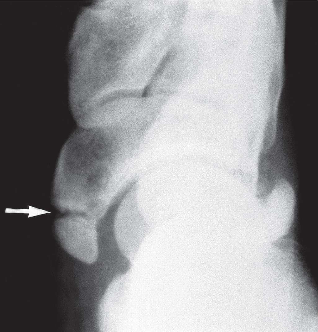
FIGURE 16-26. Avulsion fracture of the navicular tuberosity (arrow). (From Figure 19-12 in Spinosa FA. Classification of fractures and dislocations. In: Christman RA. Foot and Ankle Radiology. 1st ed. St. Louis, MO: Churchill Livingstone; 2003:chap 19.)
| The Three Types of Accessory Navicular |
Accessory Navicular Type | Description |
1 | Sesamoid bone within the posterior tibialis tendon |
2 | Arises from secondary center of ossification, connected to main body of navicular via fibrocartilaginous bridge or hyaline cartilage |
3 | Arises from secondary center of ossification with bony bridge to main body of navicular |
Related posts:

Stay updated, free articles. Join our Telegram channel

Full access? Get Clinical Tree


