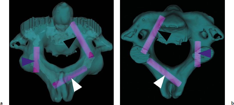
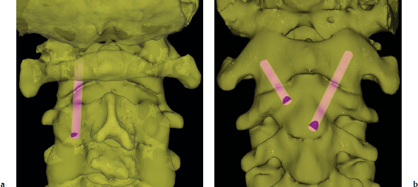
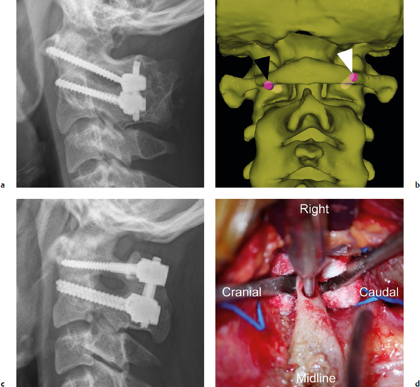
11 A variety of techniques have been described for upper cervical fixation. Although advances in technology for screw fixation have enabled superior fixation methods over traditional wiring techniques, the application of screw fixation in the upper cervical spine entails its own set of challenges and pitfalls. Ultimately, the method utilized by surgeons depends on their comfort and familiarity with the approach and the patient’s anatomy and underlying pathology. This chapter summarizes the techniques for achieving screw fixation in the upper cervical spine, and discusses the prevention of complications associated with these fixation techniques. C1–C2 transarticular fixation can be achieved via an anterior or posterior approach. Much like any technique for instrumentation of C1 and C2, extensive preoperative imaging, including plain radiographs, magnetic resonance imaging (MRI), and computed tomography (CT), is essential for operative planning. Sagittal and parasagittal reformatted images are critical for determining the feasibility of this technique with regard to the location of the vertebral arteries. Sometimes the C2 pars may be too thin or the position of the vertebral artery too medial or dorsal to permit posterior transarticular screw placement. It is estimated that up to 20% of cases exhibit anatomic limitations for using the transarticular screw, so in no way are these anatomic variations a rarity.1,2 The starting point of the posterior transarticular C1–C2 screw is ~ 3 mm proximal to the C2–3 facet joint line and 3 mm lateral to the medial border of the lateral mass (Fig. 11.1a). The optimal trajectory in the coronal plane is to aim 0 to 5 degrees medially. The amount of medial angulation depends on the location and course of the vertebral artery at the level of the C2 pars. If there is a subluxation of C1 on C2, using any part of the C1 anterior tubercle to determine the trajectory in the sagittal plane is not recommended because the position of the C1 anterior tubercle is determined by the degree of subluxation. Instead, the screw trajectory needs to be directed as dorsally as possible to minimize the possibility of violating the anteroinferiorly located vertebral artery groove of C2.2,3 Whenever possible, we believe that it is much better to place the screw only after reducing the C1–C2 joint first. This can be done sometimes by retracting (translating the neck posteriorly) and extending the neck. Too much extension, however, can make the screw trajectory impossible, so this should be checked prior to the prep and drape under fluoroscopy. Intraoperatively, one can place a cable under the arch of C1 and caudal to the spinous process of C2, underneath the still attached semispinalis cervicis. By tensioning the cable, the C1 ring is pulled posteriorly. If the patient has severe cord compression at the C1 level, it is sometimes possible to pull the arch posteriorly first with a Kocher hemostat or tenaculum, so as to create more space for the cord, prior to placing the cable. If this is not possible, then one should not attempt to place a cable underneath the arch of C1, as it can cause cord injury. After the C1–C2 joint is reduced, the screw tip should be directed toward the bottom half of the anterior tubercle of C1 under fluoroscopy. It should stop short of the posterior cortex of the tubercle, because a longer screw will protrude into the soft tissues, placing the internal carotid artery at risk. The risk of vertebral artery injury with this technique is estimated to be 4.1%.4 If the artery is injured, a short screw should be placed to tamponade the bleeding. With a minor injury, the artery may be able to repair itself with time. Postoperatively, angiographic studies can be obtained to assess the injury. Most importantly, placement of a screw on the contralateral side should not be attempted, because bilateral vertebral artery injury can result in severe neurologic deficit or death. Biomechanical studies of posterior transarticular screws have shown excellent stability except in flexion and extension. The posterior wiring between C1 and C2 can usually address this problem. The anterior transarticular technique is another method for providing rigid C1–C2 fixation. Lu et al5 described the anatomic parameters for anterior C1–C2 transarticular screw fixation (Fig. 11.1b). They concluded that with a starting point at the concavity on the anterior cortex of the C2 arch, the screw trajectory should be angled 20 degrees laterally and 20 degrees posteriorly to be placed safely. With this method, a screw length of 15 to 20 mm is usually sufficient.5 More recently, percutaneous methods for anterior transarticular screw placement have also been described.6,7 This technique uses a starting point at the anterior inferior end plate of the C2 vertebral body with a trajectory that is aimed 20 to 30 degrees laterally and 20 to 28 degrees posteriorly. Because of the more caudal starting point, a longer screw length of 40 to 50 mm can be achieved. Before an anterior approach for C1–C2 transarticular fixation is utilized, several challenges to placing anterior transarticular screws should be considered. These include the potential damage to the superior laryngeal nerve as well as problems with dysphagia that are associated with an anterior procedure. Additionally, the mandible may make it difficult with even open anterior approaches to adequately decorticate and bone graft the C1–C2 joints bilaterally, necessitating transoral decortication and grafting. Lastly, the trajectories of the anterior screws are directed from medial to lateral. This means that while the contralateral screw might be easier to place, screw placement for the ipsilateral side of the approach requires extensive retraction of the midline structures past the midline.8 Nonetheless, this approach is a useful adjunct to a cervical spine surgeons’ armamentarium because certain circumstances make this a better option for fixation (i.e., abnormal vertebral artery course or the absence of posterior osseous structures due to prior surgery). The technique for utilizing C1–C2 segmental fixation was first described by Goel and Laheri9 in 1994 with the use of screws and plates, and then by Harms and Melcher10 in 2001 with the use of screws and rods. We prefer to use traction placed at 15 to 18 lb through Gardner-Wells tongs, although a Mayfield headholder may be used. The techniques for instrumenting C1 and C2 segmental screws are discussed in the following subsections. The inferior border of the posterior surface of the C1 posterior arch may be delineated with electrocautery. However, care must be taken with the superior border in the lateral portion, because injury to the vertebral artery can occur. A Penfield No. 4 or No. 2 dissector is used to subperiosteally dissect the C2 ganglion and venous plexus off of the arch. Keeping the dissection completely subperiosteal is the key to avoiding unnecessary bleeding from the venous sinuses. The C2 nerve root and its dorsal root ganglion, which supplies the greater occipital nerve, is between the C1 posterior arch and C2 pars and posterior to the C1–C2 facet joint, and care is taken to gently retract the nerve distally toward the C2 lamina using a Penfield dissector. A large venous plexus lies just cranial, lateral, and deep to the C2 nerve root, and care should be taken not to manipulate this area too much unless a decision is made to sacrifice the C2 nerve root, in which case aggressive bipolar cautery can be used to cauterize the venous plexus. We usually preserve the C2 nerve root and therefore use thrombin-based hemostatic agents, Surgicel, and mechanical pressure by way of a cottonoids to control the bleeding. Again, keeping the dissection plane strictly sub periosteal is a key to minimizing bleeding. Although some have recommended routinely sacrificing the C2 nerve,9,11 a recent study found that doing so can result in disabling pain in some patients.12 Prior to instrumentation of the C1 lateral mass (Fig. 11.2a), the C1–C2 articulation is decorticated with the use of a bur while the C2 nerve root is retracted cranially and fresh frozen allograft or autograft bone is placed along with the bone dust from the decorticated joint. When decorticating, be aware of how close the artery is to the subchondral bone at C2 by examining the CT scan. Screw placement can now commence. We first use a Penfield No. 4 dissector to identify the medial and lateral borders of the C1 lateral mass. Midway between the medial and lateral borders is the starting point for our screw (Fig. 11.2b). We then notch the inferior aspect of the C1 posterior arch with a bur to create a space into which the screw will be recessed.13 This recess enables a more caudally directed screw trajectory because the overhang of the C1 posterior arch is eliminated. Another advantage of the notch recess is that the tulip of the screw head can also sit more cranially when the screw is inserted so that the screw heads are not too crowded after placement. Nevertheless, this step is performed if and only if the corresponding sagittal cuts on the CT scan as well as the MRI show that the vertebral artery would not be compromised with such a maneuver. If there is a risk of vertebral artery injury, we usually dissect the artery off of the cranial aspect of C1 and protect it with a cottonoid prior to forming the recess.13 Fig. 11.2a–d C1 screws. (a) A radiograph shows C1 lateral mass screws and C2 pedicle screws. (b) Trajectories of a C1 lateral mass screw (black arrowhead) and a C1 posterior arch screw (white arrowhead). (c) A radiograph shows C1 posterior arch screws and C2 pedicle screws. (d) A pilot hole is made using a bur for a right posterior arch screw. The Penfield retractor then moves distally to protect the C2 nerve root. A cottonoid can be used to cushion the nerve root so that direct pressure from the Penfield is not applied to the nerve root. A bur is then placed into the recess that was created until a bony end point is reached. A pilot hole is created using the bur and deepened and enlarged using a batterypowered drill. We aim the C1 lateral mass screw 0 to 10 degrees medially.13,14 The screw length used is usually between 26 and 32 mm. Occasionally, the anatomy might lend itself to longer screw lengths, but care must be taken to avoid violation of the anterior cortex by more than one or two screw threads due to the risk of injury to the internal carotid artery anteriorly.15 Whenever possible, we utilize a C1 posterior arch screw (Fig. 11.2c), which requires less of a soft tissue dissection than a lateral mass screw under C1 posterior arch, with lower probability of postoperative occipital neuralgia.12,16 In addition, the screw has purchase in more bone with this technique. After dissecting under the posterior arch (similar to the method for C1 lateral mass screw placement), the vertebral artery is subperiosteally dissected cranially away from the C1 posterior arch protected using cottonoids and a Penfield or a Freer elevator (Fig. 11.2d). Next, a pilot hole is created using a bur and enlarged and deepened with a battery-powered drill, followed by tapping and screw insertion. The starting point is at the posterior cortex of the posterior arch over the medial-lateral midpoint of the lateral mass and at the cranialcaudal midpoint of the posterior arch or 1 or 2 mm cranial to it, depending on the shape of the posterior arch. The optimal trajectory is 0 to 10 degrees of medial angulation and the sagittal trajectory should aim for the inferior 20% of the anterior arch of C1 on the lateral radiography or fluoroscopy to avoid occipital–C1 joint violation. As an anatomic landmark for the starting point of the C2 pedicle screw, we define the medial border of the pedicle by following the superior border of the C2 lamina anteriorly. This ventral lamina becomes the medial wall of the pedicle and defines our medial trajectory for the pedicle screw. The starting point is 5 mm lateral to the intersection of the lamina and medial wall of the pedicle (Fig. 11.3a). We aim 20 to 25 degrees medially and 20 to 25 degrees cranially to achieve the optimal trajectory for the pedicle screw. Generally, it is better to err medially than laterally, because medially the space available for the cord permits small medial breaches without clinical consequence. In addition, because the medial cortical wall of the pedicle is very thick, it is much less vulnerable to violation. A lateral and caudal breach, however, can result in vertebral artery injury (Fig. 11.3b). Therefore, we try to place the trajectory as medial and cranial as possible. We notch the starting point with a bur and then switch to a cervical pedicle probe. If we encounter resistance, we use a drill with a drill stop that we sequentially lengthen, so as to prevent plunging, under hand power. We then use a balltipped probe to palpate for any breaches, and tap and then palpate again prior to placing the screw.
Upper Cervical Screw Fixation Techniques: How to Avoid Complications
 Introduction
 Screw Fixation Techniques
Transarticular Screw
Posterior Transarticular Screw
Anterior Transarticular Screw
C1–C2 Segmental Screw Fixation
C1 Lateral Mass Screw
C1 Posterior Arch Screw
C2 Pedicle Screw
Related posts:
 Cervical Disk Arthroplasty
Anterior Cervical Decompression and Fusion Techniques: Anterior Cervical Decompression and Fusion, Corpectomy, and Foraminotomy
Indications and Techniques of Cervical Pedicle Screws C3-7 for Degenerative Conditions
Cervical Sagittal Balance: What Is Normal and What Is the Effect on Reconstruction Outcomes
Complications of Anterior Surgery: Vertebral Artery Injury, Esophageal Perforation, and Dysphagia
Navigation for Cervical Reconstruction Surgery
Cervical Disk Arthroplasty
Anterior Cervical Decompression and Fusion Techniques: Anterior Cervical Decompression and Fusion, Corpectomy, and Foraminotomy
Indications and Techniques of Cervical Pedicle Screws C3-7 for Degenerative Conditions
Cervical Sagittal Balance: What Is Normal and What Is the Effect on Reconstruction Outcomes
Complications of Anterior Surgery: Vertebral Artery Injury, Esophageal Perforation, and Dysphagia
Navigation for Cervical Reconstruction Surgery
![]()
Stay updated, free articles. Join our Telegram channel

Full access? Get Clinical Tree


