The Temporomandibular Joint
Thomas H. Berquist
INTRODUCTION
Disorders of the temporomandibular joint (TMJ) are reported in up to 28% of the population in the United States.1,2,3 Temporomandibular internal derangement most commonly occurs in women between 20 and 40 years of age.1,2 Imaging plays an important role in the diagnosis of TMJ disorders since accuracy of the clinical examination may be as low as 54%.4
Magnetic resonance imaging (MRI) has replaced arthrography and computed tomography (CT) as the imaging modality of choice for evaluating internal derangement of the TMJ.3,5,6,7,8 MR can directly visualize the disc, accurately determine the disc position, and evaluate condylar motion in a noninvasive manner.3,9,10,11,12,13 MR studies also provide information on the state of hydration and morphology of the disc that may be helpful in staging internal derangement.14,15,16,17 Although it will not rival the resolution of CT in examining bony detail, MRI provides an accurate picture of most bony abnormalities.18,19,20 In addition, MRI demonstrates other intra-articular and periarticular abnormalities.3,21,22
Ultrasound has been evaluated as a screening technique in recent years. However, this technique requires considerable experience by the examiner.23 To date, sonography is not frequently utilized to evaluate internal derangement of the TMJ.
ANATOMY
The TMJ is a synovial joint divided into superior and inferior compartments by a fibrous disc.24,25 The two compartments do not communicate unless there is a perforation of the disc. The joint is formed by the mandibular condyle and articular fossa of the temporal bone (Fig. 4.1).24,25,26,27,28
The mandibular condyle is between 15 to 20 mm when measured from left to right and 8 to 10 mm in anteroposterior dimension. Axial images of the condyle demonstrate that the angle formed by the two condyles is about 145° to 160°28 (Fig. 4.2). Thus, one has the option to obtain oblique sagittal images in the plane of both condyles while obtaining sagittal images. Articular anatomy varies with age and gender as degenerative changes do occur with aging.26,28
The disc is normally biconcave with three distinct segments (Fig. 4.3). The thickest portion of the disc is the posterior band. The posterior band is separated from the anterior band by a thin, intermediate zone, thus the concave or “bow-tie” appearance.24,25,27 Disc stability is provided by multiple attachments. Posteriorly, a ligament, also referred to as the bilaminar zone, serves to attach the disc and capsule to the condylar margin and temporal bone.24,25 The posterior attachment contains a rich vascular supply and neural elements that innervate the disc.25,27,28,29
The disc attaches to the superior belly of the lateral pterygoid muscle anteriorly (Fig. 4.1).21,22,24,28 The muscle tension is balanced by the elastic fibers in the bilaminar zone.24,25,29 The pterygoid muscles course medially to insert on the pterygoid plates. Therefore, anteriorly displaced discs tend to lay somewhat anteromedially. There are also additional anterior, medial, and lateral capsular attachments.25
When the mouth is in the closed position, the posterior band (Fig. 4.3) is normally at the apex of the mandibular condyle.24,25,30 The inferior concave portion of the disc rests on the curved surface of the mandibular condyle. With opening of the mouth, the condyle moves forward and the normal disc remains centered over the condyle.24,30 In the fully open position, the thin intermediate zone rests between the condyle and articular eminence of the temporal bone (Fig. 4.3).25 During normal motion in the sagittal plane, the disc moves in a convex path over a distance of 10 mm.31,32
IMAGING TECHNIQUES
Many different imaging protocols have been proposed for evaluating the TMJ with 1.5 and 3.0 T systems.3,18,33,34,35,36,37,38,39,40 Most rely upon sagittal images in the closed and open
positions, though coronal images, motion studies, and intravenous or intra-articular gadolinium studies have also been advocated.41,42,43 Ideally, examinations should be tailored on the basis of clinical findings and the philosophy of the referring physician or dentist.44,45,46
positions, though coronal images, motion studies, and intravenous or intra-articular gadolinium studies have also been advocated.41,42,43 Ideally, examinations should be tailored on the basis of clinical findings and the philosophy of the referring physician or dentist.44,45,46
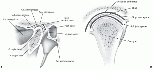 Figure 4.1 Illustration of the temporomandibular joint in the sagittal (A) and coronal (B) planes. |
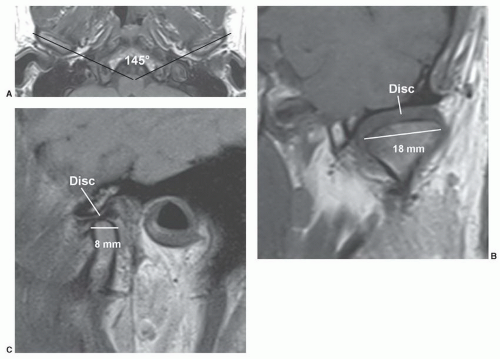 Figure 4.2 A: Axial MR image of the mandibular condyles demonstrating an angle of 145° on the axial image. B: Coronal image of the mandibular condyle measuring 18 mm in transverse width. C: Sagittal MR image demonstrating the mandibular condyle measuring 8 mm in anteroposterior dimension. |
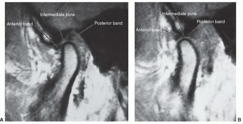 Figure 4.3 Sagittal T1-weighted MR images in the closed (A) and open (B) positions. The posterior band is normally above the condyle in the closed position (A). In the open-mouth position (B), the disc is more easily appreciated. The thin intermediate zone rests between the condyle and eminence of the temporal bone. |
 Figure 4.4 Sagittal (A) and coronal (B) MR images demonstrating the articular anatomy of the cranial aspect of the temporomandibular joint. |
Certain basic parameters are necessary for examination efficiency and optimal image quality at all field strengths. A small (3 to 5 in) multichannel surface coil is mandatory to provide sufficient signal-to-noise to assure high image quality. Bilateral coupled coils (Fig. 4.5A and C) are most
commonly used. This permits both TMJs to be studied in the same time required for unilateral examinations.3,34,37,38,39 Newer scanners allow the dual coils to be used with the head coil, which adds versatility to the examination (Fig. 4.5D). A small field of view (FOV) (10 to 14 cm), 256 × 256 or 256 × 192 matrix, and 1 to 3 excitations are most often used.37,40,42,47,48 However, some authors prefer 512 × 512 matrix when using gradient-echo sequences.48
commonly used. This permits both TMJs to be studied in the same time required for unilateral examinations.3,34,37,38,39 Newer scanners allow the dual coils to be used with the head coil, which adds versatility to the examination (Fig. 4.5D). A small field of view (FOV) (10 to 14 cm), 256 × 256 or 256 × 192 matrix, and 1 to 3 excitations are most often used.37,40,42,47,48 However, some authors prefer 512 × 512 matrix when using gradient-echo sequences.48
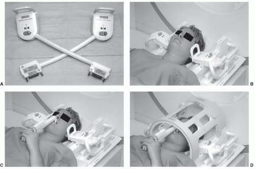 Figure 4.5 Coils and opening device for TMJ imaging. A: Dual loop array coils. B: Patient positioned with dual coils for bilateral TMJ imaging. C: Patient positioned with dual coils and opening device used for cine imaging. D: Patient positioned with dual TMJ coils and head coil in place. Opening device can be used for cine images. |
IMAGE PLANES AND PULSE SEQUENCES
Two localizer (axial and coronal) scout images are obtained (SE 17/794, FOV 16 cm, 256 × 256 matrix), using 3-mm sections at 3.3-mm splits through palpated TMJ region, one excitation, scan to select image planes for sagittal and coronal images (Fig. 4.6) (Table 4.1). The condyles are oriented about 30° medially on the axial view. Although controversial, most institutions orient the image planes obliquely for sagittal and coronal studies (Fig. 4.6). Whether one selects direct or oblique sagittal images, most institutions use 2- to 4-mm-thick sections at 1.5 and 3.0 Tesla field strengths.3,37,39,47,49,50
Several approaches have been suggested for sagittal imaging at 1.5 and 3.0 Tesla (Table 4.1). Basic anatomy and disc position can be evaluated using T-1 weighted or, more recently, turbo spin-echo proton density sequences in the open and closed positions.3,37,38,39,51,52,53,54,55 Parameters with turbo spin-echo proton density weighted images include TE 23, TR 2,000, 256 × 256 or 256 × 192 matrix, 2- to 3-mm-thick sections, one excitation, and an FOV of 12 to 14 cm.No attempt is made to obtain a full open-mouth image unless specifically requested by the clinician. In the closed-mouth images, the condyle is seated in the glenoid fossa with the disc interposed between the condylar head and the glenoid (Fig. 4.7). Because the disc is predominantly low in signal and is tightly placed between two low signal areas of cortex, it can be difficult to visualize adequately in many instances. If the patient assumes a partial open-mouth position, the condylar head moves slightly out of the glenoid fossa, allowing the disc to be separated from the bony surfaces so that it is more easily seen in its entirety (Fig. 4.2B).
In the partial open-mouth position, the disc is often in a normal position, having reduced from an anteriorly displaced position. Hence, many false-negative studies could
result if the partial open-mouth images are relied on for diagnosing disc position. It is important to judge the disc position on the closed-mouth images and rely on the partial open-mouth images to note the size, shape, and signal characteristics (Figs. 4.2 and 4.7). The information obtained on the partial open-mouth images concerning the disc size and shape can then be applied to the closed-mouth images to locate the disc position more confidently (Figs. 4.2 and 4.7). If the closed-mouth images alone are used, a small but significant number of cases will be almost nondiagnostic.3,36
result if the partial open-mouth images are relied on for diagnosing disc position. It is important to judge the disc position on the closed-mouth images and rely on the partial open-mouth images to note the size, shape, and signal characteristics (Figs. 4.2 and 4.7). The information obtained on the partial open-mouth images concerning the disc size and shape can then be applied to the closed-mouth images to locate the disc position more confidently (Figs. 4.2 and 4.7). If the closed-mouth images alone are used, a small but significant number of cases will be almost nondiagnostic.3,36
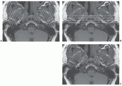 Figure 4.6 Scout images for oblique sagittal (A), conventional coronal (B), and oblique coronal (C) image planes. |
Table 4.1 Image Parameters for the Temporomandibular Joint | ||||||||||||||||||||||||||||||||||||||||||||||||
|---|---|---|---|---|---|---|---|---|---|---|---|---|---|---|---|---|---|---|---|---|---|---|---|---|---|---|---|---|---|---|---|---|---|---|---|---|---|---|---|---|---|---|---|---|---|---|---|---|
| ||||||||||||||||||||||||||||||||||||||||||||||||
Other approaches to sagittal imaging have also become popular in recent years. T2-weighted spin-echo, fat-suppressed fast spin-echo, or turbo spin-echo sequences in the open and closed positions have proved useful for
identifying joint effusions.15,45,46,53,54,55,56 Fast or turbo spin-echo T2-weighted sequences have largely replaced conventional spin-echo sequences to reduce scan time47,52 (Table 4.1). Proton density sequences (Fig. 4.7) (Table 4.1) are useful in evaluating disc morphology in a similar fashion to meniscal pathology in the knee (see Chapter 7). Gradient-echo sequences have also been used in both closed and open positions or with multiple small increments to produce a cine-loop motion study.57
identifying joint effusions.15,45,46,53,54,55,56 Fast or turbo spin-echo T2-weighted sequences have largely replaced conventional spin-echo sequences to reduce scan time47,52 (Table 4.1). Proton density sequences (Fig. 4.7) (Table 4.1) are useful in evaluating disc morphology in a similar fashion to meniscal pathology in the knee (see Chapter 7). Gradient-echo sequences have also been used in both closed and open positions or with multiple small increments to produce a cine-loop motion study.57
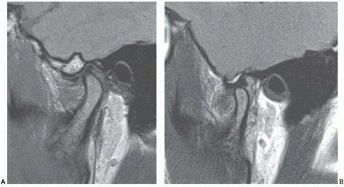 Figure 4.7 Turbo spin-echo proton density sagittal images in the closed (A) and open (B) positions. The disc is often more easily visualized in the open position. |
A cine technique employing fast gradient-echo images (Table 4.1) has been used in conjunction with a device that will incrementally open the mouth in 1- to 3-mm steps for each image (Fig. 4.5).14,58,59,60,61,62 A dozen or more images are obtained, each one in a different jaw position from fully closed to open position.60 Using the cine technique demonstrated in Table 4.1, the examination takes 7:06 minutes for each TMJ. When played as a video “loop,” this shows condylar translation and disc movement, including disc reduction, if it occurs (Fig. 4.8). The physiology and biomechanics can be distorted because the technique relies on an external device to force mouth opening rather than the patient’s intrinsic musculature. Also, since the dynamics of the TMJ can and do change quite frequently, any motion study, whether an arthrogram, CT, or MRI, must be viewed as a temporary set of events.
Cine-looped imaging provides additional information to data gained with the study of condylar and disc motion as the condylar moves from the closed to open position (Fig. 4.8).32,45,60,61,62 Morphology and abnormalities such as “stuck disc” may be more easily appreciated.32,62
In recent years, newer pulse sequences have been developed that can be used as alternatives to gradient-echo techniques.56 We currently use the BLADE sequence (Siemens Medical Systems, Erlangen, Germany), which is a turbo spin-echo motion reduction technique for our motion studies of the TMJ. Our sequence (Table 4.1) is a proton density BLADE with TE of 39, TR 1,200, ET 13 with 3-mm sections, and a 12-cm FOV.
Coronal images (oblique preferred; Fig. 4.6) are useful to evaluate medial and lateral disc displacements.52,63 Proton density sequences display disc position in the fossa and over the condyle (Fig. 4.9).
Three-dimensional volume acquisitions have also been useful.25,64 This allows a volume of tissue to be rapidly imaged, rather than a slice that can then be viewed as thin slices in the desired plane. In the TMJ, the images would be sagittally oriented and could be as thin as 1 mm through each condylar head. It has been shown that smaller flip angles (around 20°) result in better disc visualization with longer flip angles.25
CONTRAST-ENHANCED MAGNETIC RESONANCE IMAGING
Finally, some centers use intravenous or intra-articular gadolinium in selected situations.35,36,41,44 Anatomy, posterior detachments, and marrow lesions may be more easily appreciated when intravenous gadolinium is used in conjunction with fat-suppressed T1-weighted images.35,36,41
Early synovial inflammation is more easily identified with intravenous contrast. Ogasawara et al.41 described contrast enhancement using intravenous injection of 0.1 mmol per kg of gadolinium. Images were obtained in the oblique sagittal plane with the mouth open and closed. T1-weighted fat-suppressed and T1-weighted fast spin-echo sequences were obtained after injection.
Early synovial inflammation is more easily identified with intravenous contrast. Ogasawara et al.41 described contrast enhancement using intravenous injection of 0.1 mmol per kg of gadolinium. Images were obtained in the oblique sagittal plane with the mouth open and closed. T1-weighted fat-suppressed and T1-weighted fast spin-echo sequences were obtained after injection.
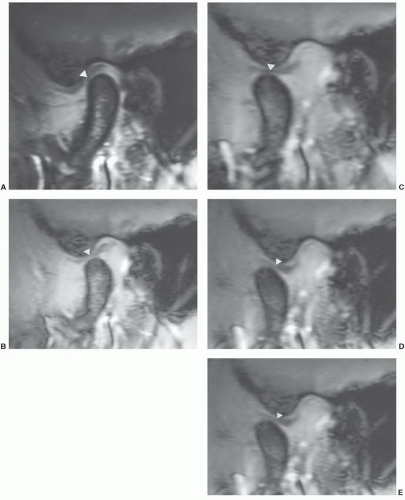 Figure 4.8 Sagittal gradient rephrasing echo (80/11/30° FA) images (A-E) demonstrating the position of the condyle and disc (arrowheads) progressing from closed (A) to open position (E). |
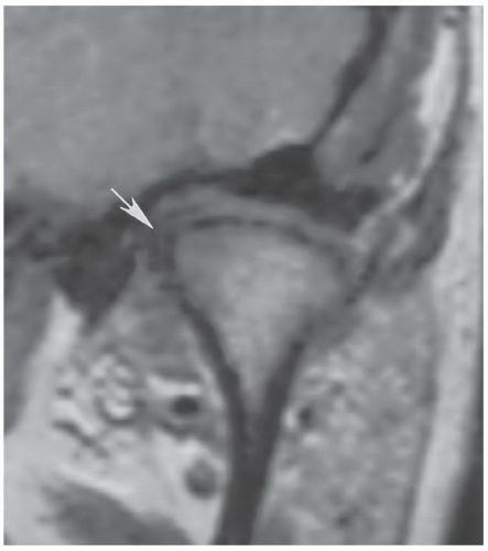 Figure 4.9 Coronal proton density (TSE 1,500/19) demonstrating a deformed disc with medial displacement (arrow). |
Suenaga et al.43 used a rapid bolus injection with T1-weighted fat-suppressed oblique sagittal images at 2, 4, 6, and 10 minutes to evaluate early synovial inflammation. In our practice, we rarely use intravenous gadolinium except in patients with rheumatoid arthritis or other early inflammatory arthropathies (Fig. 4.10). We have not used MR arthrography due to the time, cost, and difficulty that may occur with this invasive approach. However, MR arthrography does provide more information regarding adhesions, perforation, and posterior detachment.44
Toyama et al.44 evaluated 13 joints in 11 patients with MR arthrography. Needle position was confirmed with a small amount of iodinated contrast. A gadolinium solution (0.3 to 1.0 mL or 0.25 mmol per L) was injected into the lower (0.3 mL) and upper (0.5 mL) compartments. If a perforation was present, about 1 mL was injected to fill both compartments. Gadolinium was slowly injected into both the upper and lower compartments to avoid capsular rupture.
A perforation or posterior detachment was diagnosed when contrast flowed from one compartment to the next. Adhesions were diagnosed by incomplete filling of the injected compartment (Fig. 4.11). Surgical correlation was 100% for perforations. Accuracy for adhesions was 85% in the lower compartment and 77% in the upper compartment.44
INTERNAL DERANGEMENT
Internal derangement has been defined as an abnormal relationship or position of the disc in relation to the mandibular condyle and articular eminence.25,27,65 The etiology is uncertain; however, the condition is three to five times more common in women, and symptoms typically become evident by the fourth decade.25,65,66 Suggested etiologies include trauma, primary osseous abnormalities, mandibular asymmetry, malocclusion, bruxism, hypermobility, stress, and absence of the posterior teeth.3,21,67,68,69,


Related posts:

Stay updated, free articles. Join our Telegram channel
Full access? Get Clinical Tree
