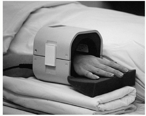
 Figure 11.1 Patient positioned with the arm at the side and supported for comfort. |
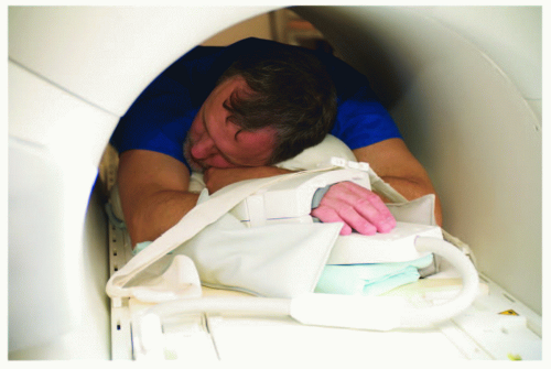 Figure 11.2 Patient positioned for evaluation of the hand and wrist using a circumferential (volume) coil. The arm is above the head. This position is not easily tolerated, and motion artifacts are likely to occur. Shoulder discomfort frequently develops early in the examination. |
the anatomy and characterize the lesion (Table 11.1). An effective screening examination can be accomplished by the beginning with either a coronal or sagittal scout (SE 500-400/10-20). This should include the full area of the hand and wrist to be examined. The sequences and image planes vary with clinical indication. One can begin with a standard screening examination and add additional sequences or gadolinium when indicated. T1- and T2-weighted sequences are performed. We use conventional spin-echo T1-weighted sequences and turbo spin-echo (FSE) T2-weighted sequences with fat suppression in most cases (Table 11.1). Conventional short TI inversion recovery (STIR) sequences have been replaced with FSE inversion recovery sequences. Fluid and pathologic tissues have high signal intensity in comparison to suppressed marrow and fat signal.
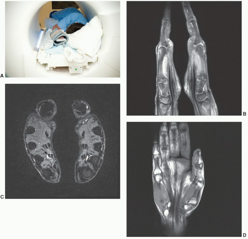 Figure 11.3 A: Photo of patient positioned in the lateral recumbent position with hands together in a “praying configuration” so both hands and wrists can be examined at the same time. Sagittal fat-suppressed proton density (B), STIR axial (C), and T1-weighted (D) images obtained in the “praying hands” position. Note the flexor tenosynovitis (arrow) on the left. |
anatomies, oblique planes are useful (Table 11.2). This is particularly true for the carpal bones (Fig. 11.8) and individual digits of the hand.
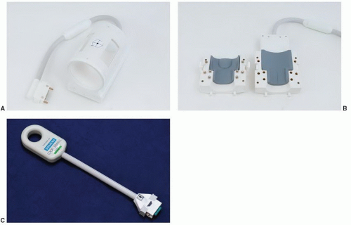 Figure 11.4 Coils for hand and wrist imaging. A: Volume quadrature coil. B: Opening volume coil. C: Digital coil for isolated wrist or finger imaging. |
Table 11.1 MR Techniques for Hand and Wrist Imaging at 1.5 T | ||||||||||||||||||||||||||||||||||||||||||||||||||||||||||||||||||||||||||||||||||||||||||||||||||||||||||||||||||||||||||||||
|---|---|---|---|---|---|---|---|---|---|---|---|---|---|---|---|---|---|---|---|---|---|---|---|---|---|---|---|---|---|---|---|---|---|---|---|---|---|---|---|---|---|---|---|---|---|---|---|---|---|---|---|---|---|---|---|---|---|---|---|---|---|---|---|---|---|---|---|---|---|---|---|---|---|---|---|---|---|---|---|---|---|---|---|---|---|---|---|---|---|---|---|---|---|---|---|---|---|---|---|---|---|---|---|---|---|---|---|---|---|---|---|---|---|---|---|---|---|---|---|---|---|---|---|---|---|---|
| ||||||||||||||||||||||||||||||||||||||||||||||||||||||||||||||||||||||||||||||||||||||||||||||||||||||||||||||||||||||||||||||
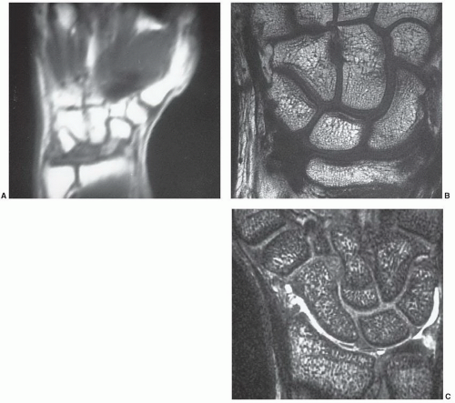 Figure 11.5 A: Coronal T1-weighted image of the wrist with a 24-cm FOV. T1-weighted image (B) and gradient-echo three-dimensional image (C) with 10-cm FOV. Note the marked improvement in image quality with a small FOV. |
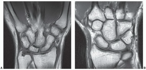 Figure 11.6 Coronal T1-weighted 1.5 T (A) and 3 T (B) images of the wrist. |
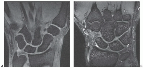 Figure 11.7 Coronal DESS 1.5 T (A) and 3.0 T (B) images demonstrating the articular cartilage. |
Table 11.2 MR Imaging of the Hand and Wrist: Image Planes | ||||||||||||||||||||
|---|---|---|---|---|---|---|---|---|---|---|---|---|---|---|---|---|---|---|---|---|
|
injected. We begin with the most symptomatic region or area of suspected pathology.7,35,36,37
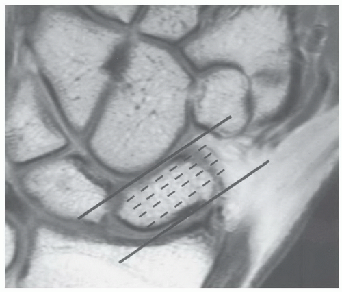 Figure 11.8 Coronal T1-weighted image demonstrating selection of oblique sagittal images to evaluate the scaphoid. |
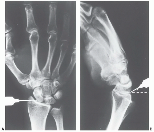 Figure 11.9 Injection site for the radiocarpal joint seen from the posteroanterior (A) and lateral (B) views. Flexing the wrist slightly facilitates needle placement. The needle is angled proximally. The region of the scapholunate ligament should be avoided. |
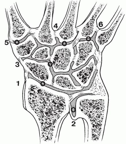 Figure 11.10 Injection sites for the radiocarpal (1), distal radioulnar joint (2), and intercarpal joint (3). The common carpometacarpal joint (4), first carpometacarpal joint (5), and outer carpometacarpal (6) joints are rarely injected. |
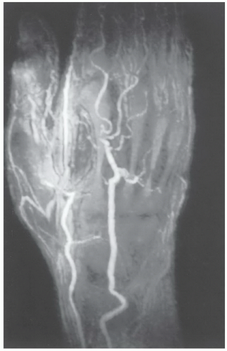 Figure 11.11 MR angiogram of the hand and wrist in a patient with vasculitis. There are multiple occlusions and vascular irregularities. |
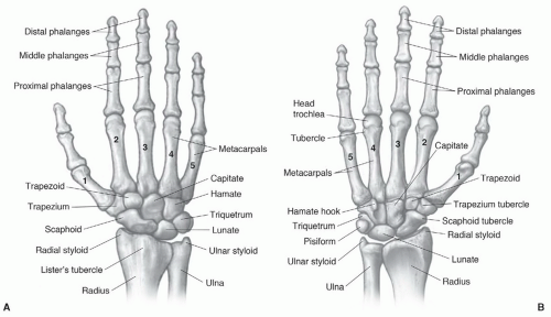 Figure 11.12 Osseous structures of the hand and wrist seen dorsally (A) and from the palmar surface (B). |
a ranking of 8 (range 1-9). Similar rankings are achieved for chronic wrist problems and soft tissue injuries.44,45
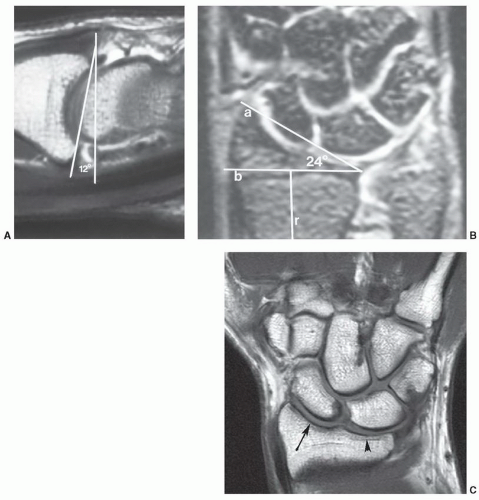 Figure 11.13 A: Sagittal MR arthrogram demonstrating the normal 12° palmar tilt of the distal radius. B: Coronal MR image demonstrating the normal radial inclination angle of 24°. The angle is formed by a line from the styloid tip to the articular margin (a) and a line (b) perpendicular to the radial shaft (r) at the level of the ulnar articular margin. C: Coronal 3.0 T T1-weighted image demonstrating the scaphoid (arrow) and lunate (arrowhead) fossae. |
surfaces of these bones should form a smooth, unbroken arch in the coronal plane. In the sagittal plane, the angle formed by the scaphoid and lunate should be between 30° and 60°. A second osseous anatomic group, or the distal carpal row, consists of the trapezoid, capitate, and hamate. The third compartment is composed of the trapezium and five metacarpals.21,46,56,58
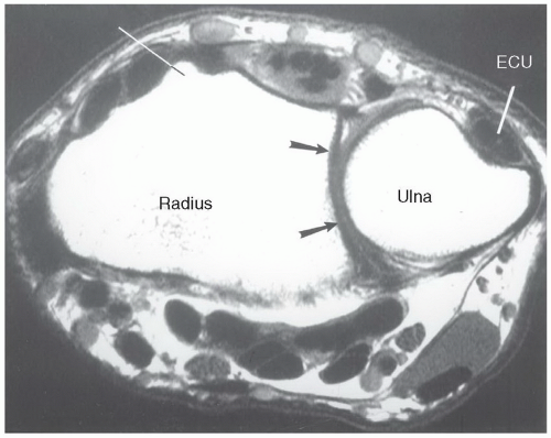 Figure 11.14 Axial T1-weighted image of the wrist demonstrating Lister tubercle, the sigmoid notch (arrows), and the groove in the dorsal ulna for the ECU. |
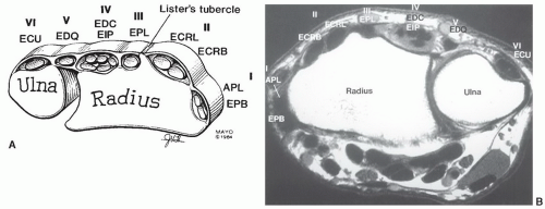 Figure 11.15 Illustration (A) and axial MR image (B) demonstrating the six dorsal compartments of the wrist. I, abductor pollicis longus (APL), extensor pollicis brevis (EPB); II, extensor carpi radialis longus (ECRL) and brevis (ECRB); III, extensor pollicis longus (EPL); IV, extensor digitorum communis (EDC) and extensor indicis proprius (EIP), V, extensor digiti quinti (EDQ); VI, extensor carpi ulnaris (ECU). |
capitate and hamate. These may be fibrous, cartilaginous, or osseous.62,64 A more complete discussion of osseous variants is included in the Pitfalls section of this chapter.
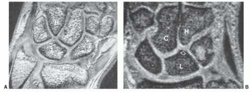 Figure 11.16 A: Coronal gradient-echo image demonstrating a type I (single facet) lunate articulating with the capitate. B: Coronal gradient-echo image of the lunate with a second small facet (open arrow, type II) articulating with the hamate. C, capitate; H, hamate; L, lunate. |
radioscapholunate were demonstrated in 66% and 26%, respectively. Three-dimensional techniques were used.
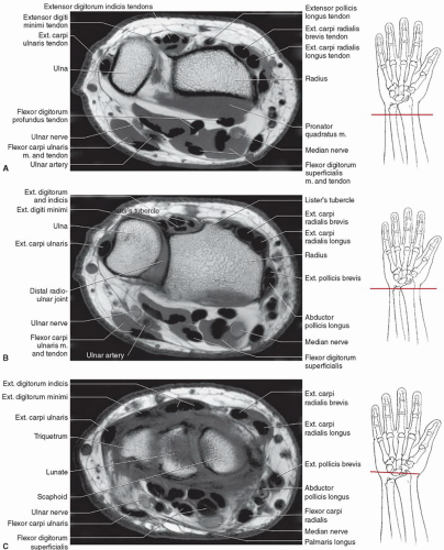 Figure 11.17 Axial images of the wrist and proximal hand with illustrations for plane of section. A: Axial images of distal forearm. B: Axial image through the distal radioulnar joint. C: Axial image through radiocarpal joint. D: Axial image through pisotriquetral joint and Guyon’s canal. E: Axial image through the distal carpal row and hamate hook. F: Axial image through the thenar region. G: Axial image through the metacarpals. H: Axial image through the base of the proximal phalanx. |
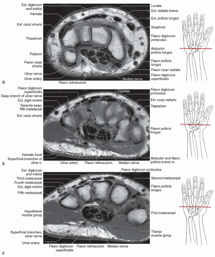 Figure 11.17 (continued) |
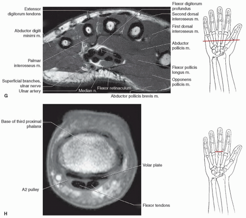 Figure 11.17 (continued) |
of patients. An amorphous appearance was noted in a few patients by Smith and Snearly (Fig. 11.24).50 Signal intensity is not always uniformly low, similar to variations described in the scapholunate ligament (Fig. 11.24).50,52
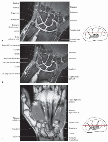 Figure 11.18 Coronal images of the hand and wrist with illustrations for plane of section. A: DESS image of the wrist. B: DESS image through the triangular fibrocartilage. C: Proton density-weighted image through the carpal bones and thenar muscles. D: Proton density-weighted image through the flexor tendons. E: T1-weighted image through the proximal interphalangeal joint. |
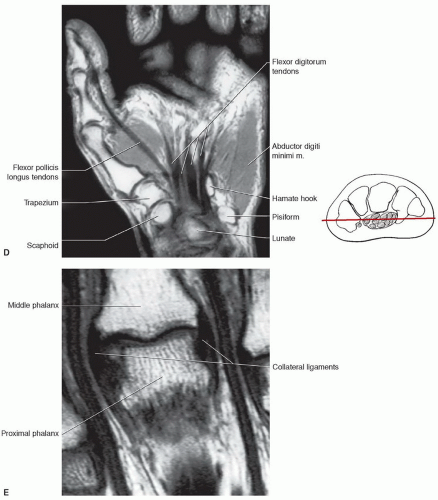 Figure 11.18 (continued) |
(Figs. 11.18E and 11.26).21,76 These ligaments are tight in extension and relax with flexion of the joints. The collateral ligaments are seen on axial and coronal MR images (Figs. 11.17 and 11.18). The palmar plate is clearly seen on axial and sagittal images.76
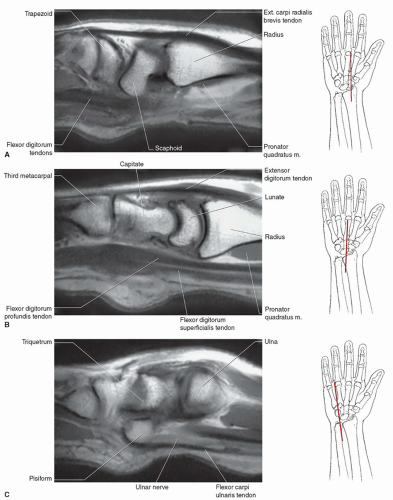 Figure 11.19 Sagittal images of the hand and wrist with illustrations for plane of section. A: T1-weighted image through the scaphoid. B: T1-weighted image through the lunocapitate region. C: T1-weighted image through the pisiform. D: T1-weighted image through the finger with pulley systems labeled. |
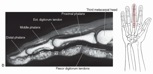 Figure 11.19 (continued) |
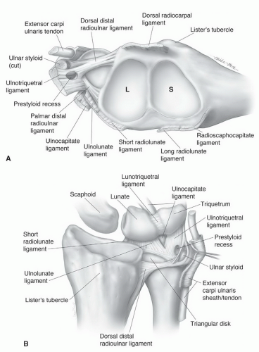 Figure 11.20 A: Distal radius including the scaphoid (S) and lunate (L) fossae and the TFCC. B: Ulnocarpal ligament complex and TFCC are seen dorsally. |
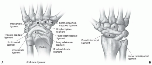 Figure 11.21 Palmar (A) and dorsal (B) carpal ligaments. 1, first metacarpal; 5, fifth metacarpal; Tm, trapezium; Td, trapezoid; C, capitate; H, hamate; P, pisiform; L, lunate; S, scaphoid; and T, triquetrum. |
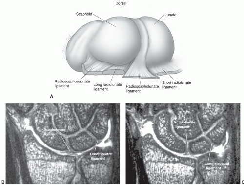 Figure 11.22 A: Scapholunate ligament from proximally and a slightly radial perspective. B and C: Coronal gradient-echo MR arthrogram images at different levels demonstrating variation in thickness of the scapholunate and lunotriquetral ligaments. |
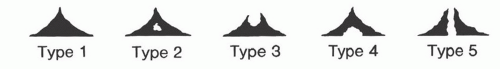 Figure 11.23 Signal intensity patterns in the scapholunate ligament described by Smith.52 Type I, uniform low signal intensity; type II, central intermediate signal intensity; type III, distal intermediate signal intensity; type IV, proximal intermediate signal intensity; type V, intermediate signal intensity extending through the ligament. |
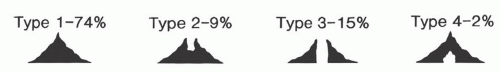 Figure 11.24 Signal intensity variations in the lunotriquetral ligament described by Smith and Snearly.50 Type I, homogenous low signal intensity; type II, distal intermediate signal intensity; type III, intermediate signal intensity extending through the ligament; type IV, proximal intermediate signal intensity. |
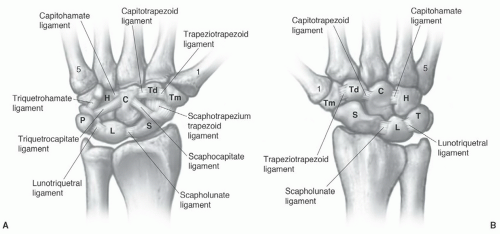 Figure 11.25 Palmar (A) and dorsal (B) intercarpal ligaments. |
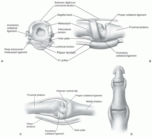 Figure 11.26 Metacarpophalangeal (A, B) and interphalangeal (C, D) joint anatomy. |
trapezoid. The muscle extends distally to form a tendon that inserts on the radial flexor side of the base of the proximal phalanx of the thumb. The primary function is flexion and rotation of the thumb. The opponens pollicis is partially covered by the abductors and flexors of the thumb and arises from the flexor retinaculum and trapezium to insert on the radial surface of the diaphysis of the first metacarpal. The adductor pollicis arises with both oblique and transverse heads. The transverse head arises from the ulnar surface of the third metacarpal diaphysis and the oblique head from the base of the third metacarpal and flexor aspects of the trapezium, trapezoid, and capitate. The triangular muscle extends to insert at the base of the proximal phalanx of the thumb. This muscle serves to adduct the metacarpal and flex the MCP joint of the thumb (Table 11.3).46,56
Table 11.3 Muscles of the Hand | ||||||||||||||||||||||||||||||||||||||||||||||||||||||||||||||||||||||
|---|---|---|---|---|---|---|---|---|---|---|---|---|---|---|---|---|---|---|---|---|---|---|---|---|---|---|---|---|---|---|---|---|---|---|---|---|---|---|---|---|---|---|---|---|---|---|---|---|---|---|---|---|---|---|---|---|---|---|---|---|---|---|---|---|---|---|---|---|---|---|
| ||||||||||||||||||||||||||||||||||||||||||||||||||||||||||||||||||||||
the hand to insert along the ulnar side of the base of the fifth proximal phalanx. This muscle abducts the little finger at the MCP joint. It acts along with the dorsal interosseous muscle to assist in abduction or spreading of the fingers. The flexor digiti minimi brevis arises more distally than the abductor digiti minimi and takes its origin from the hook of the hamate and flexor retinaculum. Thismuscle passes more obliquely and medially and inserts in the same position as the abductor. The main function of this muscle is as flexor of the fifth MCP joint. The third and final muscle of the deep hypothenar group is the opponens digiti minimi. This muscle is the deepest and arises deep to the abductor and flexor from the flexor retinaculum and distal hook of the hamate, taking an oblique course to insert along the ulnar aspect of the fifth metacarpal diaphysis. This muscle draws the fifth metacarpal anteriorly. All of the hypothenar muscle groups is innervated by the deep branch of the ulnar nerve (Table 11.3).46,56
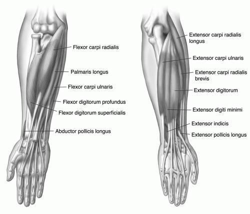 Figure 11.27 Flexor and extensor muscle groups. |
the pisiform level, the nerve and accompanying vascular structures lie between the volar carpal ligament and flexor retinaculum in a space commonly known as the Guyon’s canal.54,56 Lesions proximal to or within the canal can produce both sensory and motor abnormalities in the ulnar nerve distribution.54,56
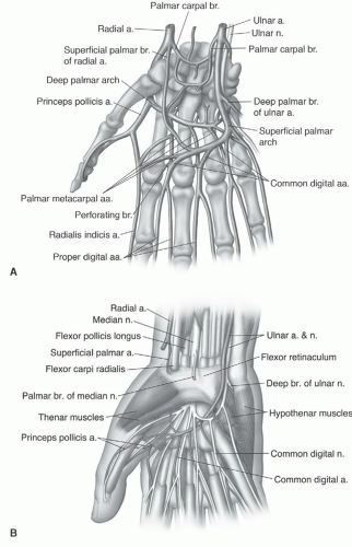 Figure 11.28 Vascular (A) and neurovascular (B) anatomy of the hand and wrist. |
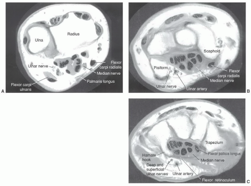 Figure 11.29 Axial MRI demonstrating the relationships of the ulnar and median nerves at the level of the distal radioulnar joint (A), pisiform (B), and hamate hook (C). |
do occur, they involve the most commonly fractured carpal bone, the scaphoid.56,62 The most common appearance is two separate ossicles separated at the waist, a common site of scaphoid fractures. The capitate and hook of the hamate may also develop from multiple ossification centers. When this occurs, differentiation from fracture may be difficult with MRI.63 Hypoplastic hamate hooks have been described in females.63,97
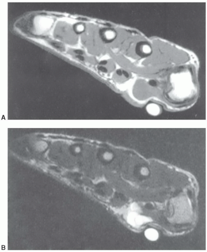 Figure 11.30 Axial T1- (A) and T2-weighted (B) images. The large vitamin E capsule compresses and distorts the underlying anatomy and ganglion cyst (arrow). |
Gruber-Ossiculum lies between the capitate, hamate, and the third and fourth metacarpal bases.62,64
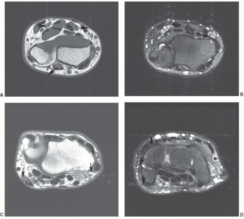 Figure 11.31 Axial 1.5 T T1-weighted (A) and T2-weighted (B) images demonstrating flow artifact (arrows) in the anteroposterior direction. The artifact is much more significant on the T2-weighted image (B). Axial 3.0 T T1-weighted (C) and T2-weighted (D) images demonstrating a change in phase direction with the artifact in the transverse direction. Again the artifact is slightly greater on the T2-weighted image. Phase direction can be swapped depending on the location of the lesion to avoid distortion of lesions from flow artifact. |
Muscle anomalies most commonly involve the abductor digiti minimi, palmaris longus, flexor carpi ulnaris, and flexor digitorum superficialis.96 Muscle anomalies are most often incidentally noted and do not cause symptoms.62,96
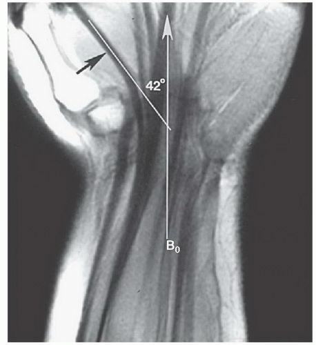 Figure 11.32 Coronal SE 500/10 image of the flexor tendons. Most tendons are oriented in the plane of this closed high field magnet (B0). The flexor pollicis longus is oriented 42° to B0. Magic angle phenomenon could come into play depending upon the degree of radial or ulnar deviation of the wrist. |
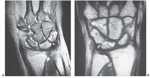 Figure 11.33 Lunotriquetral coalitions. A: Coronal T2-weighted image demonstrates a fibrous (type I) coalition. Note the low signal intensity and decreased joint space (arrow). The space is normal between the scaphoid and lunate and there is fluid in the joint space (open arrow). B: Coronal T1-weighted image demonstrating an osseous coalition with a proximal notch (arrow). T, triquetrum; L, lunate. |
Table 11.4 Common Ossicles of the Hand and Wrist | ||||||||||||||||||
|---|---|---|---|---|---|---|---|---|---|---|---|---|---|---|---|---|---|---|
| ||||||||||||||||||
aspect of the fifth proximal phalanx. Ulnar and median nerve symptoms have been associated with this anomaly (Fig. 11.39B).56,82,96
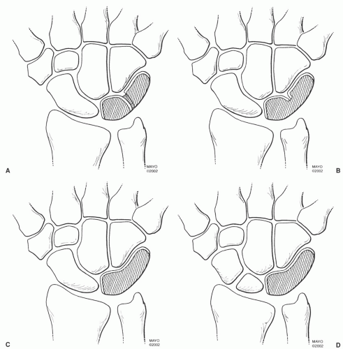 Figure 11.34 Lunotriquetral coalitions. A: Type I, fibrous or cartilaginous. B: Type II, incomplete osseous coalition with a distal notch. C: Type III, complete osseous fusion. D: Type IV, complete osseous fusion with other carpal anomalies, in this case a bipartite scaphoid. (From Berquist TH. MRI of the Hand and Wrist. Philadelphia, PA: Lippincott Williams & Wilkins; 2003.) |
infection. Also, confusion of tenosynovitis with a ganglion can occur. Most often, the common flexor tendon sheath ends in the mid palm (71.4% of the population). The digital sheaths in the fingers do not usually communicate with the common flexor tendon sheath.56
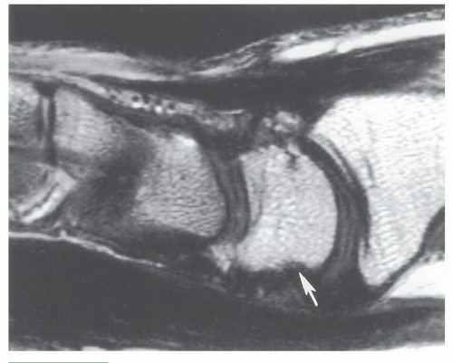 Figure 11.35 Sagittal T1-weighted image demonstrating volar irregularity of the lunate (arrow) due to normal ligament attachments. |
Table 11.5 Muscle Variants of the Hand and Wrist | ||||||||||||||||||||||||
|---|---|---|---|---|---|---|---|---|---|---|---|---|---|---|---|---|---|---|---|---|---|---|---|---|
| ||||||||||||||||||||||||
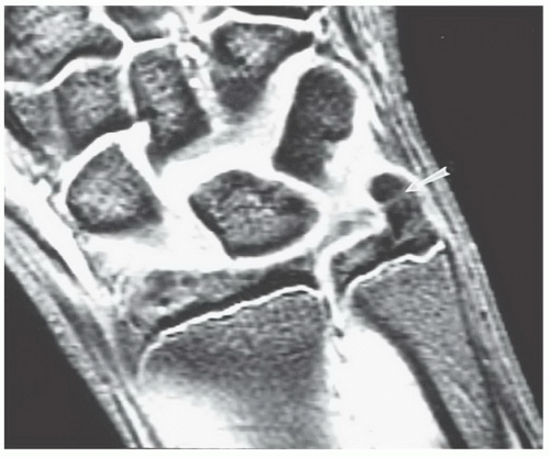 Figure 11.36 Coronal gradient-echo image demonstrating an elongated ulnar styloid with faint signal intensity increase (arrow) due to a partially fused lunula. |
in imaging other conditions in the hand and wrist. However, experience is still evolving in these areas.27,43,118,119,120
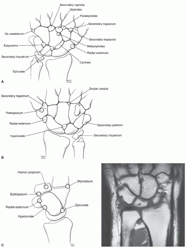 Figure 11.37 Ossicles of the wrist seen from dorsal (A), volar (B), and sagittal (C). Coronal T1-weighted image (D) demonstrates an os centrale (arrowhead). (From Berquist TH. MRI of the Hand and Wrist. Philadelphia, PA: Lippincott Williams & Wilkins; 2003.) |
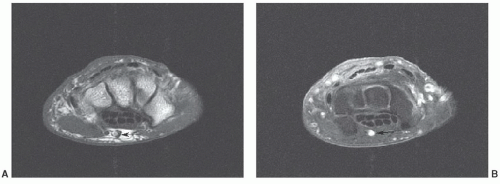 Figure 11.38 Axial T1-weighted (A) and post-contrast fat-suppressed T1-weighted (B) images demonstrating a persistent median artery (arrow). |
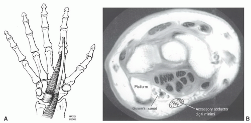 Figure 11.39 A: Accessory abductor digiti minimi. B: Axial MR image demonstrating the relationships of the muscle to Guyon’s canal. Normally, there is no muscle in this region. |
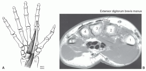 Figure 11.40 A: Extensor digitorum manus. B: Axial MR image demonstrating the location at the level of the metacarpal bases. The muscle is radial to the extensor tendons and between the second and third metacarpals. |
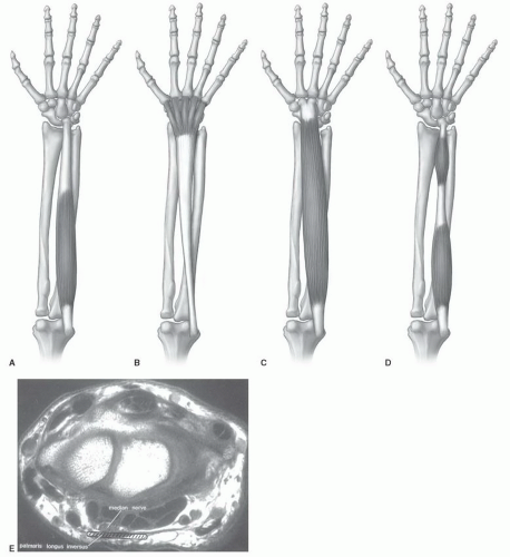 Figure 11.41 Palmaris longus muscle variations. A: Normal; B: inverse variant; C: total muscle variant; D: proximal and distal bellies. E: Axial MR image demonstrating the location of the palmaris longus inversus variant B at the radiocarpal joint. Note the relationship to the median nerve. |
include incomplete fractures, complete fractures, physeal fractures, stress fractures, and bone bruises.21,128,130,132,133
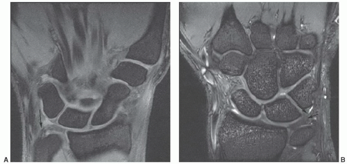 Figure 11.42 Coronal DESS images at 1.5 T (A) and 3.0 T (B) demonstrating intermediate to increased signal near the ulnar attachment of the triangular fibrocartilage in normal asymptomatic patients. |
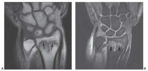 Figure 11.43 Distal radial fracture. Coronal T1- (A) and sagittal DESS (B) images demonstrate an undisplaced distal radial fracture (arrows) with marrow edema. |
carpal bone in adults and children. However, in children, scaphoid fractures account for only 2.9% of hand and wrist fractures. In adults, scaphoid fractures most commonly involve the waist, while in children the distal third is the most common fracture site (Fig. 11.44).134,138 Fractures of the triquetrum are the second most common carpal fracture followed by the capitate (Fig. 11.45) and lunate (Fig. 11.46).7,134
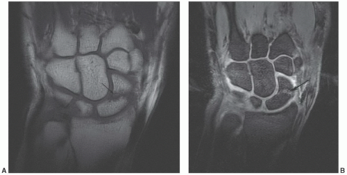 Figure 11.44 Scaphoid fracture. Coronal T1- (A) and DESS (B) images demonstrating a scaphoid waist fracture (arrow). |
important for the scaphoid (Fig. 11.48). Sagittal image planes aligned with the scaphoid are important to exclude “hump back” deformity.7
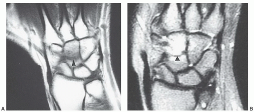 Figure 11.45 Capitate fracture. Coronal T1- (A) and T2-weighted (B) images of a capitate fracture (arrow). The fracture line is low signal intensity on both sequences. Edema is more obvious on the T2-weighted sequence. |
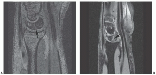 Figure 11.46 Lunate fracture. Sagittal gradient-echo (A) and fat-suppressed proton density (B) images demonstrate a lunate fracture (arrow). Fracture lines are usually most obvious in the sagittal plane. |
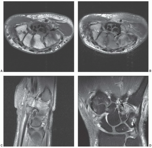 Figure 11.47 Hook of the hamate fracture with associated bone contusion in the triquetrum. Axial T1- (A) and axial (B) and sagittal (C)
Get Clinical Tree app for offline access
Related posts:Stay updated, free articles. Join our Telegram channel
Full access? Get Clinical Tree


|
