General Technical Considerations in Musculoskeletal MRI


General Technical Considerations in Musculoskeletal MRI


Thomas H. Berquist


Magnetic resonance imaging (MRI) is an excellent technique for evaluation of the musculoskeletal system.1,2,3,4,5,6,7 Respiratory motion, often a significant problem in the chest and abdomen, is generally not a problem in the spine, lower pelvis, and extremities.1,9 When motion artifact becomes an issue, specifically respiratory motion, new sequences and motion suppression techniques can be applied.4,5,8 MR images can be obtained in the coronal, sagittal, axial, and oblique planes. Radial (multiple oblique planes radiating from a central localization point) imaging techniques are also possible. Three-dimensional techniques are also available and particularly suited to areas where anatomy is complex.9,10,11,12,13

New coil technology, faster pulse sequences, and increased utilization of contrast agents have expanded the musculoskeletal applications for MRI.14,15,16,17 Arthrographic and angiographic techniques are now commonly employed.9,17,18,19,20,21,22,23,24,25,26 Spectroscopy is used more frequently, but it is still not routinely employed in day-to-day practice.27,28,29,30

New magnet designs, including higher field strengths [up to 8 Tesla (T)], open systems, and extremity systems, are also available (Fig. 3.1).1,17,31,32 Dedicated extremity units are less expensive and easily sited. Field strengths vary from 0.2 to 1.0 T. Positioning can be a problem with some patients, and the field of view (FOV) is limited compared with whole body systems.

As a rule, higher field strengths provide superior spatial and contrast resolution.1,31 Experience with 3 T and even higher field strengths (7 T) imaging is increasing.33 Signal-to-noise ratios (SNR) increase in a linear fashion with field strength. For example, the SNR at 3 T is twice that at 1.5 T. This allows increased spatial resolution without increasing imaging time. Chemical shift artifact is increased at 3 T, but this may be compensated by increasing the bandwidth. Fat suppression is alsomore uniformat 3 T compared with 1.5T. Ultrahigh-field strength imaging (7 to 9 T) is evolving and provides even greater spatial resolution, spectral resolution, imaging speed, and improved spectroscopic techniques.33 Today, most clinical musculoskeletal imaging is still performed at 1.5 T or lower field extremity or open magnets. Three-Tesla imaging is becoming more common at larger institutions.

MRI examinations must be conducted differently than radiographic or computed tomography (CT) studies. Patient selection, positioning, coil selection, pulse sequences, and use of intravenous or intra-articular contrast agents must all be considered prior to the examination to optimize image quality and properly characterize pathologic lesions. This chapter will discuss practical clinical concepts for musculoskeletal MRI. More specific techniques and applications will be discussed in the anatomic chapters that follow.


PATIENT SELECTION

MR images are produced using a static magnetic field, magnetic gradients, and radio frequency (RF) pulses (see Chapter 1). No ionizing radiation is used. To date, no untoward biologic effects have been identified at commonly used field strengths (≤2 T).34,35 MRI at 3 T and ultrahigh-field strengths (7 to 9 T) will require more investigation. However, to date, most patients tolerate examinations at these field strengths very well. A wider range of patient issues has been noted at 7 T, including vertigo and light flashes. Examination times are also increased at 7 T.36,37


PATIENT SCREENING: SAFETY ISSUES

Before considering MR as the method for imaging patients, certain screening issues and patient safety factors must be considered. The Safety Committee of the International
Society for Magnetic Resonance in Medicine recommends that each site or facility develop a standard policy for patient screening.38,39,40,41


Figure 3.1 Photographs of an extremity magnet (A) (courtesy of ONI Medical Systems, Inc., Willingham, MA) and an open magnet (B) (courtesy of Hitachi Medical Systems, Inc., Twinsburg, OH).

The screening methods may vary depending upon the type of facility, patient population (i.e., metal or construction workers, children, etc.), and allied health workers’ knowledge of MRI and potential risk factors.33,38,42,43

Most agree that a written questionnaire with specific, easily answered questions (Table 3.1) should be completed by patients and further verbal discussions also occur as the patient is being prepared for the examination. This should prevent overlooking obvious risk factors such as cardiac pacemakers, cerebral aneurysm clips, metallic foreign bodies, or electrical devices that may place the patient at risk during the examination. When metallic foreign bodies may be present, radiographs or, in some cases, CT should be obtained to confirm or exclude these potential problems. Boutin et al.38 reviewed safety data from 205 institutions and noted that 85% of departments used radiographs for screening (specifically for suspected foreign bodies in the orbit), 41% used CT, and 12% used metal detectors as a part of their patient screening program.38,42,43,44 Ongoing updates on MR safety have been produced by Shellock and colleagues.42,43

Magnetic fields may affect certain metal implants and electrical devices.1,39,56,59,64,66,67,69 In many situations, the exact metallic content of the implant cannot be determined.51 New electrical devices, pumps, and orthopedic implants continue to be developed requiring continued efforts to determine if these devices may place the patient at risk during an MR examination. Shellock and colleagues42,43 continue to update the impact of these devices for MRI on a regular basis. Devices are frequently labeled as MR safe or MR compatible. Confusion over the terminology led to further definition by the MR Task Group of the American Society for Testing and Materials International.42,72 The following new definitions are described by Shellock and Spinazzi.42


MR Safe

The device has no know hazard in any MR environment. MR safe items are nonmetallic, nonconducting, and nonmagnetic.42,72


MR Conditional

The device has been tested and does not pose any hazard in a specified MRI environment with specified conditions of use. The MR environment includes field strength, gradients, radiofrequency fields, and specific absorption rate. These devices are labeled indicating the testing results in an MR environment. Results should indicate current induction, heating, electromagnetic compatibility, neurostimulation, noise, interaction among devices and safe operation of the MR unit. Any parameter of the device that may affect safety should be clearly listed.


MR Unsafe

MR unsafe devices are devices known to pose hazards in any MR environment. This may be any ferromagnetic device or item.

Although evaluations are still in progress, many reports have defined a number of implants that may be potentially dangerous to the patient and/or affect image quality.1,42,49,51,53,56,57,58,59,63 Cardiac pacemakers have always been considered a contraindication for MRI. Concerns regarding pacemakers include inhibition, asynchronous pacing, patient discomfort, heating, and motion sensation at the implant site.73,74 In addition, significant image degradation may occur if the power pack is in the region being examined. Although some recent studies have demonstrated that pacemakers, implantable cardioverter defibrillators (ICD) show the potential that these devices may not be a
contraindication for MR, we and most other institutions continue to consider these devices as “MR unsafe.”74


Table 3.1 Safety Screening Questionnaire


Patient information


Medical record number:


Age:


Height:


Weight:


Claustrophobia. Yes__ No__


Latex allergy. Yes__ No__


Medication/contrast allergies. Yes__ No__ If yes, specify.


Have you had a previous MR examination. Yes__ No__ If yes, when and indication for exam?


Do you have a history of cancer? Yes__ No__ If yes, which type of cancer?


Have you had previous back surgery? Yes__ No__ If yes, when?


Have you had previous brain surgery? Yes__ No__ If yes, when?


Do you have a deep brain stimulator, Codman-Hakim, Stratta or programmable shut? Yes__ No__


Have you ever had an eye injury involving a metallic object? Yes__ No__


Female patients


Date of last menstrual period:_____


Could you be pregnant since the last menstrual period? Yes__ No__


Are you taking fertility medication, contraceptives, or hormone therapy? Yes__ No__


Breast feeding? Yes__ No__


Do you have any of the following?


Yes


No


1.


Cardiac pacemaker or defibrillator? (Stop and inform staff)


2.


Aneurysm clips in the head? (Stop and inform staff)


3.


Insulin or infusion pump? (Stop and inform staff)


4.


Implanted drug infusion device? (Stop and inform staff)


5.


Bone growth stimulator? (Stop and inform staff)


6.


Pessary? (Stop and inform staff)


7.


Internal pacing wires?


8.


Heart valve/stent prosthesis?


9.


Intravascular stents, filters, or coils?


10.


Swan-Ganz catheter and temp probe?


11.


Spinal or intraventricular shunt?


12.


Cochlear or ear implants?


13.


Hearing aid? (remove before examination)


14.


Any type of prosthesis (joint, bone, eye, penile)


15.


Transdermal drug delivery system?


16.


Tatooed makeup (eyeliner, lips, etc.)?


17.


Any metal fragments (bullet, shrapnel, BBs)?


18.


Any implant held in place by a magnet?


19.


Wire mesh implant?


Prior to the MRI scan, you will be asked to remove all clothing and change into a gown for the examination. Leave all personal belongings in your locked dressing room. Remember, most metal objects cannot be brought into the scanning suite.


Name (printed)_____________Signature______________


Form completed by: Patient__ Relative__ Other_____


Reviewed by: Nurse__ MRI technologist__ Radiologist__ Other__


From references 8, 38, 39, 41,42,43, 45,46,47,48,49,50,51,52,53,54,55,56,57,58,59,60,61,62,63,64,65,66,67,68,69,70,71.


In previous years, numerous heart valves have been studied at field strengths of 0.35 to 1.5 T. The artifacts created by most values were negligible, and it was concluded that patients with these prosthetic values can be safely imaged.60,64 However, movement or torque was demonstrated with certain valves. In spite of this response to the static magnetic field, the deflection is minimal and not considered a contraindication.56 More recently, prosthetic heart valves and annuloplasty rings have been studied at up to 3 T. The magnetic interactions are minimal even in elderly patients with age-related cardiac valve disease. Edwards et al.75 postulated that the stiffened tissue in elderly patients makes it even more difficult to cause valve sutures to dislodge.75,76 Therefore, hear valves and annuloplasty rings are not a contraindication for MR examinations. Patients with heart valves typically also have sternotomy
wires. Patients with sternotomy wires and retained epicardial pacemaker wires can be safely examined with MRI.64


Figure 3.2 MR artifacts created by hemostasis clips. A: 0.15-T SE 500/20 image in a patient with a partially resected liposarcoma. Note the focal areas of no signal with small bright halos (black arrowheads) caused by the surgical clip artifacts. B: 1.5-T SE 500/20 coronal images of the calves. Note the surgical clip artifacts (white arrowheads) in the right calf medially.

Early studies of cerebral aneurysm clips demonstrated significant torque and risk to the patient when exposed to an MR environment.47,56,66,67 Brown et al.47 demonstrated that the strongest torque and most significant image artifacts were present with clips made of 17-7HP stainless steel. Titanium and tantalum clips showed the least attractive force and minimal image distortion. Subsequent studies at up to 8 T have provided more information regarding patient safety and aneurysm clips.77,78,79 These studies also demonstrate that 17-7HP or 405 stainless steel aneurysm clips are an absolute contraindication for MRI.77,78 Aneurysm clips made from titanium alloy, pure titanium, austentitic stainless steel, or materials considered nonferromagnetic or weakly ferromagnetic are not a contraindication for MRI.77,78

Most surgical clips at our institution are nonferromagnetic or contain minimal ferromagnetic material. Nonferromagnetic surgical clips pose no risk to the patient and MR examinations can be performed in the immediate post-operative period.
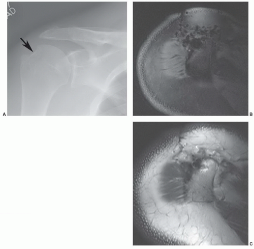
42 Nonferromagnetic or minimally ferromagnetic hemostasis clips may cause local image distortion, but do not pose a risk to the patient (Fig. 3.2). Shellock and Spinazzi42 recently reported several endoscopic hemostasis clips that may cause potential problems for patients undergoing MR examinations (Table 3.2).


Table 3.2 Gastrointestinal Endoscopic Hemostasis Clips with Labels Indicating MR Procedures May Be Harmful to the Patient


Resolution clip (Boston Scientific)


Long Clip HX-600-090L (Olympus Medical Systems)


QuickClip 2 (Olympus Medical Systems)


HX-201LR-135 (Olympus Medical Systems)


HX-201-UR-135 (Olympus Medical Systems)


QuickClip2 Long (Olympus Medical Systems)


HX-201LR-135L (Olympus Medical Systems)


HX-201UR-135L (Olympus Medical Systems)


From Shellock FG, Spinazzi A. MRI safety update 2008: Part 2, Screening patients for MRI. AJR Am J Roentgenol. 2008;191:1-10.


Other nonorth opedic metallic devices, including dental materials, ear implants, vascular filters and coils, genitourinary (GU) prostheses, ocular implants, and intrauterine devices, have also been investigated.48,52,60,61 Some removable dental plates are ferromagnetic and cause significant local artifact (Table 3.3).48,57 These materials should be removed prior to MRI.48 Permanent appliances such as braces may contain ferromagnetic material, but patients can be studied safely.57 The facial region is not included on most musculoskeletal MR images. Therefore, artifacts from dental appliances usually are not a problem. We do not examine patients with permanent dental prostheses held in with magnetic posts as it is not yet clear what effect the magnetic field will have on these components.1


Table 3.3 Dental Appliances: MR Image Artifacts


Material or Prosthesis


Artifact


Dental amalgam


No


Soft tissue conditioning material


No


Orthodontic wire


Yes


Type III gold


Yes


Type IV gold


Yes


Porcelain fixed to gold


No


Crown and bridge acrylic resin


No


Titanium implants


Yes


Polyurethane


No


Fixed partial denture, type III gold


Yes


Metal ceramic crown


Yes


Maxillary removable partial obturator


Yes


From Carr AB, Gibilisco JA, Berquist TH. Magnetic resonance imaging of the temporomandibular joint: preliminary work. J Craniomandib Disord. 1987;1(2):89-96; and Shellock FG, Myers SM, Kimble KJ. Monitoring heart rate and oxygen saturation with a fiber-optic pulse oximeter during MR imaging. AJR Am J Roentgenol. 1992;158:663-664.


Cochlear implants are, for the most part a contraindication for MR examinations as the device and the patient may be at risk. Specific implants may be MR compatible at lower field strengths, but to date we consider all such devices as “MR unsafe.”
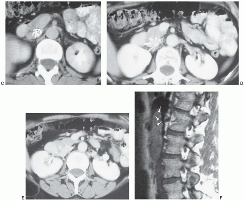
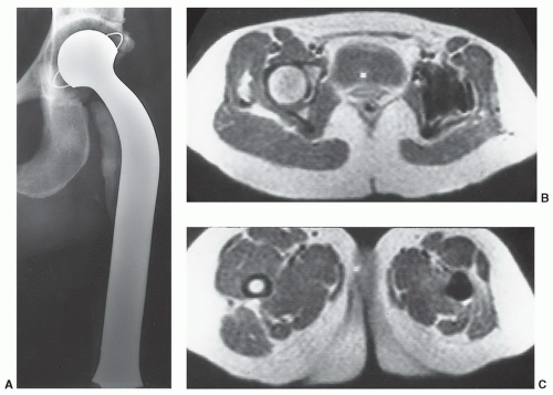
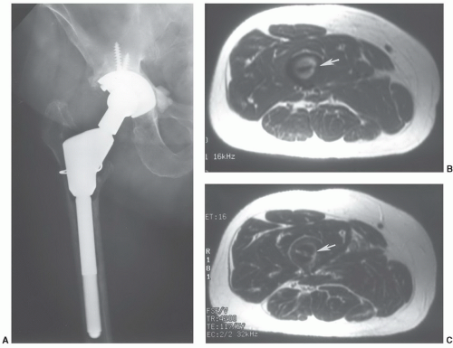
42,80

GU prostheses and vascular filters and coils, because of their location, are more likely to create artifacts and need to be considered carefully (Fig. 3.3). Most penile implants and GU sphincter prostheses do not contain significant ferromagnetic material. An exception is the Omni Phase (Dacomed) that contains significant amounts of metal.79 Shellock56 and Teitelbaum et al.63 studied vascular coils, stents, and filters in vitro and in vivo (Table 3.4). Their data indicate that artifact and torque are most significant with vascular appliances constructed with 304 and 316 stainless steel. Although the latter is not ferromagnetic in its original form, it does appear to undergo some change during configuration of appliances (i.e., Palmaz endostent). Materials creating minimal artifact include the appliances made with Beta-3 titanium, Elgiloy, nitinol, and mP32-N alloys.63 Despite their magnetic susceptibility and the degree of artifact created, patients with these devices generally can be imaged safely. The ferromagnetic devices (Greenfield filter, constructed of 316L stainless steel) did not displace or perforate the inferior vena cava (IVC).70 The position of devices containing ferromagnetic material [Gianturco embolization coil, Gianturco bird nest filter, Gianturco zigzag stent, Greenfield filter (316L stainless steel) and retrievable IVC filter, and Palmaz end ovascular stent] should be confirmed radiographically prior to examination. If the device is perpendicular to the magnetic field or immediately adjacent to the area of interest, the examination maybe inadequate and patient risk (due to change in position) is more significant.63,71 Shellock and Shellock69 evaluated 10 endovascular stents. They concluded that there was no significant interaction (motion or heating) with stents made of Elgiloy (cobalt, chromium, nickel, iron, and molybdenum), platinum-nickel, or tantalum.


Figure 3.3 Kimray-Greenfield vena cava filter. Anteroposterior (A) and lateral (B) radiographs of the lumbar spine demonstrate the caval filter at L1-L2. C-E: CT images demonstrate some streak artifact. F: Sagittal T1-weighted MR image demonstrates artifact (arrowheads) with trapped thrombus.

Multiple new cardiovascular devices were also evaluated by Levine et al.81 Permanent cardiac pacemakers, ICD, and heart valves were discussed previously. Therefore, we will focus on the other cardiovascular implants studied by these authors. Most coronary artery and peripheral vascular stents are configured of 316L stainless steel or nitinol. Other alloys
may also be used. However, most are nonferromagnetic or weakly ferromagnetic. Stents are implanted against the vessel wall and are well anchored. Although some studies suggest that MRI may be safer 6 to 8 weeks after the procedure, there is no strong clinical evidence to suggest delaying examination for this period is warranted. Therefore, most coronary and peripheral vascular stents come labeled as “MR safe” or “MRconditional.”81 Large aortic stents are also nonferromagnetic or weakly ferromagnetic and due not pose a risk to the patient. However, the artifact generated by certain grafts [Zenith AAA endovascular graft (Cook), Endologix AAA stent (Endologix), and Lifepath AAA stent (Edwards Life-sciences Corp.)] cause significant susceptibility artifact rendering the aortic examinations inadequate.81 IVC filters are configured of similar materials and may cause susceptibility artifact (Fig. 3.3) but have not been demonstrated to pose a patient risk. Full incorporation to the vessel wall occurs in 4 to 6 weeks.81 Care should be taken to include the product labeling in the patient record to avoid confusion regarding MR compatibility.


Figure 3.3 (continued)

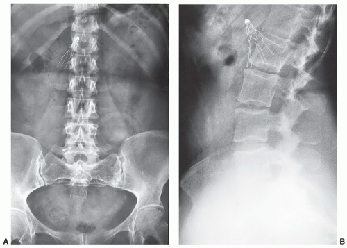
A potentially more difficult problem exists in patients with nonmedical foreign bodies or ferromagnetic material. Patients with shrapnel or other metal foreign bodies may not be aware that this material is present (Fig. 3.4). In this setting, there is little that can be done until an artifact is detected during the examination. If the patient expresses concern over a potential foreign body, one should consider a radiograph or CT (orbital foreign bodies) of the area or, if clinically indicated, cancel the examination.38 If an object is detected in the extremity and it is not near a nerve or in a region where its motion could cause damage, the examination can be performed with close monitoring
(technologist in the room, questioning the patient during and between pulse sequences). If the object has been present for 6 months or more, it will likely be fixated by scar tissue that reduces the risk of motion. Pigments in facial makeup (eyeliner, mascara, eye shadow) and certain tattoos may also contain ferromagnetic material (brown: ferric sulfate; flesh color: iron oxide; blue: cobalt chloride) and cause local heating and cutaneous inflammation.55 Patients with tattooed eyeliner are particularly susceptible. These factors should be considered, and avoiding these examinations may be indicated.


Table 3.4 Vascular Appliances: Construction Material and Artifacts


Device


Material


Company


Artifact


Greenfield filter


a) 316L stainless steel


Meditech, Watertown, MA


Significant


b) Beta-3 titanium


Ormco, Glendora, CA


Minimal—none


Mobin-Uddin IVC


Elginoy and silicone


American Edwards,


Mild


Umbrella


Rubber


Santa Ana, CA


Amplatz retrievable


MP 32N alloy


Cook, Bloomington, IN


Mild


IVC filter


Gunther retrievable


304 stainless steel


William Cook, Europe


Severe


IVC filter


Gianturco bird nest


304 stainless steel


William Cook, Europe


Severe


IVC filter


Retrievable filter


304 stainless steel


Thomas Jefferson University, Philadelphia, PA


Severe


Cragg nitinol spiral


Mild


IVC filter


Maass helical IVC filter


Mediloy stainless steel


Medinvent, Lausanne, Switzerland


Moderate


Maass endovascular


Mediloy stainless steel


Medinvent, Lausanne, Switzerland


Moderate


Palmaz endo stent


316 stainless steel


Ethicon, Summerville, NJ


Severe


GEC coil


304 stainless steel


Cook, Bloomington, IN


Severe


From Shellock FG, Myers SM, Kimble KJ. Monitoring heart rate and oxygen saturation with a fiber-optic pulse oximeter during MR imaging. AJR Am J Roentgenol. 1992;158:663-664; Teitelbaum GP, Ortega HV, Vinitski S, et al. Low-artifact intravascular devices: MR imaging evaluation. Radiology. 1988;168:713-719; and Theumann NH, Pfirrmann CWA, Antonio GE, et al. Extrinsic carpal ligaments: normal MR arthrographic appearance in cadavers. Radiology. 2003;226:171-179.


Figure 3.4 A: Radiograph of the elbow demonstrating a tiny metallic foreign body (arrow). T1-weighted (B) and T2-weighted (C) images demonstrate marked artifact due to a ferromagnetic foreign body.


Figure 3.5 A: Radiograph of a custom total hip arthroplasty demonstrating a large amount of metal in the hip and upper femur. B: Low-field (0.15 T) MR image at the femoral head level shows local distortion due to the size and configuration of the metal. C: In the region of the smaller smoother femoral stem there is no significant artifact on the low-field MR image.

Manufacturers of orthopedic appliances (plates, screws, joint prostheses, etc.) generally use high-grade stainless steel, cobalt-chromium, titanium, or multiphase alloys.1 These materials are usually not ferromagnetic but may contain minimal ferromagnetic impurities. Orthopedic appliances at our institution have been tested for magnetic properties (torque or twisting in the magnet) and heating. No heating or magnetic response could be detected.1,83 Davis et al.49 also studied the effects of RF pulses and changing magnetic fields on metal clips and prostheses. No heating could be detected with small amounts of metal. Heating was demonstrated with two adjacent hip prostheses in a saline medium. However, it was concluded that metal heating in patients should not be a problem even with a large prostheses.51,83 Heating and skin burns have occurred with looped or improperly positioned electrocardiogram (ECG) leads.

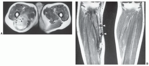
Nonferromagnetic metal materials may cause less significant artifacts on MR images and, if small enough, the insignificant area of signal void may be overlooked. The extent of metal susceptibility artifact created depends upon the size, shape, magnetic susceptibility, and field strength of the MR unit.
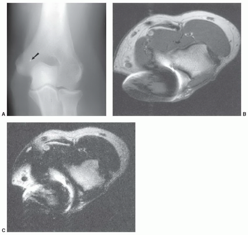
1,84 On low-field systems, some local distortion (Fig. 3.5) may be seen. The extent of artifact is usually more obvious on high-field (≥1 T) systems (Fig. 3.6). Many artifacts noted on MR images are due to local magnetic field distortions caused by both ferromagnetic and nonferromagnetic appliances. The degree of artifact is greater with the former. These distortions result in signal amplitude reduction near the metal surface.69 The artifacts generally is oriented in the direct of the frequency readout gradient.
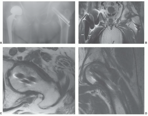
54,85,86

The artifacts created by orthopedic devices vary significantly. When imaging a hip prosthesis, there are more artifacts created by the large, irregular head and neck than the more regular and smaller femoral stem (Fig. 3.5). There are also more artifacts from metal screws and Harrington rods due to the contour irregularity of the implants
(Fig. 3.7).1,58 This may be due to the irregular contour (threads and ridges), screw position, or increased amounts of ferromagnetic impurities. Even small amounts of ferromagnetic materials can cause significant artifact.
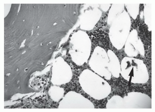
87 For example, histological evidence has demonstrated metal debris in histiocytes around screw tracts and drill tracts, suggesting that small amounts of ferromagnetic material are present in screws used for internal fixation. Drill bit fragments may also contribute to screw tract artifacts. A fibrohistiocytic response normally occurs around these screws if they are left in place for a significant length of time (>3 months). This phenomenon may allow artifacts to occur even though no significant metal can be detected on routine radiographs (Fig. 3.7).


Figure 3.6 A: Anteroposterior radiograph of the pelvis demonstrates a bipolar implant on the right and three cannulated hip screws on the left. B: Coronal T1-weighted image demonstrates marked artifact (compare to Fig. 3.5B at 0.15 T) in the region of the femoral head, but bone is clearly seen along the smoother femoral stem (arrows). There is less significant artifact along the smooth portion of the screws (arrowheads). There is slightly more artifact on the axial (C) and coronal (D) images along the threaded portion of the screws.

In recent years, multiple MRI parameter changes have been tested to reduce metal artifact.84 As 120,000 total hip procedures are performed each year in the United States, much of the effort has been directed at imaging of patients with hip arthroplasty (Figs. 3.5 and 3.6).8,85,86,87,88,89,90,91,92 Many of the same parameter modifications can be used regardless of the types of prostheses or fixation devices present.87,88,89,90,91,92 Parameter modifications include changes in the use of conventional pulse sequences (some improve and some exaggerate the artifact), slice thickness, matrix, band width, view angle tilting (VAT), newer metal artifact reduction sequences (MARS).87,88,89,90,91,92 Metal artifact is also increased with increased field strength.90


Figure 3.7 Histologic specimen of a screw tract with metal debris (arrow). (Courtesy of Les Wold, M.D., Department of Surgical Pathology, Mayo Clinic, Rochester, MN.)


Certain conventional pulse sequences demonstrate reduced artifact whereas others increase metal artifact. Short TE-(echo time) or T1-weighted spin-echo (SE) sequences reduce artifact. Fast short TI inversion recovery (STIR) sequences serve to increase signal intensity near the metal implant.87 Also, use of water excitation instead of fat suppression not only reduces artifact but also reduces imaging time by up to 50%.85


Figure 3.8 A: Anteroposterior radiograph of the shoulder demonstrates a defect in the humeral head (arrow) from prior rotator cuff repair. There are no identifiable metallic densities. Axial GRE (B) and T1-weighted (C) MR images demonstrate artifact due to microscopic drill bit debris. There is blooming on the GRE sequence (B).

Fast spin-echo (FSE) and gradient-echo (GRE) sequences create more artifacts about the implant. Blooming occurs about even minute metal debris with GRE sequences (Fig. 3.8).90,91,92 This misregistration artifact occurs only in the frequency-encoding direction. Misregistration artifact is proportional to the field inhomogeneity and inversely proportional to the frequency-encoding
gradient strength (Fig. 3.8). Artifact reduction can be achieved by increasing the frequency-encoding gradient and altering the frequency-encoding direction so that it is parallel to the metal object.90 This is often difficult to accomplish due to the multidirectional positions of plates and screws and rod and pedicle screw implants.


Figure 3.9 A: Anteroposterior radiograph of the hip with a custom right hip arthroplasty. Note the difference in image quality (arrow) when increasing the bandwidth from 16 kHz (B) to 32 kHz (C).

Increasing the bandwidth from 16 to 64 mHz has been shown to decrease the artifact about hip implants significantly (Fig. 3.9).87,90,91 Increasing the matrix size (equal to or greater than 256 × 256) and the number of acquisitions also decreases local image distortion around metal implants.91

Additional techniques for artifact reduction include VAT and MARS.90,92 VAT technique applies a compensatory gradient during image acquisition that corrects for local field inhomogeneity. MARS combines increased bandwidth and an added gradient during acquisition. These parameters are applied concurrently with the frequency-encoding gradient (Gx) and in the same direction and amplitude as the slice gradient (Gz). This sequence results in some loss of SNR, but reduces image blurring significantly.
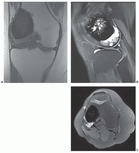
92

Methyl methacrylate and bone graft material is used to fill medullary cavities as well as to cement components. With the former, artifacts are minimal on MR images. Methacrylate is seen as a dark area of no signal, but there is no image distortion (Fig. 3.10).

External fixation devices may be bulky, but most are not ferromagnetic as the materials are similar to those used in internal fixators.1 Magnetic properties can be easily checked with a hand-held magnet prior to the MR examination. The extent of image degradation will vary with the magnetic susceptibility. Recently, manufacturers of fixators have begun to use nonferromagnetic material.1 Table 3.5 lists the materials used for external fixation devices in order of increasing artifact production on MR images.49 In addition to the artifact potential, coil selection may also be restricted due to the size of these fixation systems. This can result in a decreased SNR and reduced image quality. However, most patients can be examined using the head or body coils.

Evaluation of patients with casts and bulky dressings (Robert-Jones, etc.) is also possible with MRI. Although coil selection is more restrictive, we have not detected any reduction in image quality because of these materials.1


Figure 3.10 MR images of the upper tibia in a patient who had curettage of giant cell tumor with insertion of methyl methacrylate. Coronal T1-weighted (A), and sagittal (B) and axial (C) fat-suppressed FSE T2-weighted images demonstrate no artifact and recurrent tumor with an aneurismal bone cyst component (arrow in C).


PATIENT MONITORING AND SEDATION

The patient’s age, clinical status, and type and length of MR examination must be considered before determining if sedation, anesthesia, or pain medication will be required. Monitoring of physiologic parameters such as blood pressure, heart rate, skin temperature, respiratory rate, and oxygen saturation can all be evaluated safely during MR examinations.8,50,93 Whenever possible, examinations are performed without medication.

Most high-field MRI gantries are more confining than a conventional fluoroscopic unit or CT scanner. New short-bore, high-field systems are more easily tolerated by most patients. Mid- and low-field systems (0.02 to 0.5 T) with open gantries and extremity systems (Fig. 3.1) allow easier patient access and increased flexibility for patient positioning. These systems are better suited for claustrophobic and heavy patients. Patients are positioned in the center of the cylindrical or open-bore magnet chamber during the examination (Fig. 3.11). Despite the confined feeling that patients experience, sedation is only required in 3% to 4% of patients because of claustrophobia.1,

Only gold members can continue reading. Log In or Register to continue

Stay updated, free articles. Join our Telegram channel

May 25, 2016 | Posted by in RHEUMATOLOGY | Comments Off on General Technical Considerations in Musculoskeletal MRI

Full access? Get Clinical Tree

Get Clinical Tree app for offline access