Table 9.1 MR Examinations of the Shoulder, Arm, and Brachial Plexus at 1.5 T | |||||||||||||||||||||||||||||||||||||||||||||||||||||||||||||||||||||||||||||||||||||||||||||||||||||||||||||||||||||||||||||||||||||||||||||||||||||||||||||||||||||||||||||||||||||||||||||||||||||||||||
|---|---|---|---|---|---|---|---|---|---|---|---|---|---|---|---|---|---|---|---|---|---|---|---|---|---|---|---|---|---|---|---|---|---|---|---|---|---|---|---|---|---|---|---|---|---|---|---|---|---|---|---|---|---|---|---|---|---|---|---|---|---|---|---|---|---|---|---|---|---|---|---|---|---|---|---|---|---|---|---|---|---|---|---|---|---|---|---|---|---|---|---|---|---|---|---|---|---|---|---|---|---|---|---|---|---|---|---|---|---|---|---|---|---|---|---|---|---|---|---|---|---|---|---|---|---|---|---|---|---|---|---|---|---|---|---|---|---|---|---|---|---|---|---|---|---|---|---|---|---|---|---|---|---|---|---|---|---|---|---|---|---|---|---|---|---|---|---|---|---|---|---|---|---|---|---|---|---|---|---|---|---|---|---|---|---|---|---|---|---|---|---|---|---|---|---|---|---|---|---|---|---|---|---|
| |||||||||||||||||||||||||||||||||||||||||||||||||||||||||||||||||||||||||||||||||||||||||||||||||||||||||||||||||||||||||||||||||||||||||||||||||||||||||||||||||||||||||||||||||||||||||||||||||||||||||||
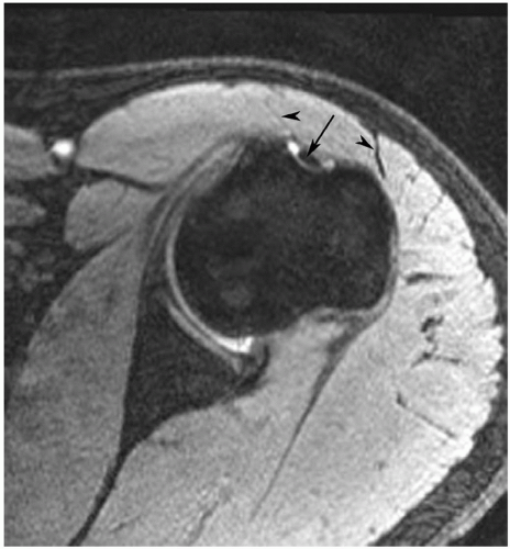 Figure 9.1 Axial gradient-echo image of the shoulder at 3.0 T with the arm positioned with the hand palm up. Note the position of the bicipital groove arrow. If internally rotated the groove would move medially (medial arrowhead) and if too externally rotated it would move laterally (lateral arrowhead). |
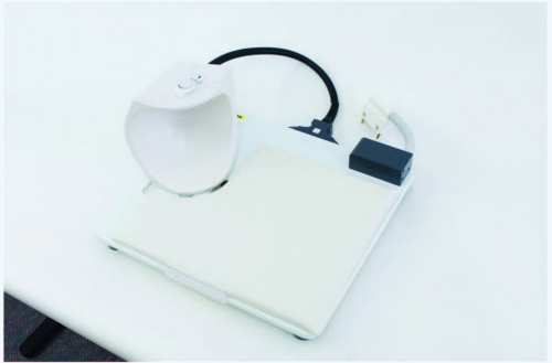 Figure 9.2 Phased array shoulder coil. (Courtesy of Siemens Medical Systems, Erlangen, Germany.) |
appreciated and classified. Signal intensity in the rotator cuff increases from proton density to T2-weighted images when partial or complete cuff tears are present. Signal intensity does not increase significantly in areas of tendinosis on T2-weighted sequences.25,26,27
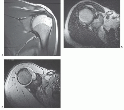 Figure 9.3 A: Coronal proton density weighted image demonstrating the region of interest covered with 14 cm field of view MRI. The area from above the acromioclavicular joint to below the axillary recess should be included. B: Axial SE 2,000/80 image degraded by motion artifact. C: Multiplanar gradient-echo (700/31, flip angle 25°) image in the same patient. There is no motion artifact. |
capsular distention that aids delineation of the labroligamentous structures.
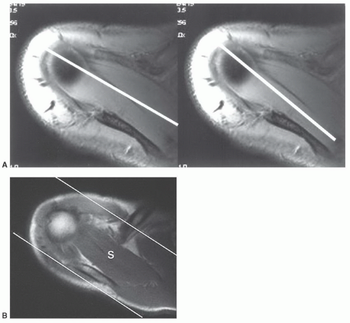 Figure 9.4 A: Image planes selected for coronal images along the axis of the supraspinatus muscle (left) or central supraspinatus tendon (right). B: Axial MR image demonstrating the area covered along the axis of the supraspinatus (S). |
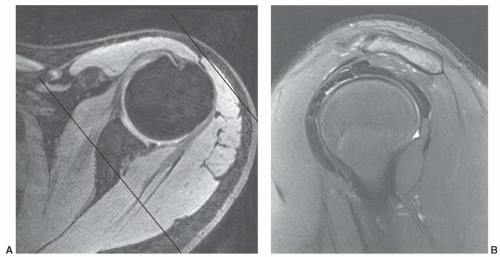 Figure 9.5 A: Axial 3.0 T image demonstrating the image planes (lines for area covered) for oblique sagittal imaging. B: Sagittal 3.0 T turbo spin-echo fat suppressed image demonstrating a normal supraspinatus muscle and rotator cuff tendons. The acromion is straight. |
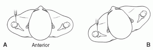 Figure 9.6 Illustrations of anterior injection sites with the patient supine (A) and slightly rotated (B). |
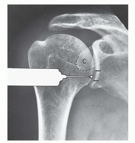 Figure 9.7 Illustration of injection site for MR arthrography using the anterior inferior approach. (From Berquist TH. Imaging of Orthopedic Trauma, 2nd ed. New York: Raven Press; 1992.) |
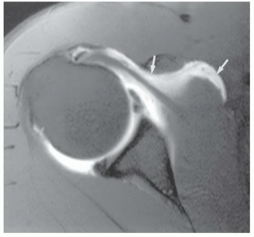 Figure 9.8 Axial MR arthrogram image demonstrating anterior contrast extravasation (arrows). |
rotated superiorly to align the glenohumeral articular surface. Patient position is supported by bolsters. After sterile preparation, the skin is marked over the lower medial humeral head. Following anesthetic injection, a spinal needle is advanced vertically until it contacts the humeral head. Intra-articular position is confirmed with iodinated contrast.51,53
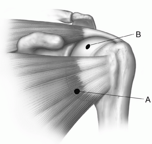 Figure 9.9 Illustration of the typical anterior injection site (A) through the subscapularis and higher (B) in the rotator cuff interval between the subscapularis and supraspinatus. |
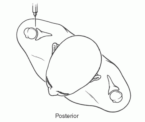 Figure 9.10 Illustration of patient positioned for posterior injection. |
or proximal nerve root abnormalities. These techniques are fully discussed in Chapter 5. Evaluation of the brachial plexus requires images from the mid cervical spine to the humerus, so a large FOV is necessary (Fig. 9.12). A torso coil is commonly employed. If symptoms are unilateral, a smaller off-center FOV can be used. Comparison is helpful, so we often examine both brachial plexus regions simultaneously. The axial images (right, left, or bilateral) are obtained using cardiac and respiratory gating to minimize the artifact from respiratory and cardiac motion. Slice thickness of 5 mm with 1.5-mm skip and an 18- (unilateral) or 36±-(bilateral) cm FOV with 256 × 256 matrix and 1 to 2 acquisitions are commonly used. Axial images are usually obtained from the mid cervical level (C3-C4) to the mid humerus, which allows the lower neck, shoulder, and upper arm to be completely included in the FOV (Fig. 9.13).
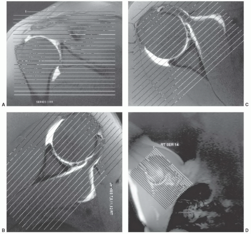 Figure 9.11 MR arthrogram. Scout images for the axial (A), oblique coronal (B), oblique sagittal (C), and abduction-external rotation (ABER) view (D). Normal axial (E-G), coronal (H, I), sagittal (J-L), and ABER (M) images. |
bundle. In most situations, the axial and sagittal images provide an adequate screening examination for brachial plexus pathology. We typically add coronal and axial turbo inversion recovery (TIR) images (Fig. 9.15). Post-contrast fat-suppressed T1-weighted images are useful for evaluation of neural inflammation and characterizing adjacent masses or soft tissue abnormalities. Technical details are discussed in depth in the clinical applications section of this chapter.
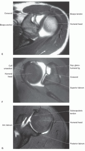 Figure 9.11 (continued) |
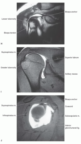 Figure 9.11 (continued) |
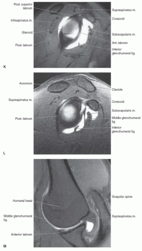 Figure 9.11 (continued) |
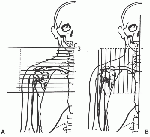 Figure 9.12 Illustration of area studied with axial (A) and sagittal (B) imaging of the brachial plexus. |
glenohumeral ligament. The transverse ligament extends across the greater and lesser tuberosities, enclosing the synovial sheath and long head of the biceps tendon.69,70,71
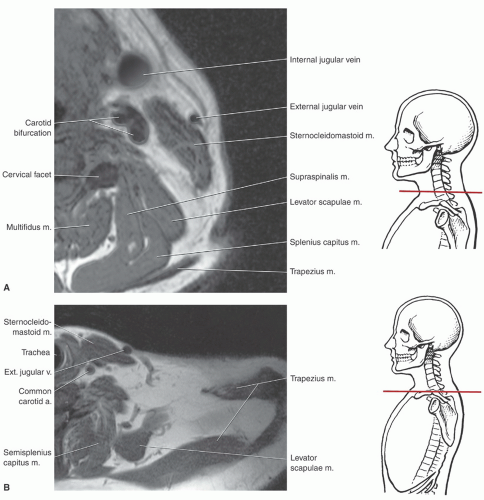 Figure 9.13 Axial images of the brachial plexus region with anatomic levels indicated. A: Axial image through the lower cervical region. B: Axial image at the base of the neck. C: Axial image through the upper humeral head. D: Axial image through the glenohumeral level. E: Axial image through the upper arm and axilla. |
with rotator cuff tears.4,12,64,72 The supraspinatus muscle arises from the supraspinous fossa of the scapula and is covered by the trapezius in its proximal portion. As the muscle extends peripherally, it passes under the acromion, coracoclavicular ligament, and AC joint (Fig. 9.25) to insert on the most superior of the three facets of the greater tuberosity. Tendon of the supraspinatus is broad, covering the top of the shoulder and blending with the capsule superiorly. The primary function of the supraspinatus is to assist the deltoid in abduction of the humerus (Table 9.2).61,69,73,74
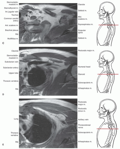 Figure 9.13 (continued) |
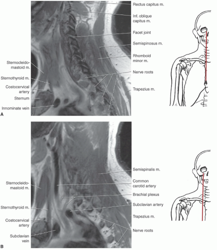 Figure 9.14 Sagittal images of the brachial plexus region with anatomic levels indicated. A: Sagittal image through the facets and intervertebral foramina. B: Sagittal image through the carotid artery. C: Sagittal image through the lateral neck. D: Sagittal image through the lateral chest. |
separated from the scapula by a bursa that sometimes communicates with the shoulder joint (Table 9.3). The infraspinatus is separated from the supraspinatus by the scapular spine (Figs. 9.16,8.17,9.18). Its tendon forms the upper posterior portion of the rotator cuff and inserts in the greater tuberosity posterior and inferior to the supraspinatus tendon.69,72,75,76,77,78
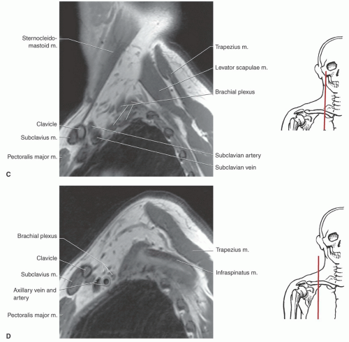 Figure 9.14 (continued) |
passing across and anterior to the muscle (Fig. 9.26). The subscapularis bursa or recess lies between the muscle and the neck of the scapula and can communicate with the shoulder joint (Table 9.3). The primary function of the subscapularis is internal rotation of the humerus (Table 9.2).61,69
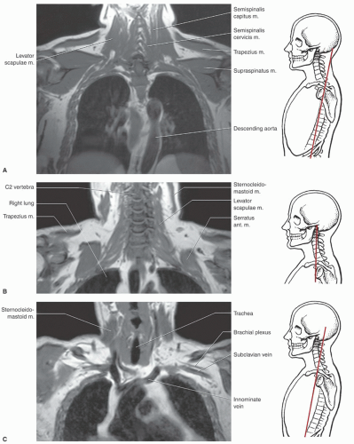 Figure 9.15 Coronal images of neck and shoulders with anatomic levels indicated. A: Coronal image through the descending aorta. B: Coronal image through the cervical spine. C: Coronal image through the neurovascular region. |
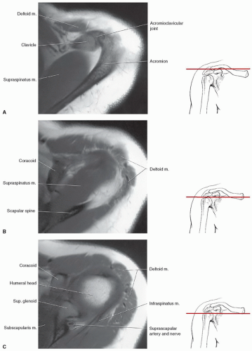 Figure 9.16 Axial MR anatomy of the shoulder with illustration of anatomic levels. A: Axial image through the acromioclavicular joint. B: Axial image through the supraspinatus. C: Axial image through the upper glenoid and coracoid. D: Axial image through the humeral head and glenoid demonstrating the normal labrum. E: Axial image through the lower glenoid. |
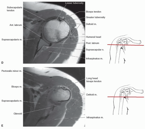 Figure 9.16 (continued) |
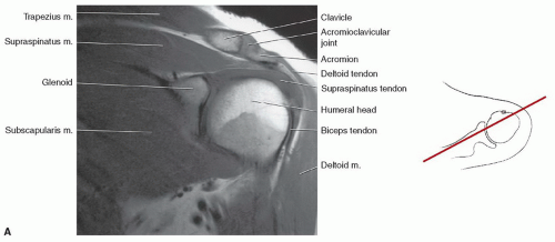 Figure 9.17 Coronal MR images of the shoulder with illustration of the section levels. A: Coronal image through the humeral head and acromioclavicular joint. B: Coronal image through the glenohumeral joint. |
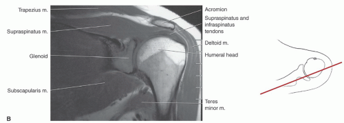 Figure 9.17 (continued) |
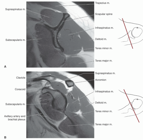 Figure 9.18 Sagittal MR images of the shoulder with level of section indicated. A: Sagittal image through the scapular spine. B: Sagittal image through the coracoid. C: Sagittal image through the glenoid articular surface. D: Sagittal image through the humeral head and acromioclavicular joint. E: Sagittal image through the lateral humeral head. |
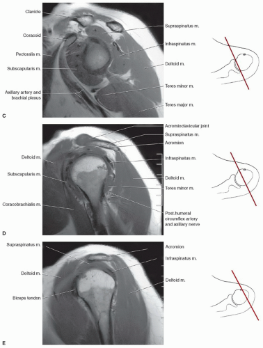 Figure 9.18 (continued) |
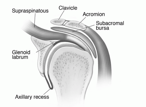 Figure 9.19 Illustration of the shoulder, demonstrating the glenohumeral and acromioclavicular joints and surrounding structures. |
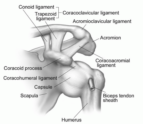 Figure 9.20 Illustration of the ligaments of the shoulder. |
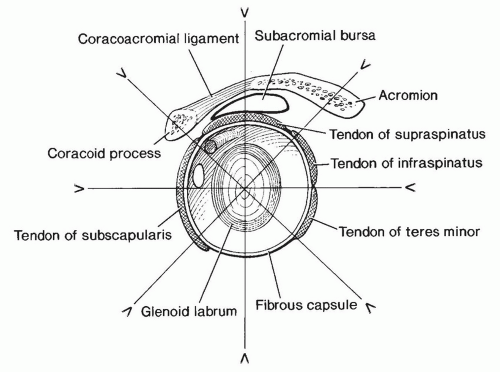 Figure 9.21 Illustration of the shoulder, demonstrating the glenoid articular surface, labrum, and supporting structures. Radial image planes and labral configuration are demonstrated. |
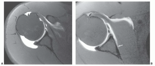 Figure 9.22 Capsular attachments. A: Axial MR arthrogram image of the shoulder demonstrating the capsular attachments. There is a type I attachment anteriorly and more medial type II attachment posteriorly with capsular distention. B: Axial MR arthrogram image demonstrating a type I posterior attachment and type III anterior attachment (arrow). |
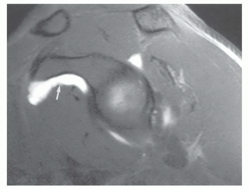 Figure 9.23 Sagittal MR arthrogram shows the subcoracoid bursa (arrow). |
pectoralis major is a large, triangular, flat muscle covering much of the upper thorax. The pectoralis major has an extensive origin from the medial inferior aspect of the clavicle, the lateral margin of the sternum, and the chondral junctions of the upper ribs. The fibers of this muscle converge to form a broad tendon that passes just anterior to coracobrachialis and biceps brachii. The muscle then passes deep to the anterior margin of the deltoid to insert on the crest of the greater tubercle or lateral aspect of the intertubercular groove. The pectoralis major is a strong adductor of the humerus and is innervated by two nerves, the lateral and medial (anterior thoracic) nerves (Table 9.2).61,69
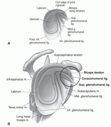 Figure 9.24 Illustration of the glenohumeral ligaments (A) and their relationship to the coracohumeral ligament (B). |
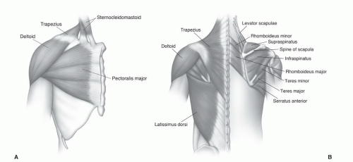 Figure 9.25 Illustrations of the extrinsic shoulder muscles from anterior (A) and posterior (B). |
Table 9.2 Muscles of the Shoulder and Upper Arm | |||||||||||||||||||||||||||||||||||||||||||||||||||||||||||||||||||||||||||||||||||||||||||||||||||||||||
|---|---|---|---|---|---|---|---|---|---|---|---|---|---|---|---|---|---|---|---|---|---|---|---|---|---|---|---|---|---|---|---|---|---|---|---|---|---|---|---|---|---|---|---|---|---|---|---|---|---|---|---|---|---|---|---|---|---|---|---|---|---|---|---|---|---|---|---|---|---|---|---|---|---|---|---|---|---|---|---|---|---|---|---|---|---|---|---|---|---|---|---|---|---|---|---|---|---|---|---|---|---|---|---|---|---|
| |||||||||||||||||||||||||||||||||||||||||||||||||||||||||||||||||||||||||||||||||||||||||||||||||||||||||
to insert on the coracoid process of the scapula. Its chief action is to depress the angle of the scapula. Nerve supply is via the medial pectoral nerve (C8-T1) (Table 9.2).61
Table 9.3 Shoulder Bursae | ||||||||||||||||||||||||||||||||||||
|---|---|---|---|---|---|---|---|---|---|---|---|---|---|---|---|---|---|---|---|---|---|---|---|---|---|---|---|---|---|---|---|---|---|---|---|---|
| ||||||||||||||||||||||||||||||||||||
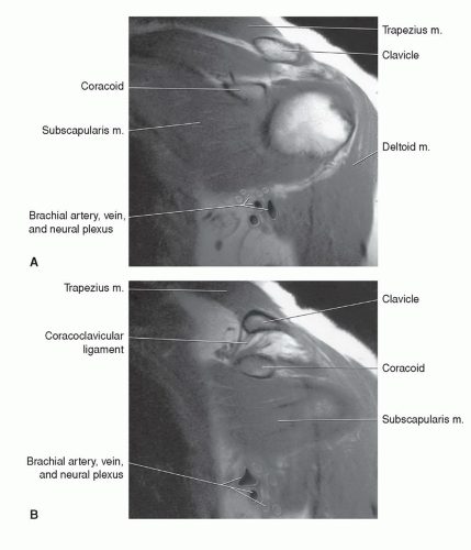 Figure 9.26 A and B: Coronal T1-weighted images through the anterior shoulder, demonstrating the subscapularis and adjacent neurovascular structures. |
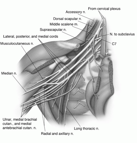 Figure 9.27 Illustration of the brachial plexus and branches. |
(Figs. 9.14 and 9.15). At this level, the lateral cord and a major portion of the posterior cord lie lateral and superior to the axillary artery. The lower trunk of the medial cord is posterior to the artery, with the major continuation of the other groups in close approximation to the vessel (Figs. 9.15 and 9.27). On sagittal images, this forms a closely approximated group of low-intensity structures (Fig. 9.14).6,59,61,69
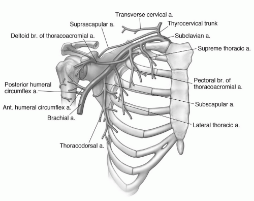 Figure 9.28 Illustration of the vascular anatomy in the axillary region. |
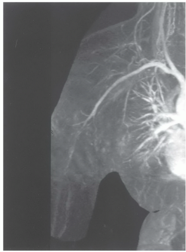 Figure 9.29 Coronal MR angiogram of the neck and shoulder. |
occur less frequently in the shoulder compared to the elbow and wrist. Motion artifacts may be related to pain, tremor, respiratory motion, or forced external or abduction-external rotation, which may be difficult positions to maintain (Fig. 9.30).2,85 Motion artifacts can be reduced by increasing patient comfort, positioning, and using faster sequences to reduce imaging time.2,12 Flow artifacts are a less significant problem. Artifact occurs in the phase encoding direction. Therefore, phase encoding directions should be selected on the basis of the suspected pathology. A transverse phase encoding should be selected for rotator cuff disease (Fig. 9.31) to reduce confusion that may occur when flow artifact is in the superior-inferior direction that would pass through the rotator cuff.2,89
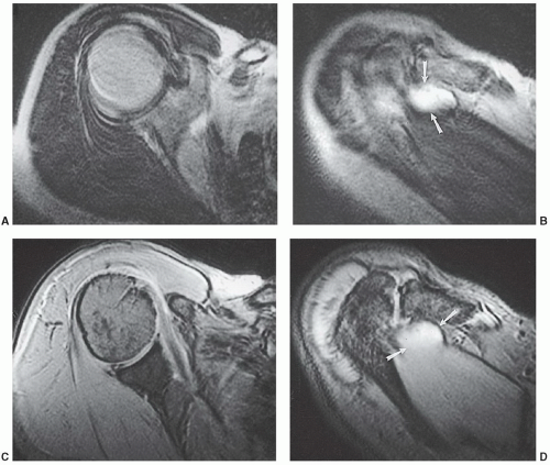 Figure 9.30 Axial T2-weighted (A and B) and gradient-echo (C and D) images in a patient with a rotator cuff tear (arrows). There is motion artifact that degrades image quality on conventional spin-echo sequences A and B. No significant artifact is evident on the gradient-echo sequences C and D. |
example, Theodoropoulos et al.84 demonstrated significant performance differences comparing musculoskeletal trained radiologists and general radiologists for technique and interpretation. Improper injection of contrast can result in extravasation (Fig. 9.8), which can be confused with pathology.50,81,83,84 Inadvertent injection of air bubbles may cause areas of low signal intensity on MR arthrograms that mimic loose bodies. “Blooming” may cause the air bubble to appear larger due to magnetic susceptibility artifact. This phenomenon is more common on GRE images.81
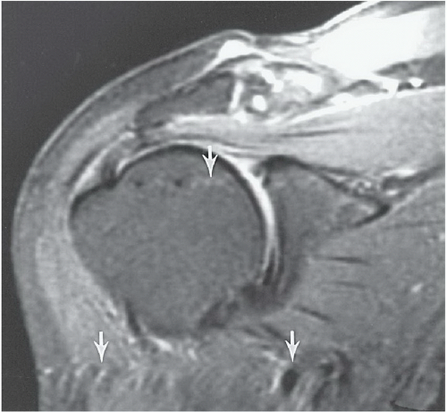 Figure 9.31 Coronal T2-weighted fast spin-echo image with fat suppression. The flow artifact (arrows) runs transversely. |
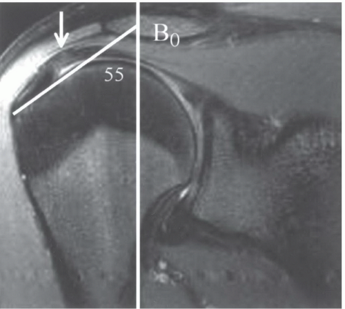 Figure 9.32 Coronal SE 500/11 sequence demonstrating increased signal (white arrow) in the supraspinatus that is angled at 55° to the magnet bore (white line). |
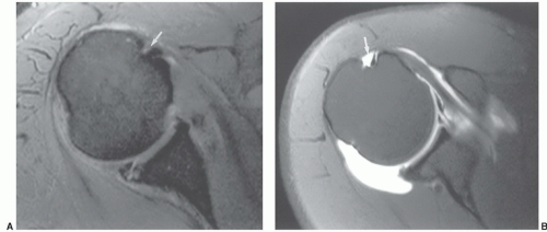 Figure 9.33 Axial gradient-echo image (A) with the bicipital groove (arrow) position indicating slight internal rotation. Axial MR arthrogram (B) shows more external rotation with the groove (arrow) more lateral and a stretched subscapularis. |
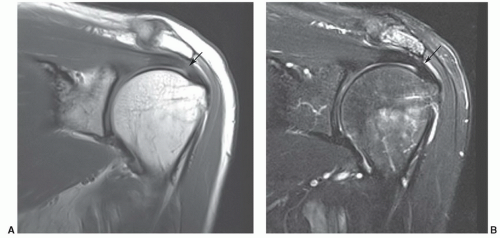 Figure 9.34 50-year-old male. Turbo spin-echo proton density (A) and T2-weighted (B) images demonstrate an area of intermediate signal intensity near the insertion (arrow) in A. The signal intensity does not increase on the T2-weighted sequence (arrow in B). |
subdeltoid bursa can also be detected in patients without an associated rotator cuff tear.73,97 However, other conditions such as impingement, bursitis, and tendinitis may be associated with fluid in the bursa.47 Fat-suppression techniques may be useful to reduce problems caused by chemical shift artifacts that occur at fat-water interfaces.73,97
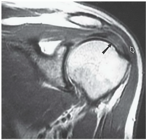 Figure 9.35 Coronal proton density image with increased signal in the supraspinatus (arrow) and loss of the fat plane (open arrow). There is no rotator cuff tear. |
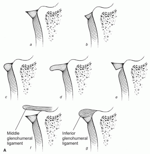 Figure 9.36 Normal variations in the glenoid labrum. A: Illustrations of variations in the anterior labrum at the midglenoid level. a, triangular; b, small but triangular; c, rounded; d, crescentic; e, recess between the labrum and cartilage; f, middle glenohumeral ligament proximal to the labrum; g, small anterior labrum with adjacent thick middle glenohumeral ligament. B: MR arthrogram demonstrating triangular (arrows) anterior and posterior labra. The posterior capsule is distended with a type II or III attachment (open arrow). C: MR arthrogram demonstrating near-complete absence of the anterior labrum (arrow) and a rounded posterior labrum (bracket). D: MR arthrogram depicting rounded anterior and posterior labra. E: MR arthrogram demonstrating a rounded posterior labrum and intermediate signal intensity and deformity of the anterior labrum (arrow) due to a prior Bankart repair. |
glenohumeral ligament. When the superior ligament is thicker, the middle glenohumeral ligament may be absent or thinner.12,37,100 The superior glenohumeral ligament may be absent in up to 10% of patients.37
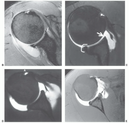 Figure 9.36 (continued) |
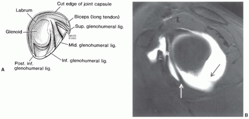 Figure 9.37 A: Illustration of glenohumeral ligaments, labrum, and capsule seen in the sagittal plane. B: Sagittal MR arthrogram demonstrating the middle glenohumeral ligament (*), the anterior band of the inferior glenohumeral ligament (white arrow), and the posterior band of the inferior glenohumeral ligament (black arrow). |
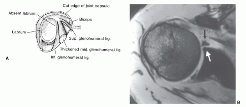 Figure 9.38 A: Illustration of the Buford complex with absent anterior superior labrum and thickening of the middle glenohumeral ligament. B: Axial MR image demonstrating an absent anterior labrum (white arrow) and thickening of the middle glenohumeral ligament (black arrow). |
inflammation or communication with the joint via a rotator cuff tear or capsular defect (Figs. 9.19 and 9.40A).12,36,61
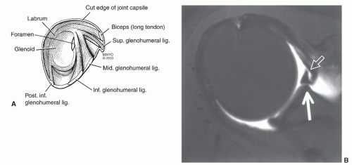 Figure 9.39 A: Illustration of the anterior labral foramen. B: MR arthrogram demonstrating a sublabral foramen with a small focal area of the anterior labrum (open arrow) that is not adherent to the underlying anterior superior glenoid (white arrow). |
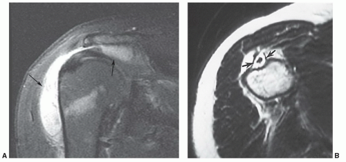 Figure 9.40 A: Coronal T2-weighted image demonstrating bursitis with distention of the subacromial-subdeltoid bursa (arrows). The rotator cuff is intact. B: Axial T2-weighted image demonstrating fluid completely surrounding the biceps tendon with distention of the tendon sheath (arrows). |
injections. Fluid typically remains up to 48 hours after an injection.81,108
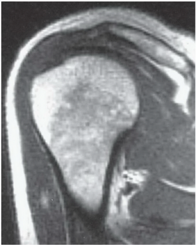 Figure 9.41 Coronal proton density image demonstrating yellow marrow in the epiphysis with mixed red and yellow marrow (predominantly red) in the metaphysis in a 19-year-old male. The marrow pattern in the clavicle is also mixed. |
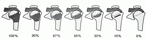 Figure 9.42 Grading system for conversion from red (100% left) to yellow marrow with no residual red marrow in grade 7. (From Richardson ML, Patten RM. Age-related changes in marrow distribution in the shoulder: MR image findings. Radiology. 1994;192:209-215.) |
rotator cuff, labrum, fluid changes, and marrow changes are most frequently discussed in the literature as noted above. Other variants, such as tendon attachments (Fig. 9.35A), can be confused with osteophytes.86 Confusion can be avoided by comparing MR findings with radiographic features. Other findings such as soft tissue calcifications (Fig. 9.47) provide additional value for radiographic comparison when interpreting MR images.
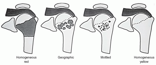 Figure 9.43 Illustration of marrow pattern categories progressing from homogeneous red to homogeneous yellow. (From Richardson ML, Patten RM. Age-related changes in marrow distribution in the shoulder: MR image findings. Radiology. 1994;192:209-215.) |
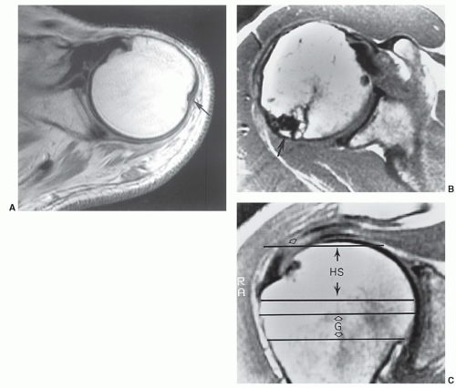 Figure 9.44 Axial SE 450/15 image of the proximal humerus (A) demonstrating the normal posterolateral groove (arrow). Axial (B) and coronal (C) proton density images demonstrating a Hill-Sachs lesion (arrow) and a rotator cuff tear (open arrow). The levels of the usual Hill-Sachs (HS) lesion and normal groove (G) are indicated with transverse lines to show where they would be seen on axial images. |
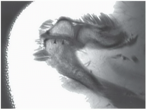 Figure 9.45 Axial proton density image shows an os acromiale (arrowheads). |
coracoclavicular sprain. Stress radiographs demonstrate subluxation of the joint. MR images demonstrate increased signal in the AC ligaments and marrow edema in the acromion and clavicle. There may also be increased signal intensity in the coracoclavicular ligament.135 Axial and sagittal image planes are most useful. Type III injuries result in disruption of the AC and coracoclavicular ligaments. The joint dislocates radiographically. MR images demonstrate increased signal intensity in both ligament complexes (Table 9.4) and widening with varying degrees of joint subluxation or dislocation.135,143 The deltoid and trapezius muscles may be detached from the distal clavicle.135 All three image planes maybe required toassess the soft tissue and articular changes completely. A fracture at the base of coracoid has also been reported instead of coracoclavicular ligament disruption.143 Fractures of the coracoid base are most obvious on sagittal images. Type IV dislocations result in posterior displacement of the clavicle which is most easily appreciated on axial
images.135 Sternoclavicular dislocations may also occurwith this injury. Therefore, both medial and lateral ends of the clavicle should be imaged.135,143 Type IV dislocations are similar to type III except the trapezius and deltoid muscles are stripped from the ends of the clavicle and acromion. The clavicle is significantly elevated by cephalad traction of the sternocleidomastoid muscle. This feature is best appreciated on coronal images. Type VI dislocations result from severe force from superior to the clavicle with the humerus abducted.143 Type IV injuries may be most easily identified on coronal or sagittal images.
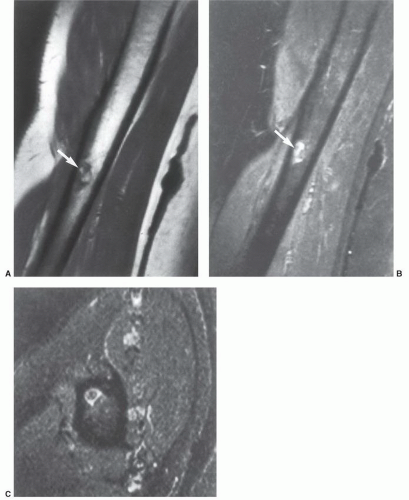 Figure 9.46 Pseudotumor deltoideus. A: Coronal T1-weighted image of the right humerus shows an area of fat signal intensity surrounded by low signal intensity (arrow) at the deltoid insertion. Inversion recovery coronal (B) and axial (C) images show low to intermediate signal intensity surrounded by high signal intensity (arrow). (From Morgan H, Damron T, Cohen H, et al. Pseudotumor deltoideus. A previously undescribed variant at the deltoid insertion site. Skeletal Radiol. 2001;30:512-518.) |
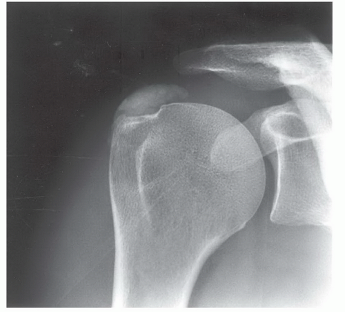 Figure 9.47 Anteroposterior radiograph demonstrates dense calcification in the supraspinatus tendon. |
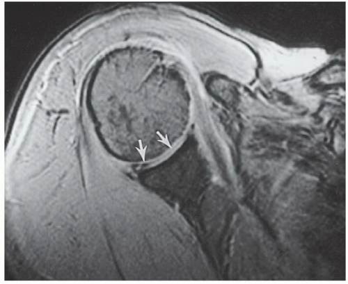 Figure 9.48 Axial gradient-echo image of the shoulder with linear and globular areas of intra-articular decreased signal intensity (arrows) due to vacuum phenomenon. Joint fluid would be high signal intensity. Loose bodies tend to be located in recesses or areas of articular abnormality. |
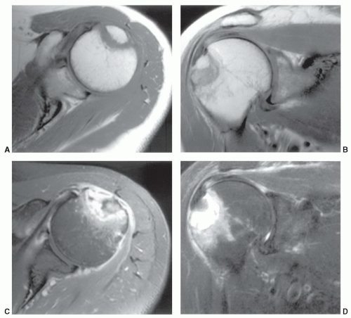 Figure 9.49 Patient with posttraumatic shoulder pain. Routine radiographs were normal. Axial (A) and coronal (B) T1-weighted and axial (C) and coronal (D) fast spin-echo T2-weighted images demonstrate a fracture of the greater tuberosity with fluid between the fragments on the T2-weighted images C and D. |
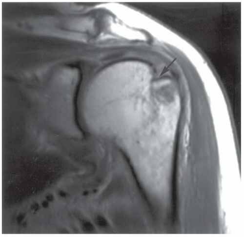 Figure 9.50 Coronal proton density-weighted image demonstrating a Hill-Sachs lesion (arrow) not evident on routine radiographs. |
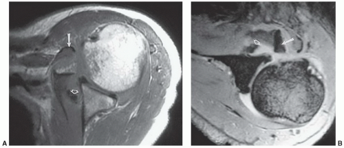 Figure 9.51 Lesser tuberosity avulsion and tears in the capsule and middle glenohumeral ligament. Axial proton density (A) and gradient-echo (B) images show the displaced lesser tuberosity (arrow) and ligament tear (open arrow). |
positive clinical examination. Other changes did not correlate with clinical findings.116 Schweitzer et al.148 reported joint effusions in 66% of patients with grade 2 or 3 impingement compared with 12% in normal volunteers.
Table 9.4 Acromioclavicular Joint Injuries | ||||||||||||||||||||||||
|---|---|---|---|---|---|---|---|---|---|---|---|---|---|---|---|---|---|---|---|---|---|---|---|---|
| ||||||||||||||||||||||||
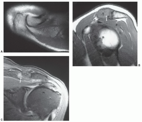 Figure 9.52 Posttraumatic osteolysis. A: Axial T1-weighted image of the normal acromioclavicular joint. The bone margins are sharp and there is no joint effusion or soft tissue edema. Proton density coronal (B) and T2-weighted sagittal (C) images demonstrate irregularity and abnormal signal in the distal clavicle (arrow) with sparing of the acromion. |
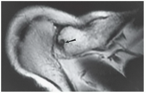 Figure 9.53 Axial T1-weighted image shows residual erosive changes (arrow) in the distal clavicle after traumatic osteolysis. |
 Figure 9.54 Chronic untreated traumatic osteolysis with marked joint hypertrophy on this sagittal T1-weighted image. |
Table 9.5 Etiologies of Rotator Cuff Tears | |||||||||||||||||
|---|---|---|---|---|---|---|---|---|---|---|---|---|---|---|---|---|---|
|
impingement, etc.) and primary cuff degeneration, which may be ischemic.
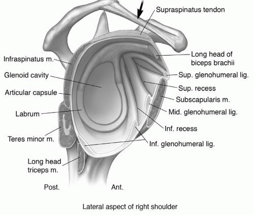 Figure 9.55 Illustration demonstrating the coracoacromial arch and supporting structures of the shoulder. Note the coracoacromial ligament (arrow). |
has also been implicated in impingement (Fig. 9.57) and rotator cuff tears.115,168,178,179 A type 1 acromial configuration is straight; type 2, curved; type 3, hooked; and type 4 has a convex inferior surface (Fig. 9.57).21,31 Anterior or lateral angulation of the acromion may also cause impingement (Fig. 9.58).178,186 Type 1 acromions occur in 18% to 23%; type 2 in 42% to 68%; and type 3 10% to 39% of patients. Type 4 acromia occur in 7% of the general population.12,16,179 Type 3 or hooked acromia are more common in males.180 Zlatkin and Falchook reported rotator cuff tears in 51% of patients with type 3 acromia, os acromiale, or anterior inferior acromial bone spurs (Fig. 9.59). More recent studies noted type 3 acromia in 70% to 80% of rotator cuff tears. Only 3% of patients with rotator cuff tears had type 1 acromia.181
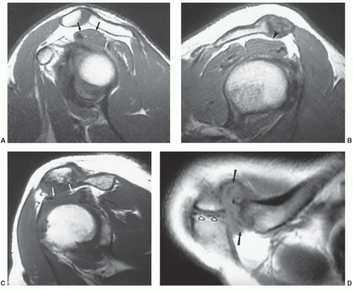 Figure 9.56 Impingement of the rotator cuff. A: Sagittal T1-weighted image of a normal acromioclavicular joint region. There is fat between the bone and the upper surface (arrows) of the supraspinatus is convex. B: Sagittal T1-weighted image demonstrating degenerative change in the acromioclavicular joint causing mild impingement with a concave upper surface (arrowhead) on the supraspinatus muscle. There is still fat between the muscle and joint. C: Sagittal T1-weighted image demonstrating moderate to marked impingement due to AC joint hypertrophy (arrows). D: Axial proton density-weighted image demonstrating acromioclavicular joint degeneration (arrows) and an os acromiale (open arrows). |
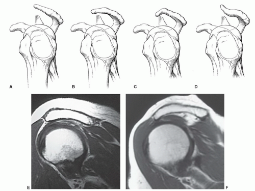 Figure 9.57 Illustrations of acromial shapes and orientations as seen on oblique sagittal MR images. A: Flat. B: Curved. C: Hooked. D: Convex inferior surface. E: Sagittal T1-weighted image of a curved (type 2) acromion. F: Sagittal T1-weighted image of a curved, anteriorly angled acromion compressing the supraspinatus. |
Related posts:

Stay updated, free articles. Join our Telegram channel

Full access? Get Clinical Tree


