Fig. 1
(a) Plain radiographs are based on a point-shaped x-ray source and a conical projection. Therefore, distortion of the anatomy is unavoidable. Typically, the more anterior an object is located to the x-ray source (anterior rim in blue), the more lateral it is projected. (b) Computer tomography and magnetic resonance imaging are based on parallel rays and, therefore, these imaging modalities do not result in distortion (Reprinted with permission)
Film-Tube Distance
The film-tube distance affects the anatomy of the hip on the radiograph, e.g., the acetabular orientation. With increasing film-tube distance, the apparent acetabular anteversion increases. In contrast, with decreasing film-tube distance, the anteversion decreases and the acetabulum may appear retroverted (Fig. 2).
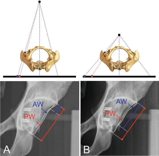
Fig. 2
The anatomy of the hip on a plain radiograph depends on the film-tube distance. (a) With a regular film-tube distance, a cranial retroversion exists indicated by a crossing of the anterior wall (AW) and posterior acetabular wall (PW). (b) By decreasing the film-tube distance, the apparent retroversion becomes more pronounced indicated by a more distal crossing of the AW and PW (Reprinted with permission)
Patient-Film Distance
The patient-film distance has only a minor influence on the transformation of the hip on the radiograph [1]. The patient-film distance usually remains consistent for an individual patient. Interindividual differences exist in patient-film distance. But even in very obese patients, the distance between hip joints and the table shows minor variation since the increased body volume mainly affects the anterior part of the body (Fig. 3).
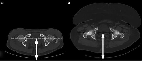
Fig. 3
The patient-film distance has a minor effect on the anatomy of the hip on the radiograph. (a) The patient-film distance shows a minor increase even in (b) obese patients since the increased body volume mainly affects the anterior part of the body
Centering and Direction of the X-Ray Beam
The centering of the x-ray beam is one of the most important factors influencing the anatomy of the hip on plain radiographs [1]. On a standard anteroposterior (AP) pelvic radiograph, the central beam is directed to the midpoint between the upper border of the symphysis and a line connecting both anterior superior iliac spines (Fig. 4). By lowering the center of the x-ray beam (low-centered AP pelvic radiograph), the apparent acetabular anteversion increases (Fig. 5). The acetabular anteversion also increases by moving the central beam from the center of the pelvis to the center of the hip (Fig. 6). Since the radiographic parameters to describe the morphology of the hip have been defined on pelvis-centered radiographs, it is not recommended to use low-centered or hip-centered radiographs for joint-preserving surgery.
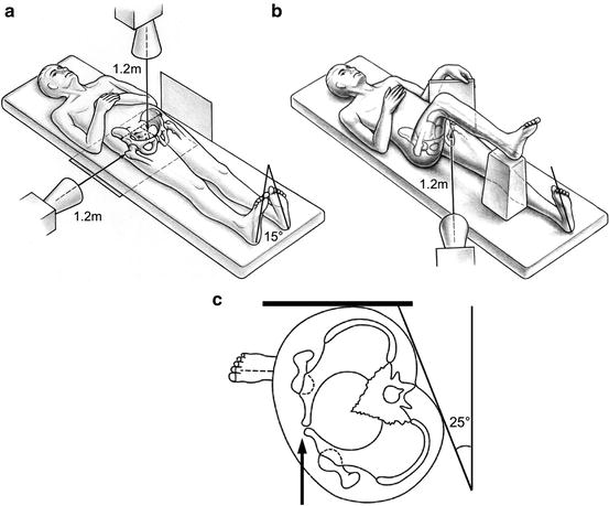
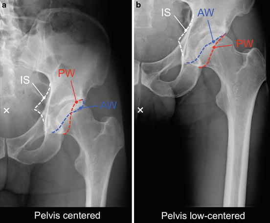
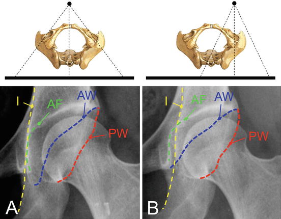
Fig. 4
Acquisition techniques for the different hip projections. (a) The anteroposterior (AP) pelvis radiograph is acquired with the patient supine, the legs 15° internally rotated to compensate for femoral antetorsion, and the x-ray beam centered to the midpoint between the upper part of the symphysis and a line connecting the anterior superior iliac spines. A concomitant true lateral view can be performed to evaluate pelvic tilt. The (b) cross-table axial view is performed with the patient supine, the x-ray beam angled in a 45° angle, and centered to the inguinal fold. The (c) false profile view is performed with the patient supine, with the contralateral hip tilted backward by 25°, and with the axis of the ipsilateral foot parallel to the film
Fig. 5
Centering of the x-ray beam directly influences the anatomy of the hip on a plain radiograph, e.g., acetabular anteversion. (a) On the pelvis-centered radiograph (white cross represents central beam), the acetabulum is retroverted indicated by a crossing of the anterior (AW) and posterior acetabular wall (PW) and a positive ischial spine sign [ischial spine (IS) projected medially to the pelvic brim]. (b) On the low-centered radiograph, the crossover and the ischial spine signs are negative, and therefore, an acetabular retroversion would have been missed
Fig. 6
The anatomy of the hip on a plain radiograph directly depends on the centering of the x-ray. When moving the center of the x-ray from (a) the center of the pelvis to the (b) center of the hip, the acetabulum becomes more anteverted indicated by a more distant course of the anterior (AW) and posterior acetabular wall (PW). In addition, the acetabulum appears deeper with a positive coxa profunda sign [acetabular fossa (AF) crossing the ilioischial line (I)]
Standard pelvic radiographs are performed with an AP direction of the x-ray beam. In contrast, chest radiographs are performed with a posteroanterior direction of the x-ray beam. Objects closer to the source of the x-rays (e.g., symphysis in AP direction) become magnified compared to those more distant (e.g., sacrum in AP direction). Since the hip is located in the middle of the pelvis, the direction of the x-ray beam has a minor effect on the projected anatomy on the plain radiograph.
Pelvic Orientation
The spatial orientation of the pelvis during radiograph acquisition can vary considerably which directly affects the projected morphology of the hip on the radiograph (Fig. 7). The orientation of the pelvis can vary in three dimensions: obliqueness, rotation, and tilt. While variations in pelvic obliqueness and rotation can be decreased by a standardized acquisition technique, pelvic tilt can vary substantially. An interindividual range of pelvic tilt up to 60° has been reported [2]. Pelvic tilt mainly affects the apparent anteversion of the acetabulum (Fig. 7).
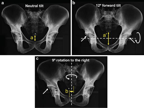
Fig. 7
Pelvic orientation during radiograph acquisition affects the projected anatomy of the hip. (a) A cadaver pelvis with metal-wire-marked acetabular walls is mounted in a holding device in neutral position. Both acetabula are anteverted. Pelvic tilt during radiograph acquisition is estimated by the vertical distance between sacrococcygeal joint and symphysis (distance a). (b) By a 12° forward tilt of the pelvis, both acetabula show a cranial retroversion (positive crossover signs indicated by arrows). The increased pelvic tilt is reflected by the increased distance a′. (C) A rotation of 9° towards the right side results in a cranial retroversion of the right acetabulum and an increased anteversion on the left side. Pelvic rotation is estimated by the horizontal distance b. Ideally, the distance b is 0 cm
An error due to pelvic obliqueness can simply be corrected by measuring the radiographic parameters according to an anatomical horizontal reference, e.g., the teardrop line. Pelvic rotation can be determined by the horizontal distance between the center of the sacrococcygeal joint and the center of the symphysis (Fig. 7). Ideally, these anatomical landmarks are in line (Fig. 7). Rotation to the right (left) side results in decreased (increased) acetabular anteversion on the right (left) side (Fig. 7). Pelvic tilt can be estimated by the vertical distance between the sacrococcygeal joint and the upper border of the symphysis (Fig. 7). In average this vertical distance is 47 mm in men and 32 mm in women [3]. However, to accurately determine pelvic tilt, a onetime true lateral pelvic view is needed [3]. With increasing pelvic tilt, the apparent acetabular anteversion decreases and vice versa (Fig. 7).
Fluoroscopy
Fluoroscopy differs in terms of acquisition technique compared to a regular AP pelvic view (Fig. 8). These differences have to be respected when interpreting fluoroscopic images. First, in fluoroscopy the x-ray beam is in posteroanterior direction instead of AP direction in a standard pelvic view. Next, the central beam is centered over the hip, and not the pelvis. Additionally, the tube-intensifier distance is decreased. This results in a more anteverted-appearing acetabulum on fluoroscopic images compared to regular pelvic radiographs (Fig. 8).
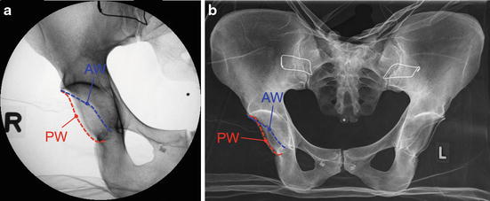
Fig. 8
(a) Fluoroscopic imaging is performed with a posteroanterior direction of the x-rays, a central beam centered over the hip, and a decreased tube-intensifier distance. This results in a more anteverted acetabular orientation. On the fluoroscopic image, the anterior and posterior acetabular walls do not cross, whereas on the (b) regular anteroposterior pelvis radiograph, there is a cranial crossover sign (arrow)
Radiographic Projections of the Hip
The standard radiographic evaluation of the hip includes two projections: the AP pelvic view and an axial view of the hip. In total hip arthroplasty, a deep-centered pelvic view or hip-centered view has been used. Due to the different centering of the x-ray beam in these views, the projected anatomy of the hip is significantly altered, and therefore, these views are not recommended in hip-preserving surgery. Different techniques have been described for the axial view of the hip including the axial cross-table, Dunn-Rippstein, Lauenstein, or frog-leg lateral views. In addition to the AP and axial view of the hip, additional projections exist which are performed to answer specific questions, e.g., the false profile to evaluate the anterior acetabular coverage.
Anteroposterior (AP) Pelvis View
Basic radiographic evaluation of the hip is performed with an AP pelvis view (Table 1). It gives a good visualization of the overall morphology of the pelvis and the proximal femur. It allows a comparison of the morphology of the symptomatic hip to the contralateral side. An AP pelvis view can be performed supine or standing. We favor pelvis radiographs performed in supine position because they can directly be compared to pelvic radiographs performed intraoperatively or at follow-up during early rehabilitation and restricted weight bearing. The legs are 15° internally rotated to compensate for femoral antetorsion (Fig. 4). The film-focus distance is 120 cm. The central beam is centered to the midpoint between the upper border of the symphysis and a line connecting the two anterior superior iliac spines.
Table 1
Radiographic projections of the hip
Projection | Technique | Features |
|---|---|---|
Anteroposterior (AP) pelvis | Patient supine or standing, legs 15° internally rotated, centering of x-ray beam to the midpoint between the upper border of symphysis and a line connecting both ASIS | Basic radiographic evaluation of the hip for hip-preserving surgery, total hip arthroplasty, or trauma surgery |
Deep-centered pelvis | Patient supine or standing, legs 15° internally rotated, centering of the x-ray beam below the symphysis | Performed in total hip arthroplasty; not recommended for hip-preserving surgery due to different x-ray centering and altered morphology of the hip |
Anteroposterior (AP) hip | Patient supine or standing, legs 15° internally rotated, hip-centered x-ray beam | Performed in total hip arthroplasty; not recommended for hip-preserving surgery due to different x-ray centering and altered morphology of the hip |
Axial cross-table | Patient supine, ipsilateral leg 15° internally rotated, contralateral hip flex and elevated | Anterior and posterior femoral head-neck contour |
Dunn-Rippstein | Patient supine, hips in 90° flexion and 20° abduction, knees in 90° of flexion, legs in holding device | Femoral antetorsion, anterior and posterior femoral head-neck contour |
Modified Dunn | Patient supine, hips in 45° flexion and maximal abduction | Increased sensitivity to detect cam deformities in the anterosuperior head-neck area |
Lauenstein | Patient supine, hip centered x-ray beam, hip and knee flexed, and hip in abduction | Anterior and posterior femoral head-neck contour |
Frog-leg lateral | Patient supine, pelvis-centered x-ray beam, both hips and knee flexed, and the leg abducted so the soles of the feet contact | Anterior and posterior femoral head-neck contour |
False profile | Patient standing, hip-centered x-ray beam, contralateral hip is tilted backward by 25°, ipsilateral foot remains parallel to radiographic table | Anterior acetabular coverage, anterosuperior subluxation, quantification of posteroinferior joint space |
True lateral | Patient supine, horizontal x-ray beam from lateral and centered to the hip | Pelvic inclination; concomitantly performed with AP pelvis view to correlate pelvic inclination with vertical distance from symphysis to sacrococcygeal joint on AP pelvis view |
Functional (abduction/adduction) | Patient positioning and centering of x-ray for AP pelvis view; additional abduction or adduction of the hip, possible combination of abduction, internal rotation and flexion | Abduction view to differentiate between subluxation and true joint space narrowing in dysplastic hips, to simulate acetabular coverage following acetabular reorientation or femoral osteotomy |
Low-Centered Pelvis View
In total hip arthroplasty, low-centered pelvis views are performed to ensure that both cup and stem are entirely shown (Table 1). Due to different centering of the x-ray beam and its effect on the projected anatomy of the hip, low-centered pelvis views are not recommended for hip-preserving surgery (Fig. 5).
Anteroposterior (AP) Hip View
For the AP hip view, the central beam is centered to the hip (Table 1). Hip-centered views are mainly performed for total hip arthroplasty. The different centering of the x-ray results in an altered projection of the hip, and therefore, this view is not recommended for hip-preserving surgery (Fig. 6). On hip-centered radiographs, it is impossible to define the anatomical horizontal reference because of the missing contralateral landmark (e.g., teardrop figure). This makes the measurement of anatomical referenced cup inclination on hip-centered radiographs impossible. In addition to an AP pelvis view, a hip-centered view can be used to differentiate whether a cup is anteverted or retroverted. While anteversion increases for an anteverted cup on a hip-centered view (Fig. 6), anteversion decreases for a retroverted cup on a hip-centered view compared to a pelvis-centered radiograph [4].
Axial Cross-Table View
The axial cross-table view allows evaluating the anterior and posterior contour of the femoral head-neck junction (Fig. 9). This view is performed with the patient supine and the ipsilateral leg 15° internally rotated to compensate for femoral antetorsion (Fig. 4). The contralateral hip is flexed and the leg elevated (Fig. 4). The lateral x-ray beam is angled in a 45° angle and centered to the inguinal fold (Table 1).
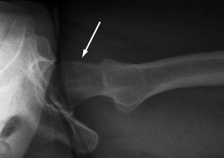
Fig. 9
The axial cross-table view allows evaluating the anterior and posterior contour of the femoral head-neck junction. In hips with cam-type femoroacetabular impingement (FAI), the head-neck contour is aspherical (arrow)
Dunn-Rippstein View and Modified Dunn View
The Dunn-Rippstein view is performed with the patient supine (Table 1) [5, 6]. Both hips and knees are 90° flexed, and the legs are hold on a special holding device in 20° abduction. This hip view was originally introduced to measure exact femoral antetorsion [5, 6]. However, compared to CT-based measurements, this method is not free of error due to patient malpositioning [7]. The Dunn-Rippstein view can be used as an alternative to the axial cross-table view to evaluate the anterior and posterior contour of the femoral head-neck junction. Femoral head-neck asphericities in hips with FAI are most often localized in the anterosuperior region [8]. These asphericities are best shown with a “modified Dunn view” with the hips in 45° of flexion [9].
Lauenstein and Frog-Leg Lateral View
Both the Lauenstein [10] and frog-leg lateral views are performed with the patient supine (Table 1). The Lauenstein view is performed with the hip and knee flexed and the hip in abduction. The central beam is centered to the hip. If abduction of the hip is impaired, the pelvis can be tilted to the ipsilateral side. The frog-leg lateral view is taken with both hips and knee flexed and the leg abducted so the soles of the feet contact. Both views are used as an alternative to the axial cross-table view to evaluate the anterior and posterior contour of the femoral head-neck junction.
False Profile of Lequesne and de Sèze
The false profile view is performed with the patient standing (Table 1). The ipsilateral hip touches the radiographic table (Fig. 4). The contralateral hip is tilted backward by 25°. The axis of the ipsilateral foot remains parallel to the film. The false profile view is performed to evaluate the anterior acetabular coverage or anterosuperior subluxation of the femoral head which is of particular interest in dysplastic hips (Fig. 10). In addition, the false profile view allows to quantify the posteroinferior joint space (Fig. 10).
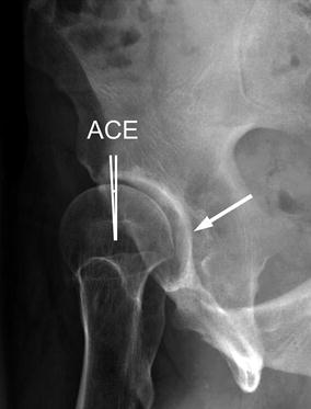
Fig. 10
A false profile view is performed to evaluate the anterior acetabular coverage by anterior center-edge (ACE) angle. In this patient with hip dysplasia, the anterior acetabular coverage is clearly deficient (ACE angle less than 25°). In addition, the false profile view allows to judge the posteroinferior joint space. Typically, dysplastic hips have a subluxation of the femoral head with an irregular joint space and widening of the posteroinferior joint space (arrow)
True Lateral Pelvis View
A true lateral pelvis radiograph can be performed to assess the pelvic tilt (Table 1). This view is acquired in the supine position and in addition to an AP pelvis view (Fig. 4). The pelvic tilt angle is constructed as the angle between a horizontal line and a line connecting the upper border of the symphysis and the sacral promontory (Fig. 11). Neutral tilt is defined as an angle of 60° [3, 11]. A linear correlation exists between the tilt angle (Fig. 11) and the vertical distance between the upper border of the symphysis and the sacrococcygeal joint on the AP pelvis radiograph (Fig. 7) [3]. Therefore, a true lateral view is only performed once for an individual patient. Exact tilt can be calculated from any other AP pelvis view using the linear correlation and the onetime determination of pelvic tilt on the true lateral view [3].
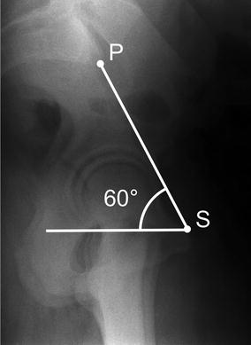
Fig. 11
 Neuromuscular Hip Disorders: Focus on Cerebral Palsy
 Femoral Deformities: Varus, Valgus, Retroversion, and Anteversion
 Surgical Technique: Arthroscopic Labral Management
 Surgical Technique: Endoscopic Gluteus Medius Repair
 Introduction to Static and Dynamic Overload of Hip Pathology
 Atraumatic Instability and Surgical Technique


On a true lateral pelvis radiograph, the pelvic tilt angle is constructed by a line connecting the sacral promontory (P) and the upper border of the symphysis (S) and a horizontal line. A pelvic tilt of 60° is defined as neutral position
Related posts:
Neuromuscular Hip Disorders: Focus on Cerebral Palsy
Femoral Deformities: Varus, Valgus, Retroversion, and Anteversion
Surgical Technique: Arthroscopic Labral Management
Surgical Technique: Endoscopic Gluteus Medius Repair
Introduction to Static and Dynamic Overload of Hip Pathology
Atraumatic Instability and Surgical Technique
Stay updated, free articles. Join our Telegram channel
Full access? Get Clinical Tree
