Fig. 1
Varus derotation intertrochanteric osteotomy. The patient is a 28-year-old female with left hip pain for over 2 years. The left leg is 1.5 cm long. The left leg has an in-toeing gait. There is borderline hip dysplasia with the center-edge angle 20° on the AP view and 23° on the false-profile view. Coxa valga is present with a neck-shaft angle of 140°. In addition, there is excessive femoral anteversion of 34° along with increased acetabular anteversion of 27°. A femoral neck cam lesion, with an alpha angle of 64°, is also present. A varus derotation intertrochanteric osteotomy was performed along with a concomitant hip arthroscopy and femoral neck osteochondroplasty to avoid further impingement after diminishing femoral anteversion. It was felt that a femoral intertrochanteric osteotomy would best correct the various deformities and reduce cartilage overload. A 13° varus correction was performed along with a 20° reduction of the femoral anteversion. (a) AP pelvis radiograph. (b) Dunn view lateral left hip showing cam lesion. (c) Preoperative plan tracing for a VRO with a 90° blade plate. (d) Arthroscopic femoral neck osteochondroplasty performed immediately prior to the osteotomy. (e) Steinmann pin placement at the osteotomy site and into the femoral neck at the desired angle of varus correction. (f) Chisel insertion hugging the proximal Steinmann pin, location confirmation should be made on both the AP and lateral views. (g) Lamina spreader used to open the osteotomy and mobilize the fragments. Rotation control Steinmann pins have been placed on either side prior to performing the osteotomy. (h) AP radiograph at follow-up. (i) Lateral radiograph at follow-up. The operation not only provided pain relief but also restored normal hip rotation and foot-progression angle, prevented hip impingement, and equalized leg lengths
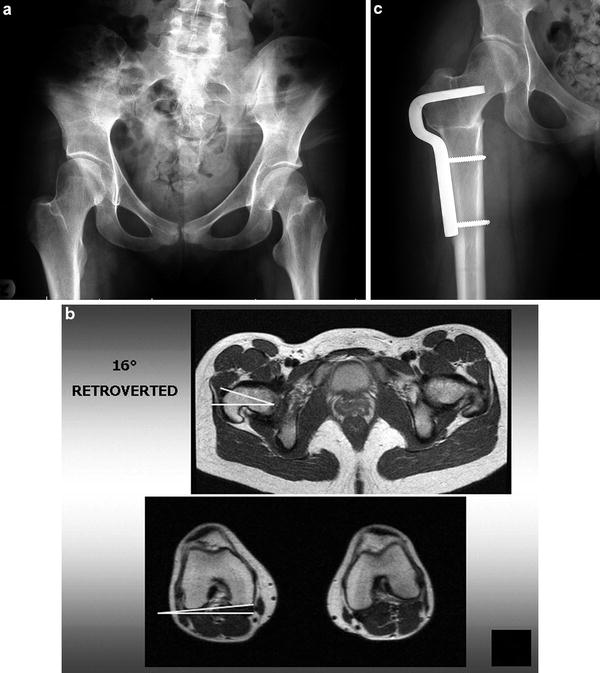
Fig. 2
Varus derotation intertrochanteric osteotomy with femoral retroversion. The patient is a 19-year-old female who was born with a dislocated right hip. She was treated with an open reduction and bracing in infancy. Pain in the hip has been present for over 1 year, limiting activities. The right leg is 1.5 cm longer than normal. She has limited internal rotation, a positive impingement test, excessive external rotation, and minimal internal rotation. There is coxa valga with a neck-shaft angle of 146°, borderline acetabular dysplasia, and 16° of femoral retroversion. A varus derotation intertrochanteric osteotomy was performed to correct valgus and retroversion of the femur. (a) Preoperative AP pelvis radiograph. (b) Axial MRI images through the hip and knee demonstrating 16° of retroversion of the right femur. The left hip has normal femoral anteversion. (c) Postoperative AP radiograph of the right hip. The osteotomy has relieved pain, corrected the foot-progression angle, and restored normal hip range of motion and leg lengths
All appropriate radiographic studies should be performed. High-resolution MRI scans are needed to assess the degree of intra-articular damage. While it is possible to open the hip joint during a VRO, it makes for a more extensive dissection and it may still be very difficult to get an excellent view of intra-articular pathology. It is usually preferable to perform hip arthroscopy instead to address the intra-articular problems, either staged or simultaneously immediately before the osteotomy. Plain radiographs should include an AP pelvis, Dunn view lateral, and a false-profile view of the involved hip. In addition, “functional” radiographs should be obtained to simulate the osteotomy. For a varus osteotomy, the AP view with legs abducted will simulate how the coverage will appear after adding varus; if there is excessive anteversion, the leg should also be internally rotated with the abduction to simulate the derotation component of the VRO.
A 3-D CT scan will provide excellent visualization of the deformity and is the most accurate method to measure acetabular and femoral version. Preoperative templating and planning should not be omitted. The surgeon can think through the steps involved, decide on the degree of angular correction, select the correct blade plate, and predict the degree of shortening or lengthening. It is also possible to predict the length of the blade and where it will come to rest in the femoral head.
The operation should be performed on a radiolucent table. Either the supine or lateral position may be used. In the supine position, a radiolucent bump or float beneath the involved buttock makes the exposure easier.
A straight lateral incision is used. A larger incision may be required if the articulated tensioning device is to be used distally to compress the osteotomy site. The vastus lateralis is elevated from the femur near the linea aspera. Perforating vessels are identified and coagulated. It is helpful to angle the fascia incision anteriorly just distal to the vastus ridge, this will keep adequate tissue at the vastus lateralis origin to permit a complete closure of the vastus fascia over the blade plate. The vastus origin is then elevated proximally to allow the plate to be fully opposed to the femoral cortex.
Two smooth Steinmann pins are placed, each approximately 7/64 or 1/8 in. One is placed transversely from lateral to medial at the superior border of the lesser trochanter at the proposed site of the osteotomy. The second is placed just proximal to the proposed path of the chisel. The proximal pin has to be placed at such an angle (usually 105–110° to the shaft) so that the chisel that hugs the pin will make the correct path for the blade plate. It is helpful to use the various metal triangles in the Synthes blade plate set to achieve the correct angle in the coronal plane. Care must be taken to confirm that the pin is properly seated in the lateral projection as well. If there is excessive external rotation at 90°, a frog-type view may show the lateral projection. If the patient has excessive anteversion, then it may be easier to fully internally rotate and cant the fluoroscope over the involved hip to achieve the lateral view. Placing the chisel is the most crucial part of the operation. After placing the pin, compare it to the preoperative tracing. Are the two comparable? It is not necessary to be concerned with rotational control at this point. The chisel should be inserted at the correct angle on the AP projection so that once the femur is sectioned and the 90° blade plate inserted, it will affect the correct coronal plane correction. The chisel should hug the Steinmann pin; this will assure not only the correct varus/valgus angle but also the correct anterior/posterior placement in the femoral head and neck (provided that this was controlled fluoroscopically with the pin).
The 90° adult blade plate has blade lengths of 40, 50, 60, and 70 mm. One should have an idea of the correct length from the preoperative planning. The offsets available are 10, 15, or 20 mm. Again, preoperative tracing will help to determine which angled plate should fit the contour of the femur best after correction. The blade plate was designed with this offset to cause an intentional medial displacement of the femoral shaft so as not to overload the medial compartment of the knee.
There should be at least 15 mm from the osteotomy to the site of chisel insertion. Any less than this may cause the blade to break into the osteotomy site when compression is applied.
The harder the bone, the more important it is to extract the chisel partially after each advancement of approximately 1 cm. If the chisel is inserted to the complete 40–70 mm in one thrust, it may be extremely difficult to extract the chisel.
Before inserting the chisel, determine whether flexion or extension will be needed. If neither is desired, then the handle of the chisel guide should be parallel to the shaft of the femur during insertion. If 10–30° of flexion or extension are desired (as in cases of SCFE or AVN of the femoral head), this must also be taken into account before inserting the chisel. Flexion osteotomies have the effect of rotating the femoral head anteriorly, vice versa for an extension osteotomy. During insertion, periodic AP and lateral fluoroscopic images should be taken to make sure the chisel is following a path closely applied to the Steinmann pin. To control rotation, Steinmann pins are placed anteriorly both proximal and distal to the osteotomy site. The pins must be placed at the desired angle of correction. It is usually easier to set the pins at the desired degree of correction (i.e., 20° apart from each other; the triangles are used to determine this) so that making them parallel to each other during blade plate fixation will have affected the desired rotational correction. Only then can the transverse osteotomy be performed, otherwise there is no control of rotation. The osteotomy is made parallel to the previously placed Steinmann pin at the superior border of the lesser trochanter.
After performing the osteotomy of the femur, a lamina spreader helps to mobilize the fragments sufficiently. If it is not in the way, the chisel can be kept in the proximal fragment until this moment to visualize the correct path for blade plate insertion. The proximal Steinmann pin will help to ensure the correct path as well. The blade plate is then inserted and impacted with the pencil punch until the plate comes to rest against the lateral cortex of the proximal fragment. The distal fragment is brought to rest against the plate and secured with a Verbrugge clamp. Prior to tightening the clamp, the distal femur is rotated to align the rotation control pins parallel to each other.
The articulated tensioning device helps to compress the osteotomy site. Historically, a medial wedge of bone was removed to achieve a greater surface area of bony apposition. However, this tends to shorten the femur needlessly. Instead, a single transverse osteotomy is made. With compression, the medial cortex of the proximal fragment is impacted into the canal of the distal fragment, due to the intentional medial displacement. An incision approximately 5 cm longer may be required to use the articulated tensioning device that attaches to the distal screw hole. Alternatively, compression can be achieved by placing the plate screws in compression mode.
With harder bone, it may not be necessary to fill all four screw holes on the plate. The proximal screw just below the blade at the corner of the blade plate should be used if there is any compromise of bone quality.
At this point, the AP and lateral fluoroscopic images should be inspected. Is the osteotomy well opposed and well aligned? Does it compare favorably with the preoperative plan tracing? Are all the screws in optimal position?
The hip range of motion should now be tested after removing the Steinmann pins and tensioning device. At 90° of flexion, there should now be internal rotation if correcting retroversion and improved external rotation if excessive anteversion was corrected.
If it is felt that excessive varus was required to correct the neck-shaft angle, the greater trochanter tip may be too high compared to the level of the center of rotation. A greater trochanteric advancement may be done as well. The chisel is inserted into the greater trochanter at a 90° angle (the position it will be and when the blade plate was inserted). It is inserted initially only to the depth of the greater trochanter osteotomy. The trochanter osteotomy is performed and then the Steinmann pin and chisel inserted as needed to correct the neck-shaft angle.
After the osteotomy, the blade can be inserted first into the greater trochanter, which is then advanced distally before finishing the blade insertion into the head/neck fragment. This initial insertion into the greater trochanter has also to consider flexion/extension corrections. It may be desirable to augment the greater trochanter fixation with supplemental screws.
The vastus fascia is then closed over top of the plate. Drains are used if required and the wound closed in layers. Postoperatively, the patient can be out of bed as soon as possible. A cast or brace is not required. There are no range of motion precautions. The patient is kept at 20° toe-touch weight-bearing until 6 weeks postoperatively, at which time progression is made to full weight-bearing if bone consolidation is evident.
Valgus Intertrochanteric Osteotomy: Surgical Technique
(A representative case example is shown in Fig. 3.)
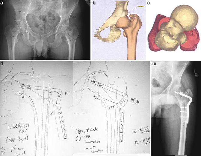
Fig. 3
Valgus derotation intertrochanteric osteotomy . The patient is a 30-year-old male who presented with several years of increasing left hip pain. In addition, he noted a pronounced lack of external hip rotation since the age of 6. The left leg is 1.5 cm shorter than the right leg. A valgus derotation intertrochanteric osteotomy was preformed. (a) AP radiograph of the pelvis demonstrating coxa vara with a neck-shaft angle of 121° with a relatively high greater trochanter. (b) 3-D CT scan image of the left hip demonstrating the excessive femoral anteversion as well as coxa vara . (c) Superimposed axial images of the proximal and distal femur demonstrate 44° of femoral anteversion. (d) Preoperative plan tracing for a valgus derotation intertrochanteric osteotomy employing a 110° blade plate. (e) Correction of the neck-shaft angle to 135°. In addition, approximately 25° of femoral anteversion was reversed. The procedure relieved pain, restored normal hip rotation and equilibrated leg lengths. Hip abductor strength also improved
The valgus osteotomy is performed in a similar fashion to the varus osteotomy, with certain differences. The valgus osteotomy tends to lengthen the leg; therefore, it may be desirable to remove a lateral-based wedge from the osteotomy site. This will not only improve bony apposition but will also help to minimize undesired leg lengthening.
If the involved leg is already short, then the lengthening effect may be desirous.
Instead of using the 90° blade plate commonly used with varus intertrochanteric osteotomy, the plates ranging from 95° to 130° are used instead. The correct plate can be determined from preoperative planning and tracing.
Care must be taken when using the higher angled plates with the articulated tensioning device. With a 90° plate, almost pure compression is generated. However, with more valgus angles, the device may have the effect of pulling the blade out of the proximal fragment. This must be monitored carefully fluoroscopically.
As opposed to the varus intertrochanteric osteotomy, some lateral displacement of the distal fragment is usually desirous to centralize the leg axis within the knee joint.
Derotation Femoral Osteotomy : Surgical Technique
(A representative case example is shown in Fig. 4.)
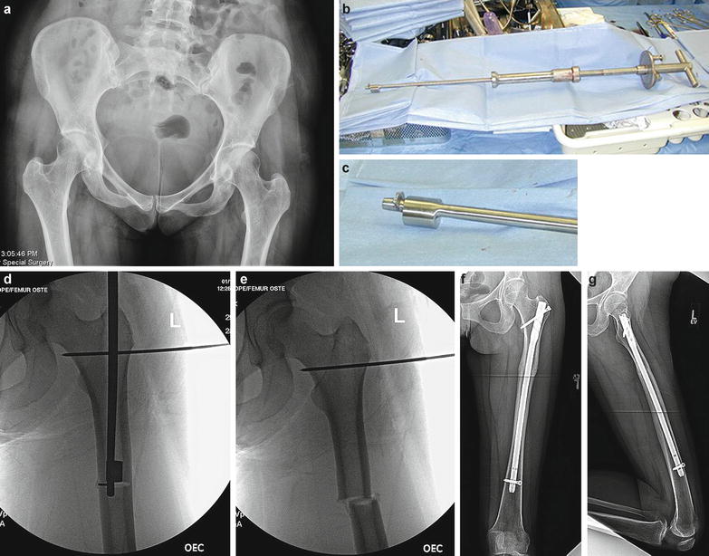
Fig. 4
Derotation osteotomy of the femoral shaft. The patient is a 28-year-old female with several years of left hip pain. She had previously undergone arthroscopy and labral debridement, which was minimally effective. The center-edge angle and neck-shaft angle are in normal range, but femoral anteversion measures 38°. A derotation subtrochanteric osteotomy was preformed. The osteotomy was performed closed with an intramedullary Winquist saw, fixation achieved with a trochanteric entry intramedullary nail. (a) AP pelvis radiograph. (b) Winquist saw. (c) Close-up of Winquist cam/blade assembly. (d) Intraoperative fluoroscopic image showing the femur nearly transected. The Steinman pin is for rotation correction control, the distal control pin (not seen in the figure) is located in the supracondylar region. (e) The femur now transected, allowing free femoral rotation. The saw has been removed. (f and g) AP and lateral postoperative radiographs of the femur showing bony union
If there is no need to correct the coronal neck-shaft angle or to add flexion or extension to an intertrochanteric osteotomy, then a pure rotational osteotomy can be performed.
With this technique, the anatomy of the proximal femur is unaltered, minimizing the effect upon the stem placement should a future total hip arthroplasty be required. Because the neck-shaft angle is unaltered, there is no change in leg length. The abductors are not shortened as with a varus osteotomy; therefore, the abductors recover more quickly. Because of the stability with a transverse osteotomy fixed with an intramedullary nail, weight-bearing as tolerated may commence immediately. There is considerably less muscle dissection then with the use of a blade plate. Hardware removal, if required, is also less invasive.
Piriformis fossa or trochanteric entry nails can be used. The osteotomy is made in the subtrochanteric region. Shorter femoral nails, such as the Gamma or Synthes TFN, may be used, which facilitates placement of the distal interlocking screw. However, these nails were designed for fracture fixation and have a larger diameter at the proximal end of the nail (approximately 17 mm), which may remove excessive bone in younger patients.
Full-length trochanteric entry nails tend be easier to insert and come in smaller diameters. Adolescent nails may be required in smaller patients.
The patient is placed in the supine position with a radiolucent float beneath the involved buttock, and the ipsilateral arm suspended over the face with a McConnell device to allow unencumbered access to the proximal greater trochanter. The entire leg is prepped and draped.
A small incision is made just proximal to the greater trochanter approximately 6 cm in size. The gluteus maximus fibers are split bluntly and any adhesions between the fascia lata and greater trochanter/abductors are freed with digital pressure. The canal is entered with the threaded guide pin from the apex of the greater trochanter, staying in the more posterior bald spot of the trochanter to avoid disruption of the abductor fibers. The pin has to be placed with sufficient room remaining between it and the posterior edge of the greater trochanter so that the reamers or nail does not violate the posterior cortex.
After the guide pin is advanced into the canal, AP and lateral fluoroscopic images must confirm optimal position.
A starter reamer is then inserted only to the level of the lesser trochanter. This must be done to accommodate the proximal width of the IM nail. A helpful step is to insert the proximal smooth Steinmann pin (usually 7/64 or 1/8 in.) that will serve as a rotational control, at this point. Since the reamers and nail enter in the more posterior half of the trochanter, the Steinmann pin is brought to rest against the lateral cortex of the greater trochanter through a separate stab incision. After feeling the anterior cortex with the pin, it is slid posteriorly as it is drilled all the way to the medial cortex. In this fashion, it avoids the path of the reamers, Winquist saw and intramedullary nail . It is placed parallel to the floor and perpendicular to the shaft.
The femoral shaft is then prepared with flexible reamers, usually 0.5 mm over the proposed nail diameter. The length and diameter of the nail can be predicted by preoperative templating of the full-length femur radiographs.
A second Steinmann pin is placed in the supracondylar region, also perpendicular to the shaft. It must be sufficiently distal to avoid impingement from the intramedullary nail. It is much easier to insert the distal pin so that after the osteotomy, making the pins parallel will achieve the desired rotational correction.
The subtrochanteric region is then reamed 0.5 mm larger than the proposed Winquist saw. This can usually be determined from preoperative planning. The Winquist saw has diameters ranging from 12 to 17 mm. Each millimeter increase in saw size will provide an additional 3 mm of cutting diameter, starting at 20.5 mm.
The Winquist saw is inserted to the desired location in the subtrochanteric region and the osteotomy completed. Now there will be nearly complete free rotation of the distal femur.
The guide wire is reinserted into the canal. The rod is inserted over the guide wire while an assistant monitors a rotational correction by keeping the Steinmann pins parallel to each other.
Two interlocking screws are usually fixed sufficient, one proximal and one distal. If using fluoroscopy for the distal screw, the proximal screw is inserted first through the handle jig. While keeping the pins parallel, the distal interlock is placed, preferably in dynamic mode. Axial compression of the osteotomy during this step can be performed by pushing proximally on the foot. If an intramedullary electromechanical guidance device (i.e., SureShot, Smith and Nephew, Memphis, TN) is to be used to facilitate placing the distal interlock, it must be placed first since the probe travels distally inside the nail. The proximal interlocking screw that passes from the greater to lesser trochanter is typically used. If for some reason fixation is not sufficient, the proximal screws can be passed up the femoral neck. A second distal interlocking screw may be placed if there is any micromotion with rotational testing.
After the insertion handle and Steinmann pins are removed, the correction is evaluated by flexing the hip to 90°. There should now be a dramatic difference in rotation: more internal rotation if there was correction of retroversion, the opposite for the correction of excessive anteversion.
Summary
In the management of femoral deformities, it is critical to make the correct diagnosis. A thorough history and physical is vital. One must appreciate the degree of coronal and sagittal plane deviation, as well as the rotational version of both the femur and acetabular. Obtaining the proper radiographic studies is crucial to making an accurate assessment. Keep in mind that numerous deformities may coexist and that correcting one may exacerbate another. Surgical correction should achieve the goal of not only pain relief but long-term hip preservation as well. All hip-preserving surgeries have a greater likelihood of success if performed before there is irreversible articular cartilage loss.
References
1.
Boyer DW, Mickelson MR, Ponseti IV. Slipped capital femoral epiphysis. Long-term follow-up study of one hundred and twenty-one patients. J Bone Joint Surg Am. 1981;63(1):85–95.PubMed
Related posts:
 Athletic Populations of Interest in Hip Arthroscopy and Hip Preservation Surgery
Nerve Injuries Around the Hip
Selective and Image Guided Injections Around the Hip and Pelvis
Complications with Hip Arthroscopy and Open Hip Surgery
Surgical Technique: Arthroscopic Treatment of Chronic Slipped Capital Femoral Epiphysis
Smith-Petersen Approach to the Hip
Athletic Populations of Interest in Hip Arthroscopy and Hip Preservation Surgery
Nerve Injuries Around the Hip
Selective and Image Guided Injections Around the Hip and Pelvis
Complications with Hip Arthroscopy and Open Hip Surgery
Surgical Technique: Arthroscopic Treatment of Chronic Slipped Capital Femoral Epiphysis
Smith-Petersen Approach to the Hip
Stay updated, free articles. Join our Telegram channel

Full access? Get Clinical Tree


