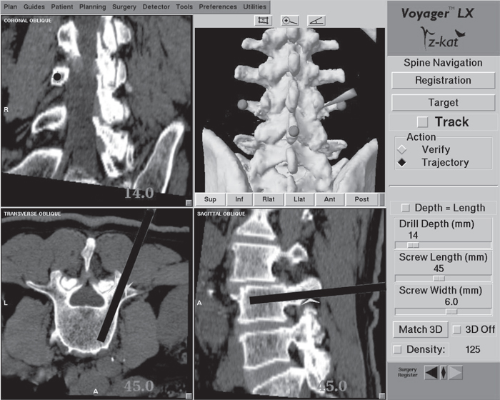
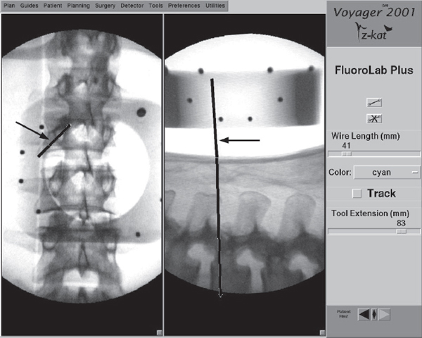
60 The management of spinal disorders has been greatly influenced by the development and use of screw-based fixation devices. Accurate placement of these screws requires the spinal surgeon to have a precise orientation to that part of the spinal anatomy that is not exposed in the surgical field. Although conventional intraoperative imaging techniques such as fluoroscopy have proven useful, they are limited in that they provide only two-dimensional imaging of a complex three-dimensional structure. Consequently, the surgeon is required to extrapolate the third dimension based on an interpretation of the images and knowledge of the pertinent anatomy. This “dead reckoning” of the anatomy can result in varying degrees of inaccuracy when placing screws into the unexposed spinal column. Several studies have shown the unreliability of routine radiography in assessing pedicle screw placement in the lumbosacral spine. The rate of disruption of the pedicle cortex by an inserted screw ranges from 15% to 31% in these studies.1–4 The disadvantage of these conventional radiographic techniques in orienting the spinal surgeon to the unexposed spinal anatomy is that they display, at most, only two planar images. While the lateral view can be relatively easy to assess, the anteroposterior (AP) or oblique view can be difficult to interpret. For most screw fixation procedures, it is the position of the screw in the axial plane that is most important. This plane best demonstrates the position of the screw relative to the neural canal. Conventional intraoperative imaging cannot provide this view. An additional concern of conventional intraoperative imaging is the radiation exposure experienced by the surgical team and the patient. Rampersaud has demonstrated that compared with other orthopedic procedures utilizing intraoperative fluoroscopy, spinal procedures potentially result in a 10–12-fold increase in radiation exposure because of such factors as backscatter radiation and the increased energy levels needed to image the lumbar spine. This creates a potentially significant hazard to those individuals who perform a high volume of complex spinal surgery.5 Computer-assisted spinal surgery, or image-guided spinal navigation, is a computer-based surgical technology designed to improve intraoperative orientation to the nonvisualized anatomy during complex spinal procedures.6,7 It provides the spinal surgeon with the ability to manipulate multiplanar computed tomographic (CT) or fluoroscopic images during the procedure to gain a greater degree of orientation to the surgical anatomy, optimizing the precision and accuracy of the surgery. An additional advantage is that, compared with conventional intraoperative imaging, image-guided navigation eliminates or significantly reduces radiation exposure to the surgical team. Computer-assisted spinal surgery facilitates surgical accuracy by matching spinal image data to the corresponding intraoperative anatomy. It is based on the principle that both the image data and the surgical anatomy represent a three-dimensional coordinate system. Each point in the image dataset and in the surgical field has a location in space defined by specific x, y, and z Cartesian coordinates. Using defined mathematical algorithms, a specific point in the image dataset can be “matched” to its corresponding point in the surgical field. After matching a limited number of these points together, any point in the surgical field can then be selected and its corresponding point in the images displayed in several planes, giving the surgeon a greater degree of orientation to the pertinent surgical anatomy. There are currently four general types of computer-assisted spinal surgery available. CT-based navigation uses CT images of the patient acquired prior to the surgery. Conventional intraoperative imaging is not necessary. During navigation the surgeon is presented with reformatted CT images in multiple planes, with the selected screw entry point and trajectory superimposed on the images (Fig. 60.1). This information updates in real time as adjustments are made to the selected trajectory in the surgical field. Fluoroscopic navigation uses a standard AP and lateral image of the spinal anatomy acquired just before surgery begins. No additional intraoperative imaging is needed. The selected trajectory information is superimposed on the AP and lateral images on the workstation screen (Fig. 60.2). In contrast to CT-based navigation, no axial image is available. The advantage of fluoroscopic navigation is that it uses less radiation than conventional fluoroscopy and does not require a preoperative CT scan, as CT-based navigation does. Intraoperative isocentric fluoroscopic navigation is a variation of standard fluoroscopic navigation. It acquires images just prior to surgery by rotating the specialized C-arm in a 180-degree arc around the patient. These images can then be reformatted to provide images in the axial and sagittal planes, as in CT-based navigation, but without the need to acquire a preoperative CT scan. Although the images are not of the same quality as a standard CT image set, they are adequate for navigation in most cases. Intraoperative CT navigation is the most recent advancement in computer-assisted surgery. It consists of a portable CT scanner that uses flat-panel detector technology to improve intraoperative image acquisition and quality. The scanner has a configuration similar to a standard C-arm fluoroscope. In addition to being able to acquire standard AP and lateral images, its C-arm configuration can be “closed” to completely encircle the patient. This allows the flat-panel detector to be swept in a 360-degree arc around the patient, significantly improving the acquired image quality. The reformatted images are similar in quality to conventional CT imaging and superior to isocentric fluoroscopic imaging. The use of automated registration makes this form of computer-assisted spinal surgery very applicable to minimally invasive surgery. Fig. 60.1 Workstation screen demonstrating navigation for an L3 pedicle screw. The common components of most navigation systems include an image-processing computer workstation interfaced with a two-camera optical localizer (Fig. 60.3). When positioned during surgery, the optical localizer emits infrared light toward the operative field. A hand-held navigational probe mounted with a fixed array of passive reflective spheres serves as the link between the surgeon and the computer workstation (Fig. 60.4). Passive reflectors can also be attached to standard surgical instruments. The spacing and positioning of the passive reflectors on each navigational probe or customized trackable surgical instrument is known by the computer workstation. The infrared light that is transmitted toward the operative field is reflected back to the optical localizer by the passive reflectors. This information is relayed to the computer workstation, which can then calculate the precise location of the instrument tip in the surgical field as well as the location of the anatomic point on which the instrument tip is resting. The establishment of a spatial relationship between the image data and the surgical anatomy is achieved through a process termed “registration.” Three different registration techniques can be used for spinal navigation: paired-point registration, surface matching, and automated registration. Paired-point registration involves selecting a series of discrete corresponding anatomic points in a CT dataset and in the exposed spinal anatomy. These points typically are the tip of a spinous or transverse process or the apex of a facet joint. Following the selection of one of these points in the CT image, the tip of the navigation probe is placed on the corresponding point in the surgical field and the reflective spheres on the probe handle are aimed toward the camera. Infrared light from the camera is reflected off the spheres, back toward the camera, and the reflection signal is sent to the computer, which does the calculations to determine the spatial position of the probe’s tip and the anatomic structure it is resting on. This effectively “links” the point selected in the image data with the point selected in the surgical field. When a minimum of three such points are registered, the probe can placed on any other point in the surgical field, and the corresponding point in the image dataset will be identified on the computer workstation.8 Fig. 60.2 Workstation screen of a fluoroscopic navigational system. Standard AP and lateral views are provided with superimposed trajectory lines (arrows).
Computer-Assisted Spinal Surgery
![]() Principles of Computer-Assisted Spinal Surgery
Principles of Computer-Assisted Spinal Surgery
Related posts:

Stay updated, free articles. Join our Telegram channel

Full access? Get Clinical Tree


