ROBERT A. CHRISTMAN AND MARY OEHLER
X-rays interact with an image receptor and form the latent image (an invisible change that represents the object that was radiographed) after passing through the patient. The visible (manifest) radiographic image is produced following processing of the latent image. Conventional radiography has, for more than 100 years, employed as an image receptor the film–intensifying screen combination. The exposed film must be processed with chemicals to produce the manifest image, which is then viewed on a light box, cataloged, and physically stored. With the advent of filmless or digital radiography (DR) in the late 20th century, an electronic detector has replaced the film–screen image receptor. The latent image formed on the electronic detector is measured and converted into an analog electrical signal that is then converted into a digital signal, which is processed by a computer, creating a digital image that is viewed on a monitor. These images are then stored electronically.
No matter what image acquisition system is used to process the image, however, they all depend on the same x-ray machine. Furthermore, the four quality factors that the limited x-ray machine operator (LXMO) controls before the x-ray beam strikes the image receptor, radiographic density, contrast, recorded detail, and distortion, apply to DR as well. These factors are discussed in detail in Chapter 2.
Attempts have been made to categorize the different types of DR. They have been categorized by form factor (cassette-based vs. no cassette), image acquisition time (immediate vs. longer), x-ray signal conversion (indirect vs. direct), and linkage to computer (indirect vs. direct). We have found it useful to categorize by the type of detector system, but will include reference to the other categorizations when appropriate.
DIGITAL RADIOGRAPHY DETECTOR SYSTEMS
Four DR detector systems are available for podiatric use: the photostimulable storage phosphor (PSP) detector, charge-coupled device (CCD) detector, complementary metal-oxide semiconductor (CMOS) detector, and flat-panel detector (FPD). Each has three components: the capture element, coupling element, and collection element. The x-ray may be captured by a photostimulable phosphor, scintillation phosphor, or a photoconductor. The signal generated by the capture element is transferred or coupled to the collecting element via an optical system, photodiode, or a photoconductor. The element that collects the x-ray–generated signal may be a photodetector, CCD camera, thin-film transistor (TFT) array, or CMOS.
The collection element sends an electric signal to an analog-to-digital converter (ADC), which then goes to a computer that has appropriate software installed. Computer algorithms convert the digital data into a digital image that is then viewed on a monitor.
The DR field is growing and changing rapidly. The descriptions of the various technologies below are generic, since there is constant development of new and improved devices. However, the emphasis is on application to podiatric radiology.
Photostimulable Storage Phosphor Detectors
Also known as computed radiography (CR), the PSP detector is widely used in podiatric settings because it has been available the longest. The initial investment also is less expensive compared to the remaining DR systems, which may also require retrofitting of existing x-ray equipment (in particular, the orthoposer). Although several newer DR detector systems have become available, CR will more than likely prevail for several years to come.
The capture element is a photostimulable storage phosphor, barium fluorohalide with europium. The PSPs are incorporated into a storage phosphor screen. Whereas x-ray film and intensifying screens are housed in a cassette, the PSP screen is housed in what is called an imaging plate (IP). The IP is not linked directly to a computer.
The PSP electrons are energized when exposed to x-rays and form the latent image. (At least half of these electrons return to their ground state immediately and release light when doing so, but the remaining electrons may stay in an excited state for several hours. Furthermore, in 8 hours the latent image will lose approximately 25% of its energy. Therefore, the IP should be processed soon after exposure.) When the IP is placed into a PSP reader, the phosphor screen is removed and scanned by a laser beam; this stimulates many of the remaining excited electrons to their ground state and the PSPs emit light, referred to as photostimulable luminescence (PSL). The light is collected and directed to a photodetector via an optical system. The photodetector measures the light signal, then amplifies the light and sends it as an electrical signal to an ADC. The x-rays, therefore, are indirectly converted into an electrical signal. Lastly, the phosphor plate is exposed to a bright light that erases the latent image and any remaining excited electrons so that the IP can be used again.
The PSP IP is always “on,” meaning that it is sensitive to scatter radiation; therefore, it should not be stored in a radiography room. Since it is also sensitive to background radiation, if the IP is not used for a period of time (e.g., over the weekend), it should be erased again before reusing it.
Of all the forms of DR, CR is the only one to functionally emulate the film–screen paradigm; similarly, CR shares some of its limitations. The image receptor is “cassette-based” (the IP), which has to physically be transferred to a “processor” (the PSP reader), which will likely be in another room. The IP can be easily damaged, especially if dropped while transporting the cassette to and from the IP reader. The phosphor screen can be processed in two ways: after “manually” removing it from the IP, or the IP is placed into a processor that “automatically” reveals the phosphor screen for processing (Figure 3-1). In either case, the time to “process” the image by the PSP reader takes approximately 1 minute. These are a few of the limitations of CR that have motivated manufacturers to develop FPD technology. On the other hand, because of its mobility, the cassette-based system allows for a multitude of positioning techniques.
Charge-Coupled Device Detector
The CCD detector is the same light sensor that is used in most digital cameras. The detector is not housed in a cassette and requires modification of the orthoposer because the CCD detector can be rather large and bulky (Figure 3-2). It uses a phosphor scintillator, either cesium iodide (CsI) or gadolinium oxysulfide (GdOS), which emits light when exposed to x-rays. Light from the scintillator is transferred to a CCD by an optical system (lenses or fiber optic tapers) that demagnifies the light. After collecting the light, the CCD detector produces an electrical signal that is then converted into a digital signal by an ADC. Similar to CR, the x-rays are converted indirectly into an electrical signal; however, unlike CR, the CCD detector is directly linked to a computer. The image acquisition time is 20 to 30 seconds.
Some consider CCD DR an “interim” technology until FPDs become more readily available. Though it is an improvement over CR, eliminating the cassette with separate PSP reader and reducing the time for image development, the optical collecting element reduces image quality during demagnification. Also, the production cost of CCDs is high, and they are susceptible to radiation damage.
Flat-Panel Detector
A flat-panel detector, often integrated into the orthoposer, is used for direct and indirect conversion DR; however, it is totally different in design and structure from the PSP device. It consists of an x-ray absorber material (photoconductor or scintillator) that is coupled to a TFT array. The FPD converts the absorbed x-rays into an electrical signal directly (direct conversion DR) or indirectly via light (indirect conversion DR). Similar to CR and CCD-based DR, a computer then processes the electrical signal from the collection element that has been converted into a digital signal by an ADC. (FPD systems have also been referred to as active matrix flat-panel imager (AMFPI) systems.)
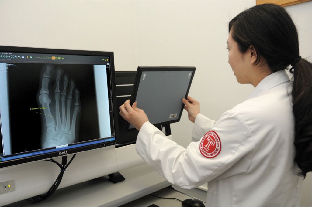
FIGURE 3-1. “Automatic” PSP reader. Cassette is being fed into reader from the right. This reader is a tabletop unit that extends to the left, behind the monitor.
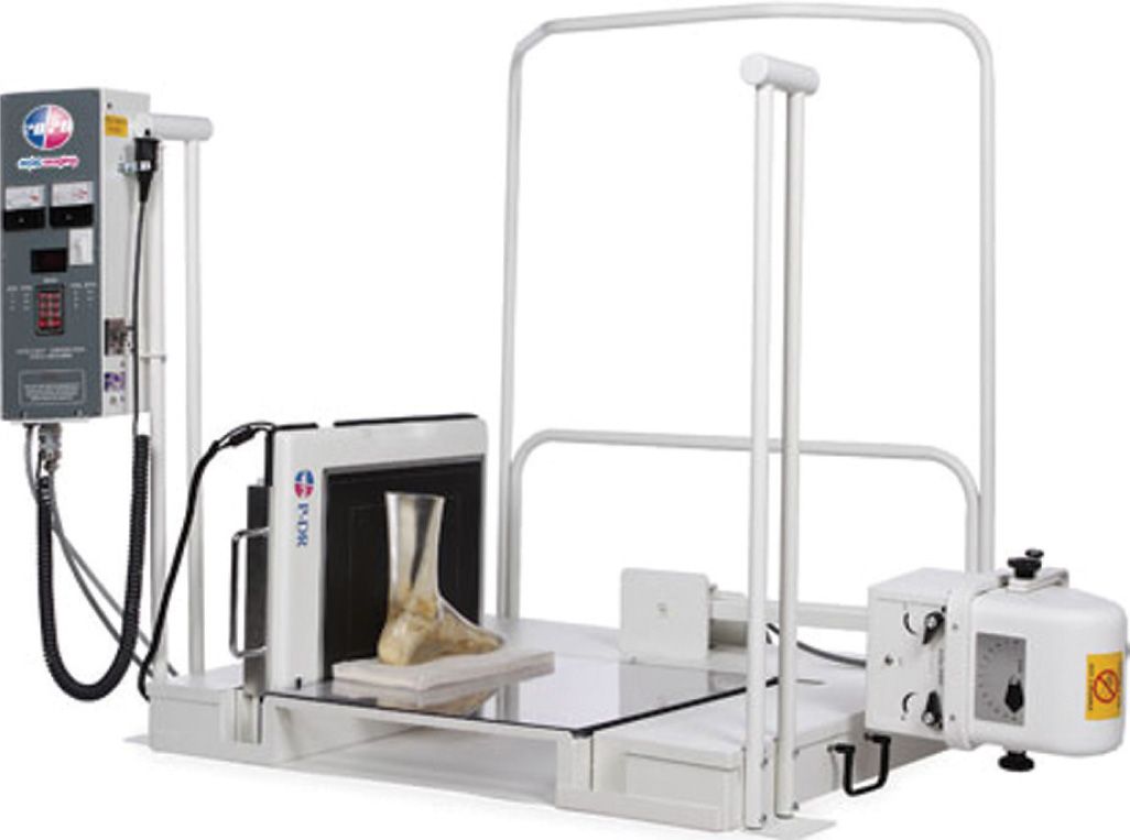
FIGURE 3-2. CCD detector system with retrofit orthoposer base. This detector unit can be moved to accommodate weight-bearing dorsoplantar and lateral positioning techniques. (Courtesy of 20/20 Imaging, LLC, Crystal Lake, IL.)
The direct conversion DR system uses the photoconductor amorphous selenium (a-Se) instead of a scintillator to absorb the x-rays. The a-Se is coupled to a TFT array so that the x-rays are directly converted into an electrical signal. The intermediate scintillation layer is not necessary and is eliminated; the a-Se serves as both the capture and coupling elements by converting x-rays directly to charge.
Similar to CCD-based DR, the indirect conversion DR system uses a phosphor scintillator (CsI or GdOS) that emits light when exposed to x-rays. But that is where the similarity ends. Light from the indirect conversion DR phosphor scintillator is transferred to a TFT array by an amorphous silicon (a-Si) photodiode array, an electronic element that converts light into charge. After collecting the light, the TFT array produces an electrical signal.
Complementary Metal-Oxide Semiconductor Detector
The CMOS system has had problems that slowed the introduction of this technology into medicine. In particular, the presence of electronic noise has hindered development; however, there has been some success with small detector sizes, and there is at least one CMOS detector available for podiatric use. Like the CCD detector, the orthoposer must be modified.
Related posts:


Stay updated, free articles. Join our Telegram channel

Full access? Get Clinical Tree


