Principles of Biomechanical Radiographic Analysis of the Foot
WILLIAM H. SANNER AND KENDRICK A. WHITNEY
The purposes of using radiographs to analyze foot biomechanics include determination of foot stability (and evaluate the foot as a base for locomotion), to correlate with the physical exam, and to plan surgery.1,2 This chapter describes a system based on the concepts of stability that can be used to analyze the biomechanics of the foot.
REVIEW
The majority of foot radiographs used to assess foot mechanics are weight bearing so as to more closely approximate osseous relationships in stance and gait.3 Approximating dynamics and standardization are also why foot radiographs are taken in the angle and base of gait.3–5 The forces are not the same, however, because midstance is dynamic and radiographs represent a static situation. Nevertheless, radiographs can indicate how the weight-bearing foot reacts in a closed kinetic chain environment and how it interacts with ground reactive forces.
Although specialty views, such as Harris–Beath,6 and an anterior axial view of the foot can be used,7 the primary views used are the dorsoplantar and lateral.2–4 The dorsoplantar view reveals the transverse plane relationships within the foot, and the lateral view clarifies the sagittal plane relationships.2,3,7,8 The dorsoplantar and lateral views are used together to infer frontal plane relationships. The anteroposterior axial view of the foot additionally provides direct frontal plane relationships.7,9
Positioning of the patient is very important, because the osseous relationships revealed by the radiograph can be altered dramatically if the patient is not in a relaxed angle and base of gait.10–14 Standardized positioning is essential for reproduction and accuracy of the radiograph that represents the foot’s interaction with ground reactive forces.
The foot bones have a genetically predetermined shape and alignment, which is secondarily modified by stress that originates intrinsically and extrinsically to the foot.15 This phenomenon is generally referred to as Wolff’s law, and the clinician can assess such stresses by observing the trabeculae and bone shapes.16,17 Trabeculae are parallel to the direction of stress. Bone shape evolves as the result of compression and tension experienced by the bone when standing and walking. Thus, if compression is not even across a joint, the margins of the joint change shape, reflecting the abnormal application of force on the joint. What may begin as minor asymmetry of force applied to a joint may eventually result in the joint developing a shape that perpetuates the reduced efficiency of the joint. The shape of the foot bones is crucial, for the foot is like a bridge that must carry the superimposed body.18,19
To meet the requirements of gait, the footbridge bones must be well aligned to provide stability, yet mobile enough to help absorb shock and adapt to terrain while walking. The foot must also not become so flexible that it is unstable during midstance and propulsion, to allow timely first metatarsophalangeal joint dorsiflexion.20–22 The ideal foot is not the most stable or the most unstable, but rather a balance between the two conditions.
When clinicians review foot radiographs and examine the foot for the purpose of analyzing it as an instrument for locomotion, they are looking for evidence of stability. When describing foot radiographs, evaluators compare the alignment of two segments by describing the distal segment relative to the proximal segment. It should be kept in mind that the distal part cannot be stable unless the proximal segment is stable.21,23
TERMINOLOGY
Throughout this chapter the terms position, stability, and alignment are used. The key to understanding the concepts described in this chapter is to have a sound understanding of these terms.
Position
According to Webster’s New World Dictionary of the American Language, position means “the place where a thing is … in relationship to others.”24 Position of a joint describes where, in the range of motion of that joint, the respective bones are placed or situated. Therefore, to give the position of a joint, a reference must be provided. Such reference may be degrees or angulation relative to a proximal segment (e.g., the calcaneus is 5° inverted relative to the leg) or relative to a neutral position (the ankle is 10° dorsiflexed). Position does not imply motion or direction of motion. For example, an ankle may be 10° dorsiflexed, but this does not indicate whether it is dorsiflexing, plantarflexing, or stationary, for these are terms of motion.
If the clinician does not have a reference to compare the relative position of two bones, then the position of that joint or series of joints cannot be determined. For example, one must first determine the subtalar joint neutral position before you can determine if the position of the subtalar joint is pronated, neutral, or supinated. The terms plantarflexed/dorsiflexed, abducted/adducted, and inverted/everted can be used when describing radiographs of the foot, because these terms compare one foot segment to another.
Though the subtalar joint neutral position may not be determined radiographically, the attitudes of the pronated and supinated foot may be used to describe foot morphology.
Stability
Stability of an object is the “state of being fixed,” “resistant to change,” and the “ability to return to its original position.”24 Thus, a stable object “is not easily moved or thrown off balance,” “is not likely to break down or fall apart,” “is lasting and enduring,” and “is able to return to its original position after being displaced.”
Similarly, the foot must, for many years, be able to adapt to uneven terrain, be a rigid lever for propulsion, and yet return to its original position at the beginning of each step.2 A foot that is too stable cannot adapt to uneven terrain because it is too “resistant to change.” A foot that is not stable cannot act as a rigid lever or return to its original position once displaced. The degree of stability is of importance to proper foot mechanics and is a quality that can be inferred in radiographs based on the alignment of weight-bearing bones.
Alignment
The term alignment means “arrangement in a straight line,” and to align means “to bring into a straight line.”24 Thus, the bones in a well-aligned foot have straight, linear relationships. When performing biomechanical radiographic evaluation of the foot, the term alignment should be used instead of position. This is because a straight line can be used as a reference and because the concept of linearity is the foundation for the concept of stability.
In general, most objects are more stable when they are well aligned because they bear loads better (Figure 12-1). The linear relationship of a well-aligned, load-bearing object allows even distribution of the imposed stress of the load and reduces the tendency for bending. In the foot, the relative stability of joints is evaluated. When a joint is loaded, it has more inherent stability when arranged in a straight line.
The foot does not have perfect linear relationships because such alignment would provide too much stability. As mentioned earlier, a foot that is too stable cannot serve the dynamic functions required for normal locomotion. In contrast, a foot with bones too greatly angulated is unstable and collapses under the load.
PRINCIPLES OF STABILITY
Joints are most stable when they are compressed and not subject to angular moments, that is, rotational forces.21 The most stable joint is linear and, with applied force, directed along the joint axis. The compression is distributed evenly and perpendicular to the joint surface21 (Figure 12-2). This situation creates maximum compression and stability. A stable joint must have an even compression across its joint surface. The radiograph should show the joint space to be congruent (even) for the joint to have optimal transmission of compression. An angled, subluxated or dislocated joint does not have even compression across the joint surface and so is not stable.
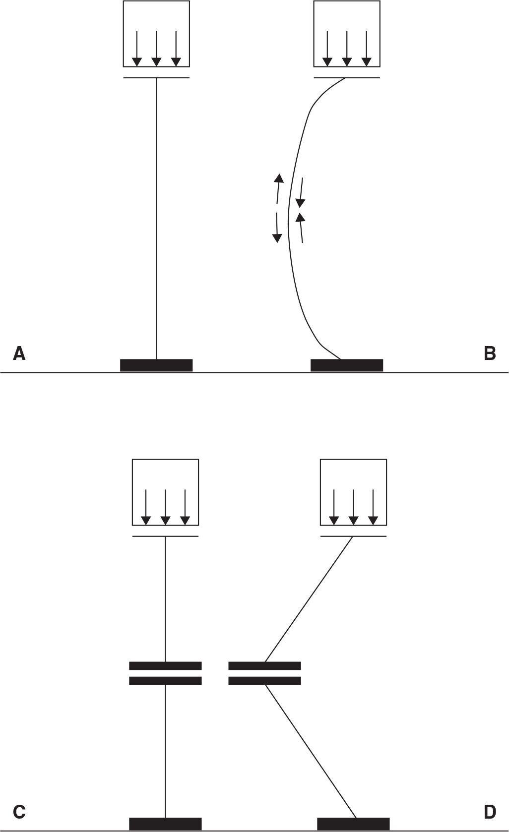
FIGURE 12-1. In general, a straight load-bearing column (A) is more stable than one that is curved (B) or angled (D). A curved or angled load-bearing column structure when compressed develops a compression side and a tension side. Even if the nonlinear load-bearing column is stable, the uneven load borne through the nonlinear structure is more likely to result in fatigue of the column and eventually may lead to collapse. If the linear column has a joint that is properly aligned with the loading force (C) (perpendicular with the loading force vector, which passes through the joint), the column continues to support the load because no rotational force (moment) is exerted at the joint.
Therefore, the most stable foot would be one that has only straight joints, with no angulation of its various osseous segments. It presents with even joint spaces, and perpendicularity of all forces applied to the joint axes and surfaces. Because each osseous segment is well aligned relative to its neighbor, the entire foot would be stable.
A force vector that creates rotation at a joint is called a moment and the resulting rotation is the opposite of stability. The unstable foot is one that has an obvious angulation between the osseous segments, uneven joint spaces, and uneven compression of the joints. It has a net force vector that is not perpendicular to the joint axes, so that a moment is created. Joint angulation (lack of alignment) and nonperpendicularity of the net force to the joint surface and axis result in rotation, which is the opposite of stability.
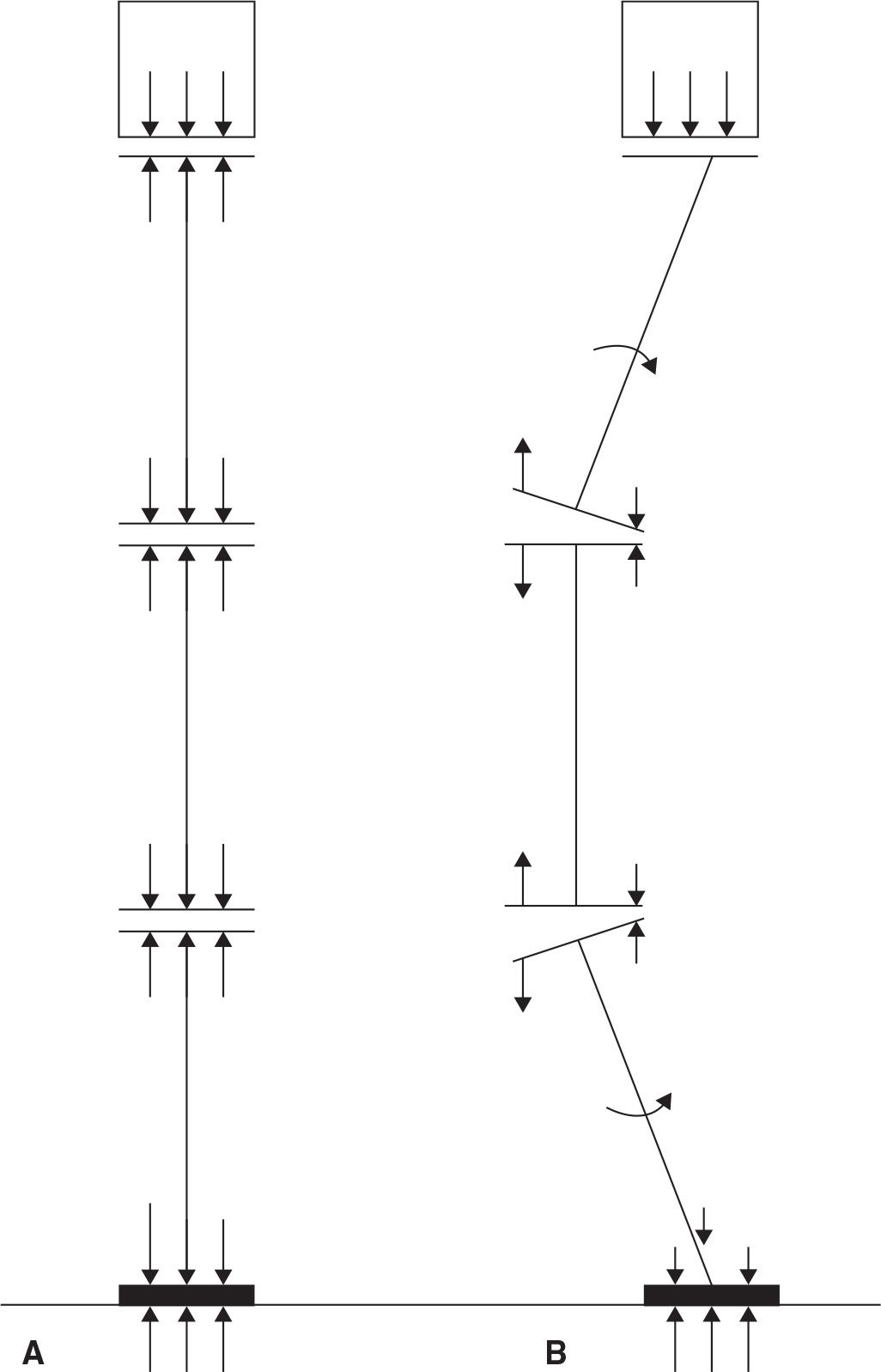
FIGURE 12-2. A: A column that has a series of segments is stable so long as the joints between the segments have even compression across the joint surface. Even compression is achieved when the joints are aligned so that the joint surface is perpendicular to the compressive force vector and the force vector passes through the joint. B: When the joints are not aligned linearly with the compressive force, a moment (rotational force) is created at the joint and the joint rotates instead of bearing the load.
When the foot pushes down on the ground, the ground pushes upward; this is ground reactive force.25,26 The majority of ground reactive forces are not directed toward the more vertically oriented foot joint surfaces or axes27 (Figure 12-3). The foot develops stability, even though the net force vector acting on the foot is not directed perpendicular to most of the joint surfaces. The foot tension bands (trusses) are the key elements in changing how the largest vertical component of ground reactive force is directed through the foot.19,28–36 The plantar fascia and ligament truss systems convert and compress the vertically directed forces into a series of straight, self-locking wedges that prevent rotation to occur.28,29,34–39 This rotation is forefoot dorsiflexion on the rearfoot.
First metatarsophalangeal joint dorsiflexion during propulsion winds the plantar aponeurosis around the first metatarsal head, thereby shortening the plantar aponeurosis in a windlass fashion. The winding of the plantar aponeurosis around the first metatarsal head plantarflexes the forefoot on the rearfoot, thereby supinating the foot and increasing foot stability by resisting rotation of the forefoot on the rearfoot (dorsiflexion). This wrench-like mechanism is called the windlass effect.28 Timely dorsiflexion of the first metatarsophalangeal joint during propulsion increases foot stability at a time when ground reactive forces are the greatest. The extrinsic and intrinsic foot muscles aid the plantar aponeurosis in stabilizing the forefoot on the rearfoot, specifically the medial longitudinal arch. Thus, the foot was designed to function well in the face of large vertical forces, as long as the foot is properly aligned.
The foot is not well designed to resist the influences of transverse and frontal plane forces, because there is no mechanism designed to oppose these forces. Instead, muscles and ligaments must resist transverse and frontal plane forces. Only when the foot is well aligned and inherently stable, with ground reactive forces that are principally sagittal plane in nature and not converted into transverse and frontal plane moments, can the muscles and ligaments decelerate the transverse and frontal plane joint motion, converting the rotational potential into compressive forces in the joints (Figure 12-4). When the foot is unstable, more muscle activity is necessary to improve stability.40
Related posts:

Stay updated, free articles. Join our Telegram channel

Full access? Get Clinical Tree


