Fig. 1
Arcadis Orbic from Siemens
In this way a 3D data cube is obtained from the isocentre of the C-arm with a side length of about 12 cm. The maximum resolution in the centre of the cube is approximately 0.47 mm. Within this data cube, any number of planes can be viewed at an in-line workstation, this technique is also called cone-beam CT. It has become established practice to set the standard planes known from CT diagnostic procedures, including for documentation. This allows a continuous standardised assessment, the three-dimensional orientation is easier, and comparison with any existing preoperative CT series is readily possible. In contrast to the conventional computer tomography, the position between the scanned object and the 3D C-arm is unknown, therefore the adjustment of the standard planes is an important step. For special questions, any number of free adjustable planes can be set, such as axial imaging of one single screw in order to be able to assess its exact course. Therefore the adjustment of the views are oriented by the position of the screw. The data are portrayed as high-contrast imaging and strong density differences, and the definition of bony structures, in particular, are optimally portrayed in this way.
Artefacts due to inserted implant material cannot be avoided. The less metal there is in the scan field, the fewer the number of artefact formations as well (Fig. 2).
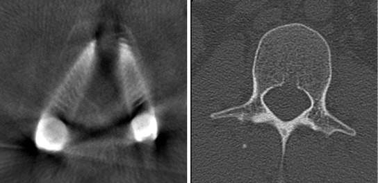
Fig. 2
Image quality with and without implants
In the area of the lower extremities, superimpositions from the opposite extremity can be avoided by excluding it from the scan field, for example by bending the leg. By positioning the patient on a metal-free radiolucent carbon leg plate or on a combined carbon and metal leg plate, artefacts from the operating table can to a large extent be excluded. The patient’s own movements must be avoided during the scan. The time of the scan is specified by the operator and typically occurs following the completion of the essential parts of the reduction and osteosynthesis, after the operator has assumed that the procedure has been correctly performed on the basis of two-dimensional fluoroscopy.
The additional intraoperative time required includes the time for positioning the image converter, the duration of the scan (2 min with the Iso-C3D or 1 min with the more recent generations of the Arcadis Orbic 3D, in each case for 100 images), the time to the primary calculation of the 3D dataset of approximately 15 s and the time for the surgeon to process and assess the images.
The average time needed to perform and analyse the 3D scan is about 5 min, depending on the fracture type and the surgeon’s experience.
All scans performed intraoperatively must be documented postoperatively by the surgeon in charge and duly archived, e.g. by connecting to an electronic image data storage system via a network.
1.1 3D Navigation with the Mobile 3D C-Arm
In addition to the multislice imaging of cross-sectional planes, an additional area of use of the 3D image converter is 3D navigation.
Navigation is particularly used in complex fractures in the area of the spinal column and pelvis, but also in challenging procedures in the area of the foot and ankle.
By visualising instruments in the three-dimensional dataset, its use allows surgical procedures in complex anatomical regions without a direct view of the operative region. The general benefits over conventional procedures include reduced radiation exposure for patients and surgical team, as well as the possibility of being able to operate more precisely using a minimally invasive procedure. This results in increased safety and quality of outcome for patient and surgeon. The disadvantage may be a longer operative time depending on the region [1, 2].
3D navigation requires a 3D image intensifier and a navigation system with an optoelectronic camera. A reference marker is attached to the patient’s bone in the vicinity of the region to be operated upon. After registering the marker, a 3D scan is performed. This 3D dataset is transferred to the navigation system. Surgical navigation is then performed using calibrated instruments in the corresponding section of the image dataset. After implant positioning, another 3D scan is performed to verify the placement. Where it is useable in the anatomical region concerned, the indications for the use of 3D navigation are discussed in the following sections.
2 Spinal Column
The incidence of injuries of the spinal column is 64/100,000 in Germany.
Although overall there is an equal sex distribution, two frequency peaks may be identified: at a young age men are frequently affected, whereas at an older age women tend to be affected more.
Differences in the causes of trauma are also apparent according to the age structure: in younger patients, high-speed trauma such as traffic accidents involving cars and motorbikes, as well as sporting injuries in extreme sports such as climbing and paragliding, are frequently the causes of fractures.
In elderly patients, osteoporosis resulting in a fracture of the vertebral body is considerably more common.
Overall, the cervical spine and the thoracolumbar junction are the sections most commonly affected.
Common to all injuries is the fact that there is a risk of injury to neurological structures because of the vicinity of the spinal cord and nerve roots in an unstable situation.
In 40 % of cervical spine injuries and 20 % of fractures in the area of the thoracic and lumbar spine there is an accompanying neurological impairment, which can range from paraesthesia to symptoms of a transverse lesion.
Fractures in the area of the upper cervical spine and their treatment concept are described below first of all and this is then followed by an overview of fractures in the lower cervical, thoracic and lumbar spine due to their similar anatomical structure.
3 Upper Cervical Spine
The upper cervical spine is composed of the atlas and axis.
The atlas consists of an anterior and a posterior arch and allows sliding and extension/flexion movements over its joint surfaces in the head region.
The axis is seated below the atlas and is connected to it via a peg, known as the dens. Rotational movements in the area of the head are undertaken through this jointed connection.
Laterally to the cervical spine, the vertebral arteries pass normally from the sixth cervical vertebra through the vertebral foramina in the direction of the head.
Typical injuries to the upper cervical spine are dens fractures and atlas arch fractures. If there is a risk of respiratory paralysis due to the vicinity of the dens to the brainstem in the event of dislocation, there is a strong indication for surgery. But many dens fractures in old patients are rather stable and will result in a stable pseudarthrosis, with no need of an require upfront fusion.
If there is an indication for fixation, screws are usually used to stabilise the fracture.
The challenging aspect of fracture care is the exact placement of the osteosynthesis without injuring the spinal cord or perforating the vertebral artery running through the vertebral foramen (Fig. 3)
.
Fig. 3
C1 vertebral foramen of the vertebral arteries
In treatment of dens fractures, the stabilization is possible in different ways, depending of the fracture type and the age of the patient. Using the anterior approach, reduction is usually obtained by the insertion of two traction screws. In order to be able to check the position of the screws, Kirschner wires are first inserted temporarily in the desired direction. The position of the wires is then checked by fluoroscopy. One problematic aspect of this procedure is that a slight malposition can result in injuries to the spinal marrow.
In this case, 3D imaging with the C-arm is particularly valuable.
Following insertion of the Kirschner wires, a scan can be performed first of all to check their position and secondly to correct this if necessary.
After placement of the screws, a further scan is often also performed, the reason for this being that the diameter of the screws exceeds that of the K wires, so that perforation of the bone can be excluded by the scan (Fig. 4).
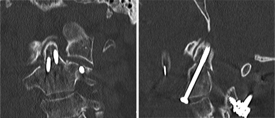
Fig. 4
Osteosynthesis of a dens fracture with screws
4 Lower Cervical Spine, Thoracic Spine and Lumbar Spine
The fractures predominantly found in the lower cervical spine and in the thoracic and lumbar spine are those in the area of the vertebral bodies.
Surgical treatment is frequently necessary in these cases, which is partly due to the vicinity of the spinal marrow and hence the threat or actual presence of neurological symptoms.
To relieve the pressure on the fractured vertebral body, the motion segments lying above and below the affected vertebra must be rigidified.
To this end, two screws are inserted into each of the unaffected vertebral bodies through the vertebral pedicles. The screw heads are then connected by a rod and the transmission of force is diverted away from the fractured vertebra.
The challenge of the procedure here is the exact placement of the above mentioned pedicle screws. These must be positioned from the back of the vertebra through the vertebral arch. There is the risk here of damaging the spinal column running through the vertebral arches or the nerve roots running above or below with the screw.
Similarly to the wire described in the upper cervical spine, a wire-like Jamshidi needle is inserted into the pedicle in this operation as well. This needle traces the planned route of the pedicle screw and the entry point and the course in the pedicle can be altered under fluoroscopy. A guide wire is then placed through this needle for the subsequent screw and the needle is removed.
A 3D scan can also be performed here to check the exact position of the wires.
Following the insertion of the pedicle screw and completion of the instrumentation by the assembly of the rod, a further scan can be taken. This can be used to check firstly the position of the osteosynthesis material, but also secondly the quality of the fracture reduction.
On a critical note, it should be pointed out that intraoperative 3D imaging can in some cases come up against its limits in the thoracic spine. The chest cage structures surrounding the cervical spine and in some cases those of the upper extremities can reduce the image quality in this area.
Nevertheless, despite these problems, the 3D scan is superior to traditional fluoroscopy where imaging of the anatomy is concerned.
5 3D Navigation in the Area of the Spine
As well as the “simple” multislice verification of the position of the osteosynthesis material and the quality of the reduction, 3D imaging by navigation can be used.
The aims are increased accuracy in the placement of the pedicle screws and a reduction in the radiation burden as a result of a shorter fluoroscopy time.
Navigation in the area of the spine was introduced because of the extremely high number of pedicle screw malpositions. There were reports of up to 30 % malpositions in the cervical spine and up to 55 % malpositions in the area of the lumbar spine [3, 4].
In the subsequent studies, the malposition rate was reduced to 0–8 % following the introduction of navigation procedures [1, 5].
In one study, which compared navigated screw placement with conventional screw placement, it was shown that in addition to the greater accuracy of the pedicle screw position, a marked reduction in fluoroscopy time was achieved [5].
Navigation in the area of the cervical spine has not been a standard procedure so far. Dens screws and transpedicular screw placements in the area of the axis are described. However, robust comparative studies demonstrating a benefit of the navigated group over the non-navigated group are lacking.
6 Pelvis
6.1 Posterior Pelvic Ring
The placement of screws in the area of the posterior pelvic ring in the case of fractures of the sacrum as well as dislocations in the area of the iliosacral joint is challenging because of the complex anatomy.
The posterior pelvic ring is surrounded by nerves and blood vessels and the bony corridors for inserting a screw are narrow.
As a result, extensive fluoroscopy is frequently required to check the conventional percutaneous insertion of screws. Exposure times of up to 10 min are reported. This is complicated by the difficulties that occur in obtaining the appropriate projections for assessing the correct implant position depending on the patient’s stature. Using 3D scans, both the position of the initial wire and screws, as well as the reduction result obtained, can be checked considerably better.
6.2 Acetabulum
The gold standard in the treatment of acetabular fractures is an open reduction and plate osteosynthesis. Surgical accesses are often very extensive and are associated with corresponding soft tissue trauma.
Depending on the fracture morphology, percutaneous screw osteosynthesis is also possible for fractures in the area of the acetabulum. The prerequisite for this is that the fractures are not dislocated or only slightly so. However, because of the complex anatomy of the acetabulum, here too screw placement is extremely challenging for the surgeon. An intra-articular screw position causes impairment of movement in the hip, while perforation of the pelvis can lead to vascular and nervous damage. For this reason, the benefits of the use of intraoperative 3D imaging described for the posterior pelvic ring apply here as well.
Related posts:
 of Implant Osseointegration by Means of a Reconstruction Algorithm on Micro-computed Tomography Images
Fusion for Computer-Assisted Bone Tumor Surgery
Planning of Periacetabular Osteotomy (PAO)
Robotics for Musculoskeletal Surgery
of the Art of Ultrasound-Based Registration in Computer Assisted Orthopedic Interventions
Reconstruction-Based Planning of Total Hip Arthroplasty
of Implant Osseointegration by Means of a Reconstruction Algorithm on Micro-computed Tomography Images
Fusion for Computer-Assisted Bone Tumor Surgery
Planning of Periacetabular Osteotomy (PAO)
Robotics for Musculoskeletal Surgery
of the Art of Ultrasound-Based Registration in Computer Assisted Orthopedic Interventions
Reconstruction-Based Planning of Total Hip Arthroplasty
Stay updated, free articles. Join our Telegram channel

Full access? Get Clinical Tree


