Fig. 1
A 3D model of the pelvis with the osteotomized acetabulum is depicted. The Ganz PAO allows for reorientation of the acetabulum in all degrees of freedom, since there are no ligamentous restraints limiting reorientation. The large correction possibilities and the complexity of such a procedure explain the need for proper preoperative planning
The amount of possible correction and the possibility to reorient the acetabulum in all degrees of freedom show why it is so important to plan this operation appropriately. It also shows the challenge the surgeon faces in trying to comprehend such a procedure in a 3D understanding. With the advent of more complex pelvic osteotomies thus, the necessity for appropriate planning became undeniable.
5 Basic Goals of Acetabular Reorientation
The goal of acetabular reorientation is to restore or to approximate normal acetabular geometry. Several parameters describing the configuration and geometry of the acetabulum have been defined and are recognized as standard parameters. Their importance in using these parameters for quantification of acetabular under- or over-coverage has been proven (Fig. 2) [32]. These parameters are generally used to estimate the amount and type of correction to aim for, when planning a PAO. The geometric complexity of this task becomes apparent when looking at all the factors to consider. The common parameter should be explained here briefly and are depicted in Fig. 2. The lateral and medial center-edge angles (LCE and MCE angle) as well as the acetabular arch (AA) are measurements that describe angles between a parallel vertical line to the longitudinal pelvic axis and another line starting at the center of the femoral head extending to either the lateral (LCE) or medial (MCE) edge of the acetabular sourcil, respectively the sum of both angles (AA = LCE + MCE). The extrusion index quantifies the amount of femoral head, which is covered, respectively uncovered by the acetabulum as measured in two dimensions in relation to the total horizontal femoral head diameter. The acetabular index (AI) and Sharp angle (SA) both measure the angle towards the edge of the superior acetabular rim, starting from either the most medial point of the sclerotic zone in the roof (AI) or a line parallel to the horizontal pelvic axis starting from the acetabular teardrop (SA). Finally, cross over sign, anterior and posterior wall sign and the anterior, posterior and craniocaudal coverage are all measurements depending on the relationship of the anterior and posterior acetabular rim towards each other. These parameters change significantly with general or local changes of version and inclination of the acetabulum.
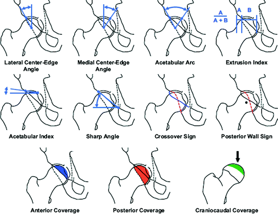

Fig. 2
The radiographic parameters quantifying acetabular geometry in terms of over- and under-coverage are shown. All of these parameters are assessable on plain radiographs. However, multiplanar imaging and modern software applications furthermore enable judgement in three-dimensions and aid in comprehending the complexity of the underlying disease. Moreover preoperative planning is largely enhanced. The goal of acetabular reorientation should be restoration or approximation of the normal values for these parameters. Reprinted with permission from Clin Orthop Relat Res (2015) 473:1234–1246
6 Traditional Planning of PAO
When first described in 1983, the planning possibilities for pelvic osteotomies were limited. Multiplanar imaging was just introduced and the almost unlimited access to these imaging modalities as available today was not the case in these times. The diagnosis of the underlying hip joint pathology, as well as the preoperative planning relied entirely on two-dimensional radiographs. Radiographic projections of choice were anteroposterior pelvis radiographs and for judgement in a second plane either axial, frog leg lateral, Dunn or false profile views of the affected hips. The examiner could then assess the hip joints by applying the measurements of the above-named classic parameters [32, 34] and estimate the amount of correction needed. Although still applied today, the difficulty with this planning method is to comprehend a complex three-dimensional problem on two-dimensional x-rays and derive a preoperative plan from these. Furthermore, it is even more challenging to realize the preoperative plan intraoperatively during acetabular reorientation. One means to estimate the amount of correction needed was the additional acquisition of abduction x-rays of the pelvis (Fig. 3). In the original work by Ganz et al. planning was described as follows:
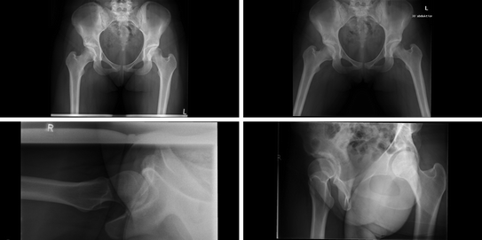
Roentgenographic analysis of the hip to be treated includes an anteroposterior (AP) view of the pelvis and a false profile (faux profil of Lequesne and deSeze), which is used to determine the anterior coverage of the femoral head. An additional AP view of the hip to be osteotomized, with the leg in abduction, has been found to be useful in demonstrating the optimal relationship between the femoral head and acetabulum. Preoperative planning is much more precise with a three-dimensional imaging technique derived from computed tomography (CT) data. It allows movement of femoral head cartilage relative to the cartilage of the acetabulum, thereby determining the real angular corrections of the acetabulum and, if needed, the proximal femur.

Fig. 3
A typical set of planning x-rays before periacetabular osteotomy is shown. The left upper image is a regular ap pelvis x-ray, the lower left and right images are axial, respectively false profile views of the hip joint. The upper right image is an abduction x-ray with both hip joints in 30° of abduction. In addition to the standard radiographs, the abduction view allows for estimation an increase in femoral head containment that might be achieved with the reorientation procedure
7 Intraoperative Verification of Reorientation
Intraoperatively, once the periacetabular osteotomies have been performed, the correct reorientation of the acetabulum is controlled with serial anteroposterior pelvic x-rays in analogy to preoperative planning. The above-mentioned parameters are re-assessed during this crucial step of the operation, while the acetabular fragment is temporarily secured with threaded Kirschner wires (Fig. 4). Once the desired position of the acetabulum has been achieved as verified by the intraoperative x-ray, the definitive fixation can then be performed with 3.5 mm cortical screws.
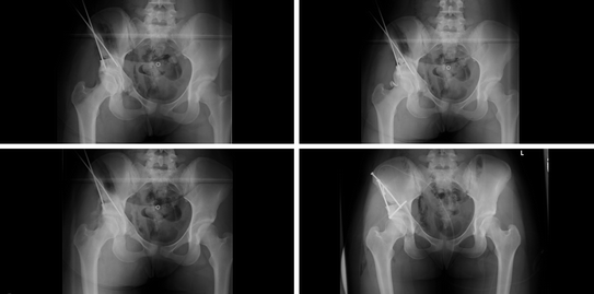

Fig. 4
Intra- and post-operative images of the same patient introduced for the planning x-rays are shown. In consecutive order from upper left to lower right, these images show how the acetabular reorientation is performed in a stepwise pattern. Once the periacetabular osteotomies have been performed, the acetabular fragment can be moved freely. According to the underlying pathology, the surgeon performs the correction. The fragment is then temporarily fixated using threaded Kirschner wires and intraoperative ap radiographs of the pelvis are obtained to control the orientation judged by the above-named parameters. This step can be repeated until the desired correction is achieved and the fragment can be definitely fixed by using 3.5 mm cortical screws (lower right image)
8 Assessment of Conventional X-rays Using Software Applications
With the advent of digital radiography and enhanced options of image processing, the methods for assessment of conventional x-rays and hence preoperative became more sophisticated. Analogous plain films have to be evaluated using rulers and markers, in order to measure the recognized radiographic parameters around the hip joint. Digital images—regardless the format—can be assessed using a computer. One of the things in common is the potential source of measurement error due to tilt and rotation of the pelvis during acquisition of the x-ray [27]. While correction on plain analogous films is not possible, one sophisticated application able to do on digital images has been introduced and validated. Hip2Norm is a software application that allows for measurement of the above-named radiographic parameters on digital pelvic x-rays, normalizing these x-rays for tilt and rotation. Validated against measurements based on CT scans, the method proved to be an accurate, reliable, consistent and reproducible application for assessment of these parameters on plain x-rays [33]. In more detail, the software allows the correction of the projected acetabular rim and associated important parameters for individual pelvic tilt and rotation. It uses two linear distances, which are derived from an ap pelvis x-ray and a subsequent one time lateral pelvis x-ray. The vertical distance between the sacrococcygeal joint and the superior border of the symphysis is then used to control for individual pelvic tilt, while the horizontal distance of the sacrococcygeal joint and the symphysis is used to control for rotation. The examiner can then use an interface to define certain anatomic landmarks on the ap pelvis x-ray (Fig. 5). The computer then calculates the above-named classic geometrical parameters of the hip joint and provides a result sheet with the raw data (Fig. 6) and the data corrected for individual tilt and rotation of the patient’s pelvis (Fig. 7). The potential of this software shows, how it can be used for more sophisticated preoperative planning of a PAO procedure. The examiner can assess the hip joint’s configuration more accurate and base the correction during the intervention on this assessment. Furthermore, the software can be used to assess the postoperative x-rays in order to quantify the achieved amount of correction.
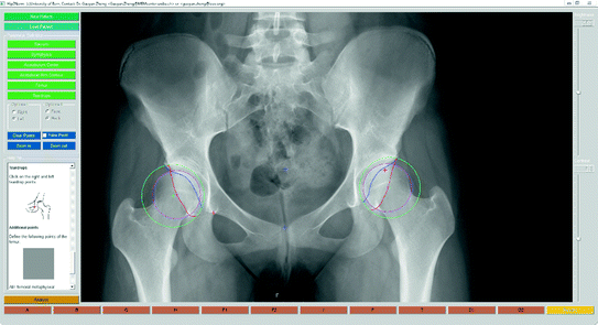
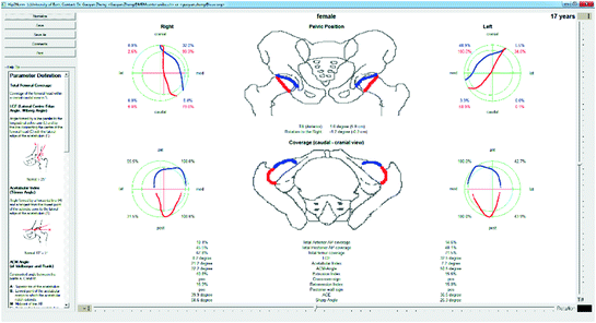
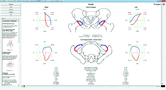

Fig. 5
The user interface of the software Hip2Norm is shown. Using an ap pelvis x-ray and a one time lateral x-ray of the patients’ pelvises, the surgeon can define a set of predefined anatomical landmarks. These will be used to calculate acetabular geometry in terms of the classic parameters

Fig. 6
The analysis report of the Hip2Norm software is shown. After input of the anatomical landmarks on the ap pelvis x-ray, the computer calculates classic parameters describing hip joint morphology. This analysis shows the data, which is not yet corrected for the individual tilt and rotation of the patient’s pelvis

Fig. 7
The analysis report of Hip2Norm of the same patient is shown, in this case now corrected for individual tilt and rotation. In order to achieve this correction, the software needs a one-time strict lateral x-ray of the patient’s pelvis. The algorithm then uses the vertical distance between the sacrococcygeal joint and the superior border of the symphysis to control for individual pelvic tilt, while the horizontal distance of the sacrococcygeal joint and the symphysis is used to control for rotation. Note the differences in the values between uncorrected (Fig. 6) and corrected analysis
9 Computer-Assisted Three-Dimensional Planning of Periacetabular Osteotomy
With enhanced multiplanar imaging methods, several authors have described methods of using the derived true 3D datasets for more accurate assessment of hip joint morphology and for planning of periacetabular osteotomies. Klaue et al. [12] already in 1988 published work on CT evaluation of coverage and congruency of the hip prior to osteotomy. In the absence of modern image segmentation software, the authors used the multiplanar slices of the CT scan to outline the femoral head and the facies lunata, as well as the cartilaginous acetabular surface. Afterwards, the resulting lines were backprojected to a 2D topographical map of the femur and acetabulum. Finally, intersections of those plotted maps could be defined as the coverage of the femoral head. Afterwards, the authors used 3D models of the patients’ femur and acetabulum and were able to perform rudimentary correction maneuvers in version, flexion/extension and rotation with subsequent estimation of improvement of coverage. In another study, Millis and Murphy [16] used reconstructed CT scans for quantifying femoral head containment through measuring classic parameter such as lateral, anterior, and posterior center edge angles in true three dimensions. In order to judge the relationship of the acetabular rim and the femur, the acetabulum itself was modeled as a hemisphere using latitude angles. By assessing the hip joint in three-dimensions, the authors derived important information for the amount correction of impending reorientation procedures of different kinds.
Stay updated, free articles. Join our Telegram channel

Full access? Get Clinical Tree


