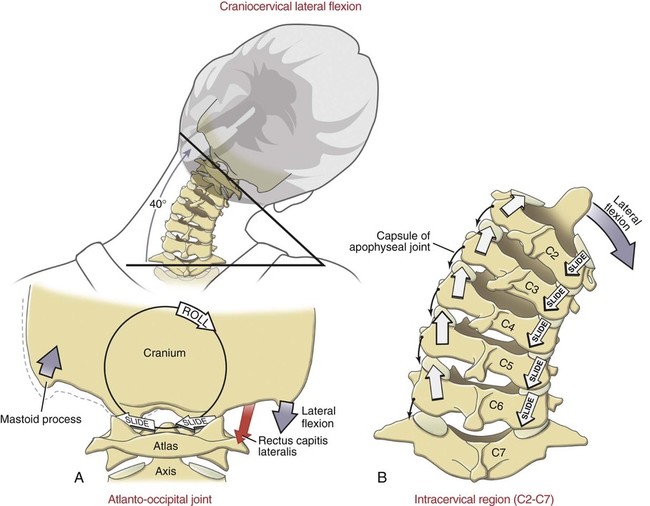
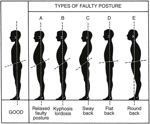
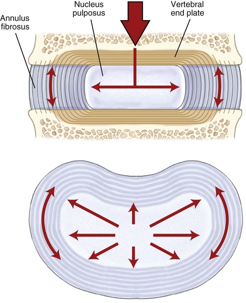
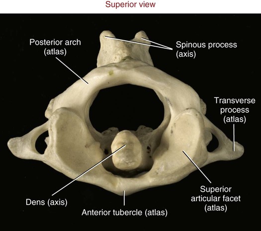
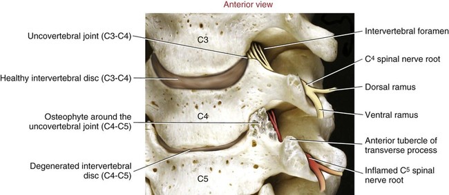
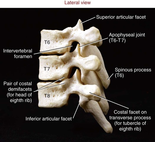
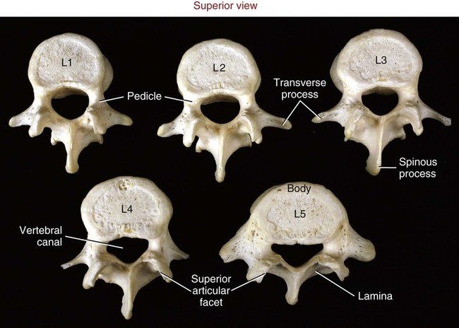
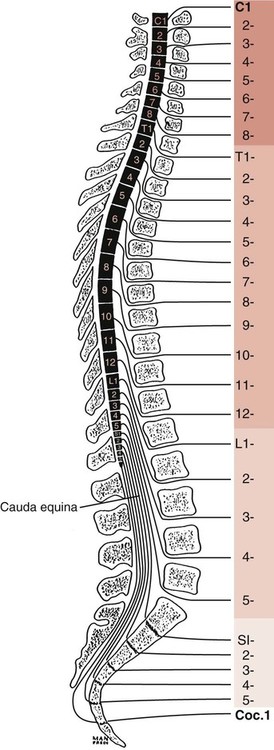
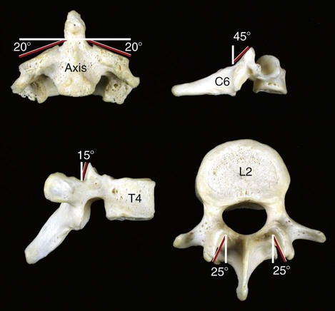
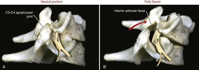
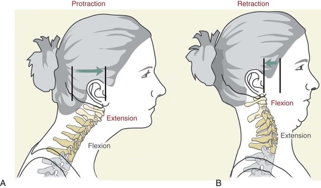
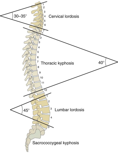
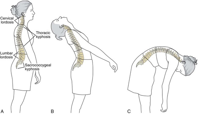
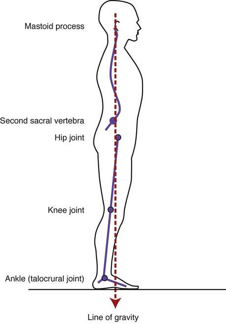
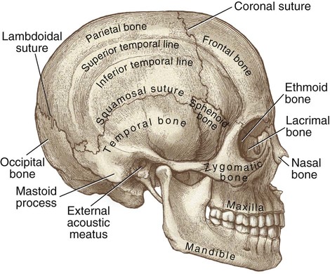
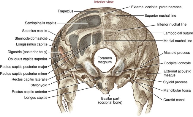
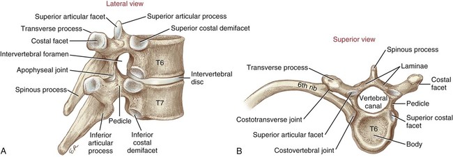
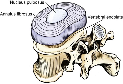
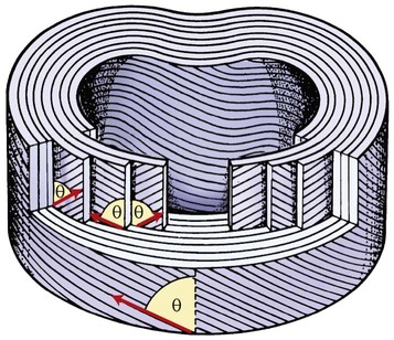
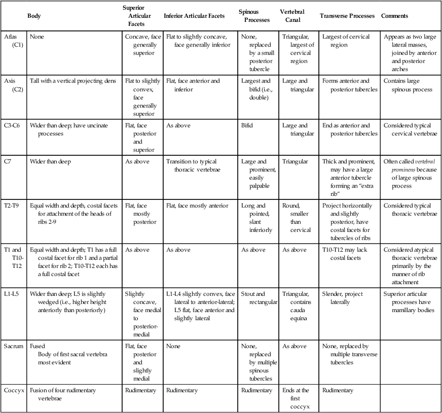
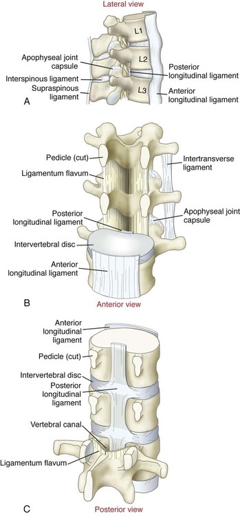
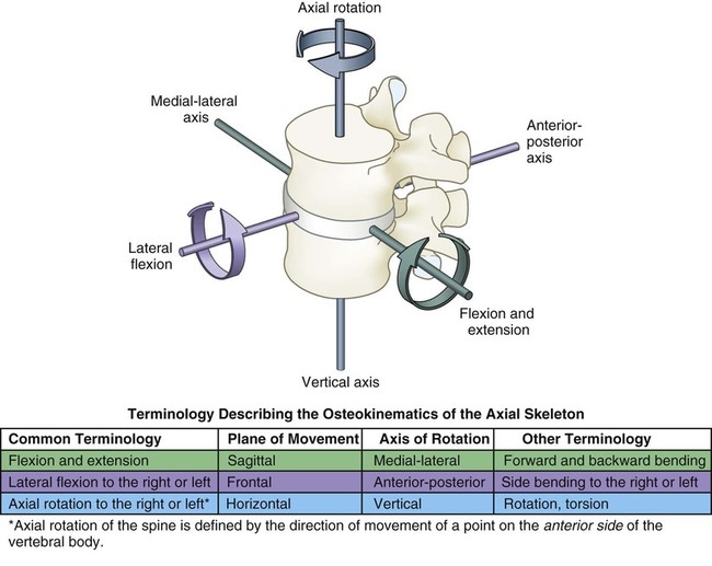
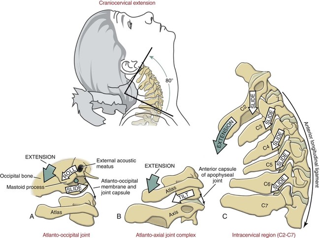
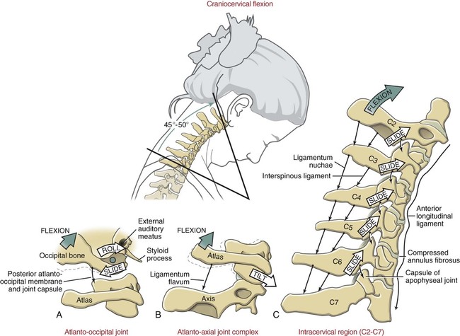
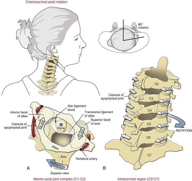
• Identify the normal curvatures of the vertebral column, and explain how these curves provide spinal stability. • Identify the bones and bony features of the vertebral column and cranium. • Describe the ligaments and soft tissues of the vertebral column and important features of an intervertebral disc. • Describe the unique features of the cervical, thoracic, lumbar, and sacral vertebrae. • Cite the normal ranges of motion allowed for flexion and extension, lateral flexion, and axial rotation at the craniocervical and thoracolumbar regions of the vertebral column. • Explain how the orientation of the facet joints helps determine the primary movements of the various regions of the vertebral column. • Describe the motions of the spine that decrease and increase the diameter of the intervertebral foramen. • Describe the effects of flexion, extension, and lateral flexion on the potential migration of the intervertebral disc. • Justify the actions of the muscles within the anterior and posterior craniocervical region of the vertebral column. • Justify the actions of the muscles within the anterior and posterior thoracolumbar region of the vertebral column. • Differentiate between segmental and gross stabilization of the vertebral column. • Describe the factors that contribute to safe and unsafe lifting techniques. The human vertebral column is composed of a set of natural curves, as is illustrated in Figure 8-1. These reciprocal curves are responsible for the normal resting, or neutral, posture of the spine. The cervical and lumbar regions display a natural lordosis, or slightly extended posture, in the sagittal plane. In contrast, the thoracic and sacrococcygeal regions exhibit a natural kyphosis, or slightly flexed, posture. The anterior concavity of the thoracic and sacral regions provides space for important vital organs within the chest and pelvis. The natural curvatures of the vertebral column are not fixed; they are dynamic and flexible to accommodate a wide variety of different postures and movements (Figure 8-2). For example, extension increases the lordosis of the cervical and lumbar regions but reduces the thoracic kyphosis (Figure 8-2, B). Flexion, in contrast, reduces the lordosis of the lumbar and cervical regions and accentuates the kyphotic curve of the thoracic region (Figure 8-2, C). Although highly variable, the line of gravity acting on a person with ideal posture passes through the mastoid process of the temporal bone, anterior to the second sacral vertebrae, slightly posterior to the hip, and slightly anterior to the knee and ankle (Figure 8-3). As indicated in Figure 8-3, the line of gravity courses just to the concave side of each vertebral region’s curvature. Consequently, in ideal posture, gravity produces a torque that helps maintain the optimal shape of each spinal curvature, allowing one to stand at ease with minimal muscular activation and minimal stress on surrounding connective tissues. These ideal biomechanics significantly reduce the energy of maintaining postures such as standing and sitting. Many persons exhibit poor posture as a result of muscular tightness or weakness, trauma, poor habit, body fat distribution, disease, or heredity. Figure 8-4 displays five commonly observed abnormal or “faulty” postures. Over time, these postures may significantly destabilize the spine, requiring compensatory strategies that alter normal motion of the trunk, the extremities, or the body as a whole. For example, the swayback posture illustrated in Figure 8-4, C, is often associated with significant tightness of the lumbar extensor muscles and excessive stretch (and potentially weakness) of the abdominal muscles. This posture can increase shear forces on the intervertebral discs and joints that interconnect the lumbar spine. Clinicians who treat people with back and neck pain often attempt to correct faulty postures as a primary component of the rehabilitation process. The cranium, or skull, is the bony encasement that protects the brain. Many of the bony features described herein serve as attachments for muscles and ligaments. Numerous other important features of the cranium are not described but are labeled in Figures 8-5 and 8-6. Literally meaning “large hole,” the foramen magnum is located at the base of the skull, providing a passage for the spinal cord to meet the brain (see Figure 8-6). The prominent occipital condyles project from the anterior-lateral margins of the foramen magnum. These convex structures articulate with the atlas (first cervical vertebrae), forming the atlanto-occipital joint. Just posterior to each ear are the large, palpable mastoid processes, which serve as the cranial attachment for numerous muscles of the head and neck, most notably the sternocleidomastoid. All vertebrae have several common features, many of which are evident upon examination of different views of a thoracic vertebra (Figure 8-7). The body of a vertebra is the large cylindrical mass of bone that serves as the primary weight-bearing structure throughout the vertebral column. The intervertebral disc is the thick fluid-filled ring of fibrocartilage that serves as a shock absorber throughout the vertebral column. The specific anatomy of intervertebral discs is covered in the next section. The interbody joint is formed by the junction of two vertebral bodies and the interposed intervertebral disc. Intervertebral discs play an extremely important role in absorbing and transmitting compression and shear forces throughout the spinal column. Each intervertebral disc is composed of three primary components: The nucleus pulposus, the annulus fibrosus, and the vertebral end plate (Figure 8-8). The nucleus pulposus is the gelatinous center of the disc. Composed of 70% to 90% water, the nucleus pulposus serves as a hydraulic shock absorber, dissipating and transferring forces between consecutive vertebrae. The annulus fibrosus is composed of 10 to 20 concentric rings of fibrocartilage that, in essence, encase the nucleus pulposus. As illustrated in Figure 8-9, the rings of fibrocartilage form a crisscross pattern that strengthens the walls of the annulus. When two vertebrae are compressed from the pressure of body weight or muscular forces, the nucleus pulposus is squeezed outward, producing tension within the annulus fibrosus (Figure 8-10). This tension stabilizes the spongy disc, converting it to a stable weight-bearing structure. The vertebral end plate connects the intervertebral disc to the vertebrae above and below and helps provide the disc with nutrition. Individual vertebrae are numbered by region in a cranial-to-sacral direction. For example, C3 indicates the third cervical vertebrae from the top of the cervical spine. T8 indicates the eighth thoracic vertebrae (from the top), L4 describes the fourth lumbar vertebrae, and so on (see Figure 8-21 on p. 189). Although all vertebrae have common anatomic characteristics, they also possess distinct features that reflect the unique function of a particular region. The following section, along with Table 8-1, highlights osteologic features that are specific to each region of the vertebral column. Osteologic Features of the Vertebral Column From Neumann DA: Kinesiology of the musculoskeletal system: foundations for physical rehabilitation, St Louis, 2002, Mosby, Table 9-4. The seven cervical vertebrae are the smallest and most mobile of all vertebrae, reflecting the wide range of motion available to the head and neck (Figure 8-11). The transverse processes of the cervical vertebrae possess transverse foramina (Figure 8-11, A), which serve as a protective passageway for the vertebral artery as it courses toward the brain. The small rectangular bodies of C3-C7 are bordered posteriorly-laterally by uncinate processes. The articulation of these hook-like uncinate processes with adjacent vertebrae forms the uncovertebral joints (see Figure 8-13), making this region of the cervical spine appear like a set of stackable shelves. Most of the spinous processes in the cervical region are bifid, or two-pronged, and provide attachments for muscles from both sides of the body. Observe that the apophyseal (facet) joints throughout C3-C7 are oriented like shingles on a sloped roof in a plane that is about 45 degrees between the horizontal and frontal planes (Figure 8-11, B). This orientation has an important impact on the kinematics of this region—a point that is revisited later in this chapter. The Greek god Atlas is said to have supported the weight of the world on his back. The first cervical vertebra is also called the atlas, reflecting its function in supporting the weight of the cranium. The atlas is essentially two large lateral masses connected by anterior and posterior arches (Figure 8-12). Two large concave superior facets sit on top of these lateral masses to accept the large convex occipital condyles, forming the atlanto-occipital joint. Other distinguishing features include large transverse processes—the largest in the cervical region. The axis derives its name from the large pointed projection of bone, called the dens, which literally functions as the vertical axis of rotation for rotary movements between the head and the upper cervical region (see Figure 8-12). The superior facets of the axis (C2) are relatively flat, matching the flattened inferior facets of the atlas. This conformation is well designed to allow the atlas (and head) to freely rotate in the horizontal plane over the axis, such as when the head is turned to the left or right. The bifid spinous process of C2 is broad and palpable (see Figure 8-12). The 12 thoracic vertebrae are characterized by their sharp, inferiorly projected spinous processes and large posterior, laterally projected transverse processes. The body and transverse processes of most thoracic vertebrae have costal facets for articulation with the posterior aspect of the ribs (Figure 8-14). The anterior portion of most ribs attaches either directly or indirectly to the sternum. Therefore, the ribs, thoracic vertebrae, and sternum define the volume of the thoracic cavity. Of note is that the apophyseal joints of the thoracic vertebrae are aligned nearly in the frontal plane. The lumbar vertebrae have massive, wide bodies, suitable for supporting the entire superimposed weight of the body (Figure 8-15). The spinous processes are broad and rectangular, connected to the body of the vertebrae through stout, thick laminae and pedicles. The facet joints of the upper lumbar region are oriented close to the sagittal plane but transition toward the frontal plane in the lower regions (L4 and L5) (Figure 8-15). The sacrum is a triangular bone that transmits the weight of the vertebral column to the pelvis. The wide flat sacral promontory (Figure 8-16) articulates with L5, forming the lumbosacral junction. The posterior or dorsal surface of the sacrum is convex and rough, reflecting the numerous ligamentous and muscular attachments. The sacral canal (Figure 8-16) houses and protects the cauda equina (peripheral nerves extending from the bottom end of the spinal cord). Four paired dorsal sacral foramina transmit the dorsal rami of sacral nerves. On the anterior or pelvic aspect of the sacrum, four paired ventral sacral foramina (Figure 8-17) transmit the ventral rami of spinal nerves that form much of the sacral plexus. Sometimes referred to as the tailbone, the coccyx is a small triangular bone consisting of four fused vertebrae (see Figure 8-17). The base of the coccyx articulates with the inferior sacrum, forming the sacrococcygeal joint. As with any other joint in the body, the joints of the spine are supported by ligaments that (1) prevent unwanted or excessive movements, and (2) protect underlying structures (Figure 8-18). Both functions are particularly important in the vertebral column because the soft and vulnerable spinal cord relies on the integrity of the vertebral column for protection. The primary supporting structures of the vertebral column are described in Table 8-2. Note that these supporting ligaments of the spine are similar to any other ligaments found in the body; they can become torn, weak, or overly shortened if held in a shortened range for a long period of time. As will be described later in this chapter, forces from activated muscle also play an essential role in stabilizing and protecting the vertebral column. Major Ligaments of the Vertebral Column From Neumann DA: Kinesiology of the musculoskeletal system: foundations for physical rehabilitation, St Louis, 2002, Mosby, Table 9-3. By convention, movement at any spinal region is defined by the direction of motion of a point on the anterior side of the vertebrae. For example, rotation to the right indicates that the anterior side (body) of the vertebrae is rotating to the right. This can be confusing because the more visible (and palpable) spinous process rotates to the left—in the opposite direction. Furthermore, movement occurs within a plane relative to an associated axis of rotation coursing through the vertebral body (Figure 8-20). The terms craniocervical region and neck are used interchangeably. Both terms refer to the combined set of three articulations: Atlanto-occipital joint, atlanto-axial joint, and intracervical region—referring to the cervical joints between C2 and C7. The craniocervical region is the most mobile area of the entire vertebral column. The individual joints within this region function in a highly coordinated manner to facilitate positioning of the head, which plays a large role in vision, hearing, hand-eye coordination, and equilibrium. Table 8-3 summarizes the average ranges of motion contributed by each area within the craniocervical region. Approximate Range of Motion for the Three Planes of Movement for the Joints of the Craniocervical Regions* *The horizontal and frontal plane motions are to one side only. Data are compiled from multiple sources (see text) and subject to large intersubject variations. From Neumann DA: Kinesiology of the musculoskeletal system: foundations for physical rehabilitation, ed 2, St Louis, 2010, Mosby, Table 9-7. Figure 8-21 illustrates an individual in full 80 degrees of craniocervical extension. Full craniocervical flexion of 45 to 50 degrees is pictured in Figure 8-23. About 25% of the total sagittal plane motion occurs through the combined motions of the atlanto-occipital and atlanto-axial joints; the remaining motion occurs across the intracervical (C2-C7) region. The atlanto-occipital joints are well designed to produce flexion and extension because the convex occipital condyles and corresponding concave facet surfaces of the atlas fit like rockers on a rocking chair: The occipital condyles roll backward during extension (see Figure 8-21, A) and forward during flexion (Figure 8-23, A). In accordance with the arthrokinematic rules described in Chapter 1, the roll and the slide occur in opposite directions. The atlanto-axial joint, although primarily designed for horizontal plane motion, allows about 10 degrees of extension and 5 degrees of flexion (Figures 8-21, B, and 8-23, B). Flexion and extension of the intracervical region (C2-C7) result in an arc of motion determined by the oblique plane of the cervical facet joints. As described earlier, these joints are oriented in a plane about 45 degrees between the horizontal and frontal planes. During extension, the inferior facets of the superior vertebra slide posteriorly and inferiorly—relative to the vertebra below it (Figure 8-21, C). The mechanics of flexion are the reverse of the mechanics of extension (Figure 8-23, C). Rotation of the head and neck in the horizontal plane is an important motion, integral to vision and hearing. As shown in Figure 8-24, the craniocervical region rotates about 90 degrees to each side, allowing nearly 180 degrees of rotational motion. With an additional 150 to 160 degrees of total horizontal plane motion of the eyes, the visual field approaches 360 degrees without moving the trunk. The atlanto-axial joint is responsible for about half of the rotation that occurs in the craniocervical region. The vertical dens and nearly horizontal superior facets of the axis (C2) allow the ring-shaped atlas (C1) to rotate freely and securely about 45 degrees in either direction (Figure 8-24, A). Note that the head does not rotate independently of the ring-shaped atlas. The deeply seated atlanto-occipital joint strongly resists rotation; rotation of the head therefore is the result of the atlas and the attached cranium rotating as a fixed unit relative to the axis (Figure 8-24, A). Rotation of C2-C7 is guided primarily by the oblique orientation of the facet joints. The combined motion of these joints allows about 45 degrees of rotation in either direction and is mechanically coupled with very slight amounts of lateral flexion secondary to the orientation of the facet joints (Figure 8-24, B). The arthrokinematic movements involved with rotation to the right are illustrated in Figure 8-24, B. The craniocervical region allows about 40 degrees of lateral flexion to each side. Although minimal, the atlanto-occipital joint contributes about 5 degrees of lateral flexion in either direction (Figure 8-25, A). Most of the motion occurs between C2 and C7. The arthrokinematic motion between C2 and C7 is illustrated in Figure 8-25, B. Once again, this motion is guided by the 45-degree incline of the facet joints. Because of the orientation of the facet surfaces, sight horizontal plane rotation is mechanically coupled with lateral flexion.
Structure and Function of the Vertebral Column
Normal Curvatures
Line of Gravity
Osteology
Cranium
Typical Vertebrae
Intervertebral Discs
Specifying Vertebrae and Intervertebral Discs
Comparison of Vertebrae at Different Regions
![]() Table 8-1
Table 8-1
Body
Superior Articular Facets
Inferior Articular Facets
Spinous Processes
Vertebral Canal
Transverse Processes
Comments
Atlas (C1)
None
Concave, face generally superior
Flat to slightly concave, face generally inferior
None, replaced by a small posterior tubercle
Triangular, largest of cervical region
Largest of cervical region
Appears as two large lateral masses, joined by anterior and posterior arches
Axis (C2)
Tall with a vertical projecting dens
Flat to slightly convex, face generally superior
Flat, face anterior and inferior
Largest and bifid (i.e., double)
Large and triangular
Forms anterior and posterior tubercles
Contains large spinous process
C3-C6
Wider than deep; have uncinate processes
Flat, face posterior and superior
As above
Bifid
Large and triangular
End as anterior and posterior tubercles
Considered typical cervical vertebrae
C7
Wider than deep
As above
Transition to typical thoracic vertebrae
Large and prominent, easily palpable
Triangular
Thick and prominent, may have a large anterior tubercle forming an “extra rib”
Often called vertebral prominens because of large spinous process
T2-T9
Equal width and depth, costal facets for attachment of the heads of ribs 2-9
Flat, face mostly posterior
Flat, face mostly anterior
Long and pointed, slant inferiorly
Round, smaller than cervical
Project horizontally and slightly posterior, have costal facets for tubercles of ribs
Considered typical thoracic vertebrae
T1 and T10-T12
Equal width and depth; T1 has a full costal facet for rib 1 and a partial facet for rib 2; T10-T12 each has a full costal facet
As above
As above
As above
As above
T10-T12 may lack costal facets
Considered atypical thoracic vertebrae primarily by the manner of rib attachment
L1-L5
Wider than deep; L5 is slightly wedged (i.e., higher height anteriorly than posteriorly)
Slightly concave, face medial to posterior-medial
L1-L4 slightly convex, face lateral to anterior-lateral; L5 flat, face anterior and slightly lateral
Stout and rectangular
Triangular, contains cauda equina
Slender, project laterally
Superior articular processes have mamillary bodies
Sacrum
Fused
Body of first sacral vertebra most evident
Flat, face posterior and slightly medial
None
None, replaced by multiple spinous tubercles
As above
None, replaced by multiple transverse tubercles
Coccyx
Fusion of four rudimentary vertebrae
Rudimentary
Rudimentary
Rudimentary
Ends at the first coccyx
Rudimentary
Cervical Vertebrae
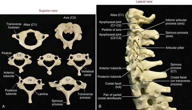
Typical Cervical Vertebrae (C3-C7)
Atlas (C1)
Axis (C2)
Thoracic Vertebrae
Lumbar Vertebrae
Sacrum
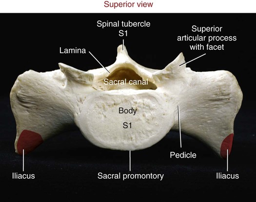
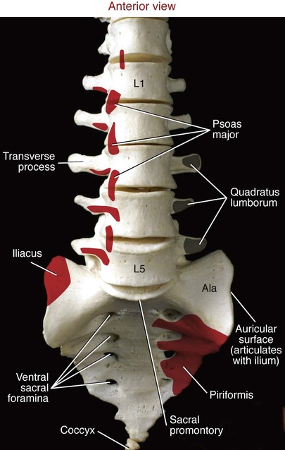
Coccyx
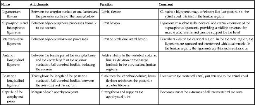
Supporting Structures of the Vertebral Column
![]() Table 8-2
Table 8-2
Name
Attachments
Function
Comment
Ligamentum flavum
Between the anterior surface of one lamina and the posterior surface of the lamina below
Limits flexion
Contains a high percentage of elastin; lies just posterior to the spinal cord; thickest in the lumbar region
Supraspinous and interspinous ligaments
Between adjacent spinous processes from C7 to the sacrum
Limit flexion
Ligamentum nuchae is the cervical and cranial extension of the supraspinous ligaments, providing a midline structure for muscle attachments and passive support for the head
Intertransverse ligaments
Between adjacent transverse processes
Limit contralateral lateral flexion
Few fibers exist in the cervical region. In the thoracic region, the ligaments are rounded and intertwined with local muscle. In the lumbar region, the ligaments are thin and membranous
Anterior longitudinal ligament
Between the basilar part of the occipital bone and the entire length of the anterior surfaces of all vertebral bodies, including the sacrum
Adds stability to the vertebral column; limits extension or excessive lordosis in the cervical and lumbar regions
Posterior longitudinal ligament
Throughout the length of the posterior surfaces of all vertebral bodies, between the axis (C2) and the sacrum
Stabilizes the vertebral column; limits flexion; reinforces the posterior annulus fibrosus
Lies within the vertebral canal, just anterior to the spinal cord
Capsule of the apophyseal joints
Margin of each apophyseal joint
Strengthens and supports the apophyseal joint
Becomes taut at the extremes of all intervertebral motions
Kinematics of the Vertebral Column
Craniocervical Region
![]() Table 8-3
Table 8-3
Joint or Region
Flexion and Extension (Sagittal Plane, Degrees)
Axial Rotation (Horizontal Plane, Degrees)
Lateral Flexion (Frontal Plane, Degrees)
Atlanto-occipital joint
Flexion: 5
Extension: 10
Total: 15
Negligible
About 5
Atlanto-axial joint complex
Flexion: 5
Extension: 10
Total: 15
35-40
Negligible
Intracervical region (C2-C7)
Flexion: 35-40
Extension: 55-60
Total: 90-100
30-35
30-35
Total across craniocervical region
Flexion: 45-50
Extension: 75-80
Total: 120-130
65-75
35-40

Flexion and Extension
Axial Rotation
Lateral Flexion
