Resurfacing Hip Arthroplasty
Techniques
Thomas P. Schmalzried
Key Points
• Obtaining adequate femoral and acetabular exposure is the key to accurate component insertion.
• Neck notching and vigorous component impaction predispose to femoral neck fracture.
• The role of proper acetabular component placement cannot be overemphasized.
Introduction
More than 10 years of experience with metal-metal resurfacing utilizing hybrid fixation (cemented femur and cementless socket) has been documented. Although implant technology and instrumentation will evolve, several technical principles have been established. Femoral neck fracture is the most common cause of early resurfacing failure. Neck notching and vigorous component impaction predispose to femoral neck fracture. Cobalt-chromium alloy monoblock resurfacing acetabular components osseointegrate somewhat less reliably than modular titanium alloy components.1 Acetabular lateral opening angles greater than 50 degrees, retroversion, or high combined anteversion is associated with increased wear, higher ion levels, and increased risk of revision.2–4
Preoperative Planning
Quality radiographs in multiple planes are helpful in assessing hip deformity and planning the resurfacing procedure. An anteroposterior (AP) pelvis with the beam centered on the pubis, a “frog” lateral, and Johnson’s or “shoot-through” lateral are recommended. It is helpful to appreciate the deformity pattern. At one end of the spectrum is the patient with anterior femoral acetabular impingement (FAI). These hips tend to be found in males (larger stature) and to have normal or reduced femoral valgus (higher femoral offset); the head tends to be relatively posterior and inferior on the neck, and low combined anteversion is seen frequently. At the other end of the spectrum is the dysplastic hip. These hips usually are seen in females (smaller stature) and have increased femoral valgus (reduced femoral offset); the head tends to be relatively centered on the neck, and combined anteversion (femoral plus acetabular anteversion) is increased. The deformity pattern has implications for both femoral and acetabular component positioning. Johnson’s lateral is useful for assessing anterior and posterior aspects of the hip and the potential for postoperative FAI (Fig. 64-1).
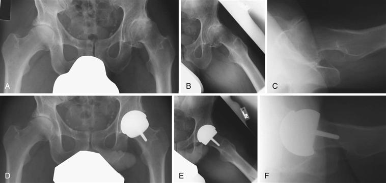
Figure 64-1 Radiographic evaluation. This patient has more of a dysplastic deformity pattern. A, Low anteroposterior (AP) pelvis centered on the pubis. Note that an external rotation position of the femur results in an apparent increase in neck valgus. B, Modified frog lateral. C, Johnson’s shoot-through lateral. Note the calcified anterior labrum/osteophyte. D, Postoperative AP pelvis. Note the low lateral opening angle of the socket and the valgus orientation of the femoral component. E, Postoperative modified frog lateral. The femoral component is slightly anteverted. F, Postoperative shoot-through lateral demonstrating socket anteversion and removal of the calcified anterior labrum/osteophyte flush with the anterior rim of the socket.
The goals of templating are to get an estimate of component size and to visualize the orientation of the components relative to the patient’s bony anatomy. The diameter of the femoral neck determines the smallest component size that can be used; the acetabulum determines the largest size possible. The outer diameter of the resurfacing acetabular component should be within 2 mm of what would be used for a total hip in that acetabulum.5 Acetabular component positioning goals are not different from those of total hip replacement. Some medialization is desirable with a lateral opening angle in the 40- to 45-degree range. On the femoral side, relative varus component positioning should be avoided. The longitudinal position of the femoral component can be adjusted for limb length. Because the socket is medialized and the femoral offset is unchanged by resurfacing, the offset of the hip tends to be decreased by resurfacing5 (Fig. 64-2).
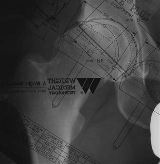
Figure 64-2 Templating. The acetabular component template is positioned first using the teardrop as a medial reference. The lateral opening angle target is 40 to 45 degrees. The femoral component template is aligned with the neck axis. The neck diameter determines the smallest possible femoral component size.
Exposure
Resurfacing can be performed through several approaches. Regardless of the surgical approach, the principles of exposure for resurfacing are similar. Goals include a circumferential view of the femoral head/neck during femoral preparation and a circumferential view of the acetabulum during acetabular preparation (Fig. 64-3). The major difference in exposure compared with total hip replacement is the capsular release (resection). Capsular release is needed to mobilize the proximal femur to (1) elevate the head out of the wound for femoral preparation and (2) translate the proximal femur for acetabular exposure. The extent of the release can be variable, depending on the degree of stiffness. Care must be taken in retractor placement and in performance of the capsular release not to stray from the joint and risk injury to adjacent nerves and vessels and the iliopsoas tendon. Partial excision of a hypertrophic capsule can facilitate acetabular exposure. The author tries not to disrupt any soft tissue (e.g., capsule, synovium) on the femoral neck.
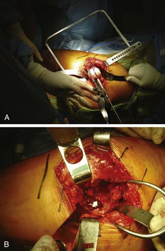
Figure 64-3 A, Femoral exposure and guide pin placement. For this posterior approach on a left hip, the patient’s leg is to the left. The ipsilateral knee is flexed to about 90 degrees, and the foot is pointed toward the ceiling (hip internally rotated). A flat retractor under the femoral neck elevates the head and protects the posterior tissues. Anterior and posterior cobra retractors facilitate a 360-degree view around the head and neck. A guide pin has been placed along the neck axis, and the orientation/clearance is being checked with a stylus. B, Acetabular exposure. Same patient, left hip, posterior approach, the leg is to the left. The femoral head has been prepared and retracted anterior beneath the abductor. The surgeon has a 360-degree view of the socket.
Related posts:

Stay updated, free articles. Join our Telegram channel

Full access? Get Clinical Tree


