Fig. 1
The camera augmented mobile C-arm. The mobile C-arm is extended by an optical camera and mirror construction
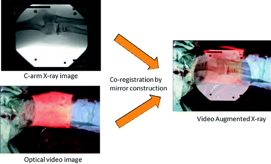
Fig. 2
CamC implicitly registers X-ray images (upper-left) and video images (lower-left) to provide video augmented X-ray imaging (right). The picture depicts an elbow fracture reduction surgery
2.1 CamC System Components
The first clinical CamC (Fig. 3) was built by affixing a Flea2 camera (Point Grey Research Inc., Vancouver, BC, Canada) and mirror construction to a mobile Powermobile isocentric C-arm (Siemens Healthcare, Erlangen, Germany). The system comprises three monitors: the common C-arm monitor showing the conventional fluoroscopic image, the CamC monitor displaying the video image augmented by fluoroscopy, and a touch screen display providing the user-interface. A simple alpha blending method is used to visualize the co-registered X-ray and video images. The surgical crew can operate the CamC system like any standard mobile C-arm. A two-level phantom is used to align the camera and X-ray source. The phantom’s bottom level has five X-ray visible xed markers and the top level has 5 movable small rings. The calibration consists of aligning the top rings and bottom markers in both X-ray and video images and then a homography is calculated for image overlay [11].
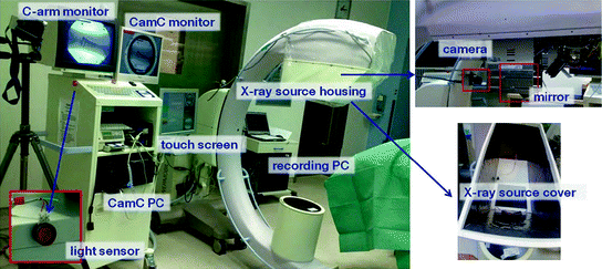

Fig. 3
The system components of CamC used during patient surgeries
Misalignments between the treated patient anatomy in the X-ray and video images could happen due to patient movement. To visually inform surgeons about misalignments, the initial positions of a marker visible in the X-ray image are drawn as green quadrilaterals and their positions in the current video image are drawn as red quadrilaterals. Moreover, a gradient color bar is shown on the right side of the video images, whose length indicates the pixel-difference between the marker initial and current positions (Fig. 4).
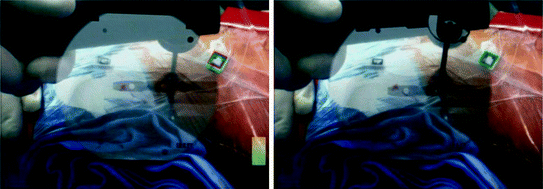

Fig. 4
Visual square marker tracking to inform surgeons about a possible misalignment between the X-ray and video image
2.2 CamC Patient Study
Forty-three patients were treated successfully with CamC support between July 2009 and March 2010 at the Klinikum der Universität München, Klinik für Allgemeine, Unfall-, Hand- und Plastische Chirurgie, Germany. This is the first time that a medical augmented reality technology was used consistently in real orthopaedic surgeries worldwide. Once an X-ray image is acquired, the surgical procedure may be continued solely under the visualization of video without additional radiation exposure. The patient study resulted in identifying the following surgical tasks which directly benefit from the medical AR imaging of CamC: X-ray positioning, incision, and instrument guidance.
First, X-ray positioning consists in iteratively moving the C-arm over the patient and is completed once the C-arm is correctly positioned to show the treated anatomy. Although this task seems intuitive, it may take several C-arm positions to acquire the correct X-ray image. The CamC overlay resolves this task by showcasing a semi-transparent grey circle within the video image. This augmentation allows the medical staff to efficiently position the C-arm above the anatomy to be treated. Figure 5-left demonstrates X-ray positioning for visualizing a fractured distal radius. Secondly, after acquiring an X-ray image showing the bone anatomy or implants, it is often required to open the skin in order to access bone anatomies or implants. The CamC overlay is used to plan the correct incision, placing the scalpel exactly above the entry point of interest. An example of this is seen in Fig. 5-center, where the entry point localization during an interlocking procedure is facilitated by positioning the scalpel on the nail hole. Lastly, many orthopaedic surgeries require the precise alignment of surgical instruments with the correct axis. This is usually achieved by first aligning the tip of the instrument with the entry point and then orienting the instrument to be aligned with the axis by acquiring many X-ray images. Using the CamC video guidance, this process is simplified. As an example, K-wires are often used for temporary fixation of bone fragments or for temporary immobilization of a joint during surgery. With the CamC system, the direction of a linear K-wire relative to the bone can be intuitively anticipated from the overlay image showing the projected direction of the K-wire and bone in a common image frame (Fig. 5-right).


Fig. 5
Left The CamC video augmentation can play the role of an aiming circle to position the C-arm optimally to acquire the desired X-ray image. Center Incision above the implant hole is facilitated using the CamC overlay between X-ray and video. Right Positioning of surgical instruments, such as a K-wire, relative to distal radius fractures becomes intuitive by visualizing the X-ray and video overlay
2.3 Example CamC Orthopaedic Applications
Multi-view AR: The CamC provides AR visualization and guidance in two-dimensional space and no depth control is possible. Thus, the system is limited to applications where depth is not a factor such as in the interlocking of intramedullary nailing procedure. To resolve this limitation, Traub et al. [12] developed a multi-view opto-Xray system that provides visualization capable of depth control during surgery (Fig. 6). In addition to the original video camera mounted to the C-arm gantry, a second camera is attached orthogonal to the gantry such that its view is aligned with the X-ray image taken at a 90° orbital angle to the current C-arm position. After a one time calibration of the newly attached video camera, the surgical instrument tip position can be augmented within a lateral X-ray image while the surgeon navigates the procedure using an anterior–posterior view. The feasibility of the system has been validated through cadaver studies [12].
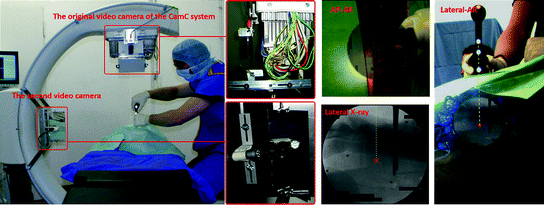

Fig. 6
Left The multi-view opto-X-ray system. Center The AP view of the video augmented X-ray image for axis control with the lateral X-ray image. Right The lateral view of the video augmented X-ray image for depth control
Panoramic X-ray imaging: X-ray images generated by mobile C-arms have a limited field of view. Hence, one X-ray image may not capture the entire bone anatomy. Acquiring several individual X-rays to capture the entire bone in separate images only gives a vague impression of the relative position and orientation of the bone segments. This often compromises the quality of surgeries. Panoramic X-ray images that could show the entire bone as a whole would be helpful particularly for long bone surgeries. Existing methods in state-of-art have a common limitation which is parallax errors [13, 14]. A new method based on CamC was developed to generate parallax-free panoramic X-ray images during surgery by enabling the mobile C-arm to rotate around its X-ray source center (Fig. 7) relative to the patient table [15]. Rotating the mobile C-arm around its X-ray source center is impractical and sometimes impossible due to the mechanical design of mobile C-arms. To ensure that the C-arm motion is a relative pure rotation around its X-ray source center, the table is moved to compensate for the translational part of the motion based on C-arm pose estimation. C-arm pose estimation methods, like the one proposed by [16–20], use visible markers or radiographic fiducials during X-ray imaging. Such methods are not suitable for positioning of the table since continuous X-ray exposure is required, and therefore a large amount of radiation is inevitable. The CamC is a logical alternative for pose estimation since it contains a video camera. Moving the table and maneuvering the C-arm to reach a relative pure rotation of the X-ray source suffers from the complexity of the user interaction. Therefore, it is preferable for surgeons to specify a target position of X-ray images in a panorama frame and to be guided by the system on how to move the C-arm and the table as a kinematic unit. An integrated kinematic chain of the C-arm and the table with its closed-form inverse kinematics was developed by Wang et al. [21]. The technique could be employed to determine C-arm joint movements and table translations needed for acquiring an optimal X-ray image defined by its image position in a panorama frame. Given an X-ray image position within the panorama, the required C-arm pose is first automatically computed, and then the necessary joint movements and table translations from the closed-form inverse kinematics are solved. The surgeon keeps defining targets within the panorama frame until he/she are content with the final parallax-free panoramic image. The final image was used to determine, for example, the mechanical axis deviation in a cadaver leg study [22].
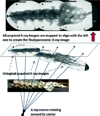

Fig. 7
Parallax-free X-ray image stitching method. A parallax-free panoramic X-ray image of a plastic lumbar and sacrum is generated by stitching three X-ray images acquired by the X-ray source undergoing pure rotations
Distal locking of intramedullary nails: Intramedullary nailing is the surgical procedure mostly used in fracture reduction of the tibial and femoral shafts. Following successful insertion of the nail into the medullary canal, it must be fixed by inserting screws through its proximal and distal locking holes. Prior to distal locking of the nail, surgeons must position the C-arm device and patient leg in such a way that the nail holes appear as circles in the X-ray image. This is considered a ‘trial and error’ process, is time consuming and requires many X-ray shots. Londei et al. [23] proposed an augmented reality application that visually depicts to the surgeon two ‘augmented’ circles, their centers lying on the axis of the nail hole, making it visible in space. After an initial X-ray image acquisition, real-time video guidance using CamC allows the surgeon to superimpose the ‘augmented’ circles by moving the patient leg; the resulting X-ray showing nail holes appearing as circles. Following this, distal locking of the nail hole can be completed. Authors in [24, 25] designed a radiation-free guide to enable surgeons to complete the interlocking of intramedullary nailing procedure without a significant number of X-ray acquisitions. The radiation-free guide is detected by the CamC camera and its tip is measured in real-time and displayed to the surgeon in both the X-ray and video images. A cannula consisting of two branches with markers are affixed to the radiolucent drill. Computer vision algorithms are developed that exploit cross ratio properties in order to estimate the tip-position of the novel radiation-free instrument allowing the surgeon to visualize and guide distal locking (Fig. 8). A recent study presented the complete pipeline of distal locking using augmented reality [26].
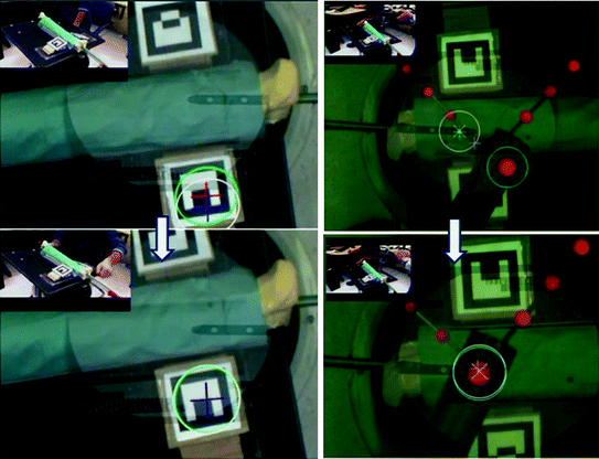

Fig. 8
Left Augmented circles visualization for the down-the-beam positioning of the nail, and right the augmented drill and target location for distal locking
Multi-modal visualization: It is increasingly difficult to rapidly recognize and differentiate anatomy and objects in alpha-blended images as is the case with the CamC system. The surgeon’s depth perception is altered since: (i) the X-ray anatomy appears floating on top of the scene in the optical image, (ii) surgeon hands and surgical instruments occlude the visualization, and (iii) there is no correct ordering between anatomy and objects in the fused images. With these issues in mind, we observe that all pixels in X-ray and optical images do not have the same importance and contribution to the final blending (e.g. the background is not important compared to the surgical instruments). This reflection suggests extracting only relevant-based data according to pixels belonging to background, instruments, and surgeon hands [27]. The labeling of the surgical scene by a precise segmentation and differentiation of its different parts allows a relevant blending respecting the desired ordering of structures. A few attempts have been endeavored, such as in [28]. In these early works, a Naive Bayes classification approach based on color and radiodensity is applied to recognize the different objects in X-ray and video images. Depending on the pair of pixels it belongs to, each pixel is associated to a mixing value to create a relevant-based fused image. While authors showed promising results, recognizing each object on their color distribution is very challenging and not robust to changes in illumination.
Pauly et al. [29] introduced a surgical scene labeling paradigm based on machine learning using the CamC system. In their application, the depth is a useful hint for the segmentation and ordering of hands and instruments with respect to patient anatomy since the surgeon performs the procedure on the patient. Thus, their visualization paradigm is founded on segmentation consisting in modeling the background via depth data. They perform in parallel color image segmentation via the state-of-art Random Forests. To refine the segmentation method, they use the GrabCut algorithm. Lastly, the authors combine the background modeling and color segmentation in order to identify the objects of interests in the color images and achieve successfully ordering of structures (Fig. 9).
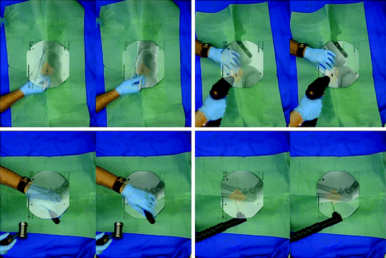

Fig. 9
Four clinical examples comparing the traditional alpha-blending visualization technique to the relevance-based fused images
C-arm positioning via DRRs: Dressel et al. [30] propose to guide C-arm positioning using artificial fluoroscopy based on the CamC system. This is achieved by computing digitally reconstructed radiographs (DRRs) from preoperative CT data or cone-beam CT. An initial pose between the patient and the C-arm is computed by rigid 2D/3D registration. After the initial pose estimation, a spatial transformation between the patient and the C-arm is obtained from the video camera affixed to the CamC. Using this information, it is able to generate DRRs and simulate fluoroscopic images. For positioning tasks, this solution appears to match conventional fluoroscopy; however simulating the images from the CT data in real time as the C-arm is moved is performed radiation-free.
Stay updated, free articles. Join our Telegram channel

Full access? Get Clinical Tree


