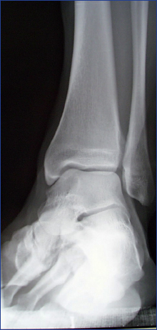
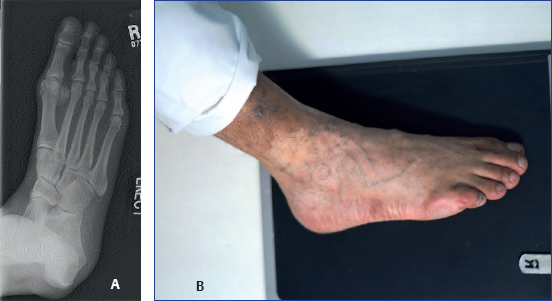
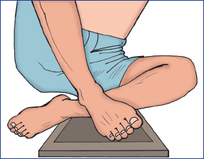
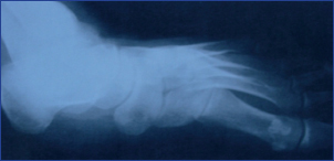
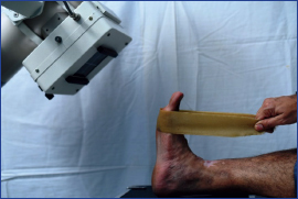
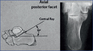
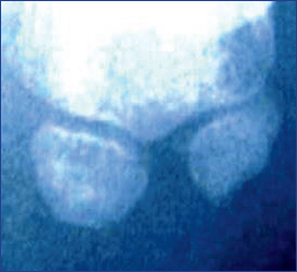
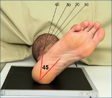
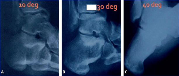
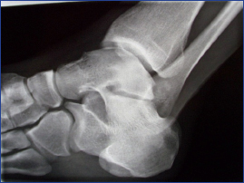
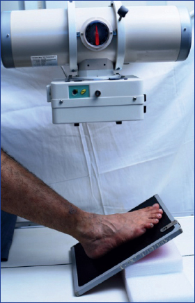
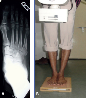
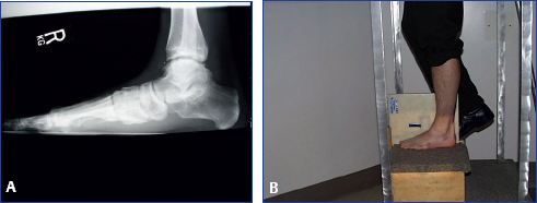
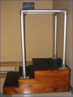
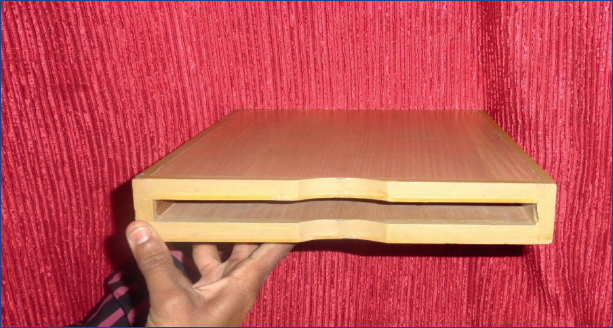
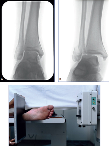
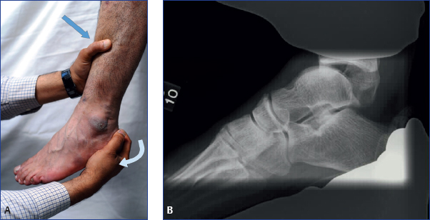
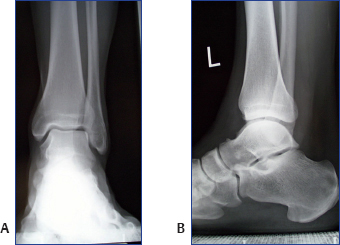
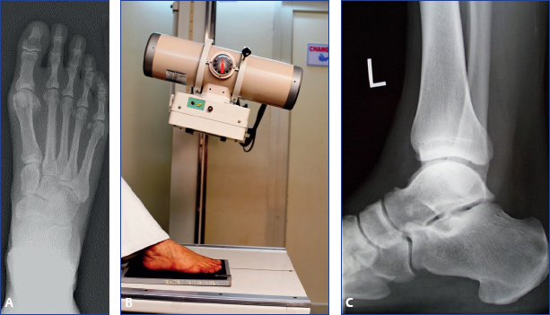
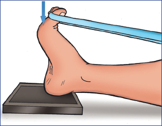
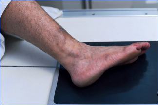
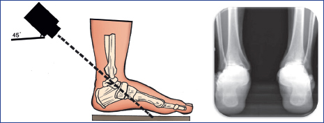
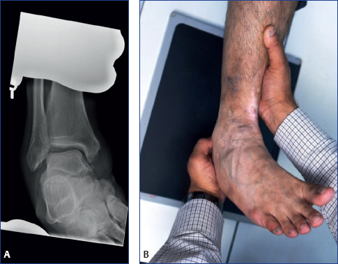
Chapter 2 Radiological examination of foot and ankle is not the substitute to clinical examination! The following points need to be carefully observed and analyzed for correct evaluation of the radiographs: ♦ Position and alignment of bones ♦ Spacing or overlap of bones ♦ Continuity or breech in continuity of bones ♦ Outline of the articular surfaces ♦ Quality of bones ♦ Angles, lines, and radiological signs In total, there are four types of radiographs. These are listed in Box 2.1. Box 2.1 Types of radiographs ♦ Routine radiographs ♦ Specialized radiographs ♦ Weight-bearing radiographs ♦ Stress radiographs These include a series of ankle and foot X-rays. ♦ Ankle series X-rays • Anteroposterior (AP) (Fig. 2.1A) • Lateral (LAT) (Fig. 2.1B) • Oblique (mortise) views: Mortise view is 15-degree internal rotation view, which clearly shows ankle mortise in its true plane. Mortise view eliminates overlap of fibula over tibia so that position and alignment of both bones can be evaluated (Fig. 2.2). Fig. 2.2 Mortise view of ankle. ♦ Foot series X-rays • Dorsoplantar (AP) (Fig. 2.3A, B) • Lateral (LAT) (Fig. 2.3C) • Oblique (internal oblique or lateral oblique) views: This view shows lateral column of foot, cuboid, and fourth and fifth metatarsals (Fig. 2.4A, B). Fig. 2.4 (A and B) (A) Internal oblique or lateral oblique view of foot, and (B) method of obtaining internal oblique or lateral oblique view of foot. ♦ Medial oblique or external oblique view of foot: This view shows the medial column of foot, navicular, medial cuneiform, first metatarsal and its articulations (Figs. 2.5 and 2.6). Fig. 2.5 Positioning for taking external oblique or medial oblique view of foot. Fig. 2.6 External oblique or medial oblique view of foot. ♦ Harris axial view of heel: This view shows calcaneus and subtalar joint (Figs. 2.7 and 2.8). Fig. 2.7 Method of taking Harris axial view. Fig. 2.8 Harris axial view of heel. ♦ Sesamoid view: This view is needed for diagnosing the problems of sesamoids (Figs. 2.9 and 2.10). Fig. 2.10 Sesamoid view of foot. ♦ Broden’s views: These views are taken with 10, 20, 30, and 40 degrees cranial angulation of an X-ray beam focused at the tip of the fibula, with ankle rotated 45 degrees internally. Excellent view of posterior subtalar joint given by these views helps in intraoperative monitoring of calcaneus fracture reduction and assessment of postoperative fusion status of subtalar joint (Figs. 2.11 and 2.12). Fig. 2.11 Ankle and foot positioning for obtaining Broden’s view. Fig. 2.12 Broden’s view at 10°, 30°, and 40° rotation. ♦ Canale and Kelly’s view: This view is taken with foot plantar flexed and pronated to 15 degrees and it delineates medial column along the talus. This view is used for assessing the amount of comminution and displacement of fracture neck talus (Figs. 2.13 and 2.14). Fig. 2.14 Canale and Kelly’s view. ♦ Comparative views: Because of extensive overlap and typical articulating pattern of foot and ankle bones, comparative views are needed. Important information regarding the length of bones, spaces between bones, and pattern of articulation of bones is gained from comparative views. Comparative views are commonly used for planning as well as intraoperative analysis of ankle, midfoot, and Lisfranc injuries. ♦ Midfoot X-ray projection: It is mandatory to keep the X-ray beam perpendicular to the midfoot and not to the floor for precise projection of midfoot. This can be done using a special stand or by tilting the X-ray tube (Fig. 2.15). Fig. 2.15 Method of midfoot X-ray projection. Radiographs of the weight-bearing foot and ankle can demonstrate the foot and ankle in a more functional situation and may provide insight into the relationship among the soft tissues, bones, and the joints under physiologic loads. Some important points of consideration are as follows: ♦ Majority of problems in foot and ankle are noticed or aggravated during weight bearing or walking. This justifies the study and analysis of bones and joints during weight-bearing posture. Any alterations seen on weight bearing X-ray views will give information about the integrity of bony and ligamentous structures. ♦ AP, LAT, and oblique weight-bearing views of ankle: These views give an idea about the deformation on weight bearing and are useful for defining the stages of flat foot and defining the integrity of deltoid ligament. ♦ AP, LAT, and oblique weight-bearing views of foot: These views are important to define subtle injuries of the midfoot, stages of flat foot, and deformation in neuropathic foot. Measurements of various angles for treating hallux valgus are also done through these views (Figs. 2.16 and 2.17). Fig. 2.16 (A and B) (A) Weight-bearing AP image of foot and (B) method of obtaining weight bearing view of foot. Fig. 2.17 (A and B) (A) Weight-bearing lateral view of foot and (B) method of obtaining weight-bearing lateral view of foot. ♦ Saltzman view: It is a tangential weight-bearing postero-anterior view of the hindfoot and leg, demonstrating weight-bearing relationship of the hindfoot with the leg (Fig. 2.18). ♦ Comparison of non–weight-bearing X-ray views with weight-bearing X-ray views is a must. ♦ Interpretation notes on weight-bearing X-rays focuses on the following points: • Change in position and alignment of bones • Opening of bony spaces • Angulation of bones • Articular space • Angles, lines, and radiological signs ♦ A special stand with steps is required to take weight-bearing view of the ankle (Fig. 2.19). A 1-inch-deep slot on the top step of this stand is used for inserting the X-ray cassette. The stand needs to be wide enough (2–2.5 feet) for the patient to stand comfortably. The height of the step should not be more than 6 inches. There should be a holding rail attached to the X-ray stand for support. Fig. 2.19 Stand for obtaining weight-bearing AP, oblique, and lateral views of ankle. ♦ The patient stands in various positions on the step of the stand in front of the cassette, and the X-ray beam is projected from the front. ♦ The same stand can be used for taking weight-bearing lateral view of the foot where the patient stands on the step and the cassette is inserted in the slot. ♦ For weight-bearing X-rays of foot, a special wooden box is needed where a slot for X-ray cassette is provided (Fig. 2.20). Fig. 2.20 Stand for putting X-ray cassette for obtaining weight-bearing AP and oblique views of foot. ♦ The patient stands on the wooden box, and the beam is centered on the foot in different positions. ♦ Plain radiography has the following limitations: • Interobserver variations • Variations of exposure • Variations due to distance ♦ Stress radiography is the gold standard for analyzing integrity of the capsuleligamentous structures. Stress radiography is used for the diagnosis and evaluation of trauma as well as disorders of ankle and midfoot. ♦ In painful conditions, stress radiography can be done after injecting local anesthetic in the area of pain. ♦ Gravity stress view: is taken through cross-table projection of an externally rotated foot and ankle, with the affected side lying upward. This view would show widening of the medial space and would help to diagnose syndesmotic injuries (Fig. 2.21). Fig. 2.21 (A-C) (A and B) Opening up of ankle on gravity stress view of ankle, and (C) positioning for gravity stress view. ♦ Talar tilt stress view: helps in manipulation of the talus in inversion and evaluation of opening of ankle joint laterally. This view is used to assess lateral ligament insufficiency. View is taken by holding talus and tibia. Comparative views may also be required (Fig. 2.22). ♦ Anterior drawer stress view: assesses the manipulation of the stabilized foot against leg dorsal or plantar wards. This view is useful to assess ankle joint’s instability. Lower limb is suspended from the edge of table and the ankle lies in gravity-assisted plantar flexion, while the foot is either pushed or pulled against a stabilized tibia (Fig. 2.23). Fig. 2.23 (A and B) Anterior drawer stress view showing instability and the method of taking this view.
Radiology in Foot and Ankle
Interpretation of Radiographs
Routine Radiographs
Specialized Radiographs
Weight-Bearing Radiographs
How to Take Weight-Bearing Radiographs?
Stress Radiographs
Related posts:


Stay updated, free articles. Join our Telegram channel

Full access? Get Clinical Tree


