Radiographic Evaluation of the Hip
Stephen Duncan
John C. Carlisle
John C. Clohisy
Background
As our understanding of the biomechanics of hip function has improved, the approach to management of the painful hip has undergone considerable change (1,2). Disorders such as developmental hip dysplasia (DDH) and femoroacetabular impingement (FAI) have been more clearly identified as contributors to progressive labral and cartilage wear (1,2,3,4,5). Likewise, as outlined in previous chapters, our ability to identify intra-articular pathology of the hip has progressed, both from the standpoint of patient history, clinical examination, and radiographic work-up. Surgical interventions for the painful hip continue to be refined (6,7,8,9), and our ability to identify patients along the spectrum of disease continues to improve (10,11,12,13,14,15).
Nevertheless, because disease patterns have such a wide variability, the process of making an accurate radiographic diagnosis remains challenging. Providers must have standardized radiographic views, as well as a standardized approach to plain radiographic, CT and MRI interpretation that can serve as a foundation for accurate diagnosis, disease classification, and treatment planning.
Many different radiographic measurements have been described as indicators of structural abnormalities in the hip. In this chapter, we summarize our recommendations regarding radiographic imaging techniques and present an approach to image interpretation.
Radiographic Techniques
In the initial evaluation of any patient presenting with hip pain, the evaluation should include a radiographic evaluation of the hip. Standard conventional radiographic imaging for the young adult hip involves obtaining an anteroposterior (AP) pelvic view at the very minimum. Additional radiographic views to help understand the deformity causing the hip pathology include the following: false-profile view (16), cross-table lateral view (7), 45- or 90-degree Dunn view (17), and frog-leg lateral view (18). Each radiographic view provides information regarding the osseous structural morphology of the acetabulum and proximal femur (Table 12.1).
For proper interpretation of the pelvic and hip radiographs, correct positioning of the patient along with a standardized and accurate radiographic technique needs to be fulfilled. To improve the diagnostic accuracy of the hip measurements, the following section will review the proper patient positioning and radiographic technique to obtain adequate and reliable pelvic and hip radiographs.
Anteroposterior Pelvic View
The AP pelvic view should be obtained with the patient in the supine position with the legs internally rotated 15 degrees to compensate for femoral anteversion and allow for accurate assessment of the femoral offset and neck-shaft angle (17). The distance between the radiographic detector and the beam should be 120 cm and oriented perpendicular to the table. The beam should also be centered over the midpoint between a line connecting the anterosuperior iliac spines and the superior border of the pubic symphysis (Fig. 12.1A,B) (19,20). The appearance of acetabular morphology can vary widely depending on the tilt and rotation of the pelvis and thus parameters have been set to provide a reference for standardization. Neutral pelvic rotation is defined as the tip of the coccyx being in line with the midpoint of the superior border of the pubic symphysis with symmetrical appearance of the obturator foramen and iliac wings (4). Acceptable pelvic tilt has been further defined based on the patient’s gender and is evaluated by measuring the distance between the sacrococcygeal junction and the superior border of the pubic symphysis. For males, this distance is 3.2 cm, and in females, is 4.7 cm (19). However, the sacrococcygeal junction can be difficult to interpret and thus the tip of the coccyx can be used as another reference point when measuring to the superior border of the pubic symphysis, using a range of 1 to 3 cm for males and 2 to 5 cm for females (Fig. 12.2).
False-Profile View
The false-profile view is taken with the patient standing. The ipsilateral foot is placed parallel to the detector and the distance between the detector and the beam is 1 m. The pelvis is rotated 25 degrees toward the contralateral hip, making a 65-degree angle between the detector and the pelvis (Fig. 12.3) (16). An acceptable false profile in terms of the amount of pelvic rotation can be determined by measuring the distance
between the two femoral heads, which should be two-thirds the diameter of the affected femoral head (16).
between the two femoral heads, which should be two-thirds the diameter of the affected femoral head (16).
Table 12.1 Summary of Radiographic Views and the Parameters Used for Evaluation of the Hip | ||||||||||||||||||||||||||||
|---|---|---|---|---|---|---|---|---|---|---|---|---|---|---|---|---|---|---|---|---|---|---|---|---|---|---|---|---|
| ||||||||||||||||||||||||||||
Cross-Table Lateral View
The cross-table lateral view is taken with the patient in the supine position. The affected hip is internally rotated 15 degrees to profile the anterior femoral head/neck junction. The contralateral hip and knee is flexed 90 degrees respectively to allow for the radiograph to be obtained. The detector is positioned at 45 degrees in relation to the affected hip. The beam is directed toward the affected hip, perpendicular to the detector to obtain this view (Fig. 12.4). For patients with an elevated BMI, the use of filters can be used to reduce scatter and improve exposure.
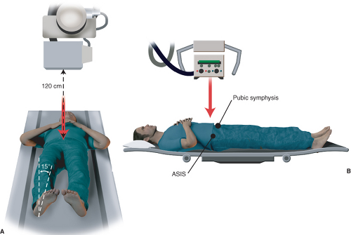 Figure 12.1. AP pelvis radiographic technique. A: The beam-to-detector distance with 15-degree internal rotation of the bilateral lower extremities. B: The beam needs to be centered over the midpoint between the ASIS and the superior border of the pubic symphysis. |
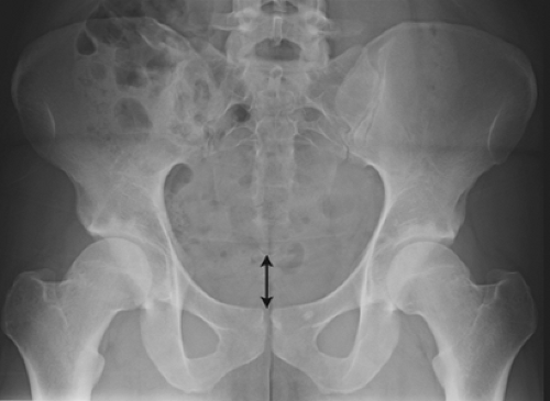 Figure 12.2. AP pelvic radiograph. The obturator foramen, iliac wing profile, and acetabular teardrops should be symmetric in appearance. The distance between the pubic symphysis and sacrococcygeal junction should be 1 to 3 cm in males and 2 to 5 cm in females. |
45- or 90-Degree Dunn View
The 45- or 90-degree Dunn view is obtained to profile the anterolateral femoral head/neck junction. With the patient in the supine position, the affected hip is flexed to either 45 degrees or 90 degrees, abducted 20 degrees, with neutral rotation of the leg. Similar to obtaining an AP pelvic radiograph, the beam is oriented perpendicular to patient at a point in between the anterior iliac spine and the superior border of the pubic symphysis with the detector-to-beam distance of 40 in (Fig. 12.5) (21).
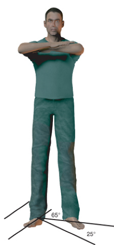 Figure 12.3. False-profile radiographic technique. The ipsilateral foot is positioned parallel to the detector with the pelvis rotated back toward the contralateral hip 25 degrees, making a 65-degree angle between the detector and the pelvis. The beam is oriented perpendicular to the detector. |
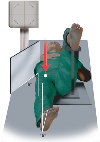 Figure 12.4. Cross-table lateral radiographic technique. The contralateral hip and knee are flexed to 90 degrees, whereas the affected hip is internally rotated to 15 degrees. The detector is positioned 45 degrees in relation to the hip and the beam, then oriented perpendicular to the detector. |
Frog-Leg Lateral View
The frog-leg lateral view is obtained with the patient in the supine position and provides information regarding the osseous morphology of the anterior femoral head/neck junction. With the affected hip abducted 45 degrees and the ipsilateral knee flexed 30 to 40 degrees, the ipsilateral heel is placed on the medial aspect of the contralateral knee. The detector is placed under the patient and the beam is centered perpendicular to the hip with the beam located at the midpoint between the anterior superior iliac spine and the superior border of the pubic symphysis at a detector-to-beam distance of 90 cm (Fig. 12.6).
Review and Interpretation of the Radiographic Images
Although obtaining a single radiographic view provides information regarding the hip, the information is limited to one plane. Using a combination of various radiographic views can help to provide a better understanding of the
global hip deformity in multiple planes. Each radiographic view provides different details pertaining to the acetabulum or the femur and has been outlined in Table 12.1. The following section will provide an in-depth description and interpretation of the radiographic views.
global hip deformity in multiple planes. Each radiographic view provides different details pertaining to the acetabulum or the femur and has been outlined in Table 12.1. The following section will provide an in-depth description and interpretation of the radiographic views.
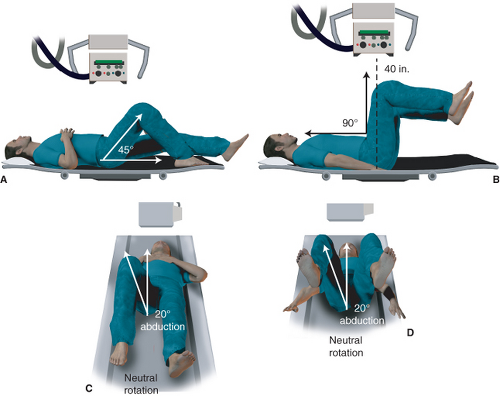 Figure 12.5. A–D: 45- and 90-degree Dunn radiographic technique. A and B: The technique to obtain the 45-degree Dunn view. With the hip flexed 45 degrees, abduction of 20 degrees, and neutral rotation, the beam is centered over the midpoint between the ASIS and the superior border of the pubic symphysis. B and D: The technique to obtain the 90-degree Dunn view. Similar to the method to obtain the 45-degree Dunn view, the hip is just flexed to 90 degrees. |
Ap Pelvis—Acetabular Radiographic Measures
The AP pelvic radiograph can provide information regarding both the acetabulum and femoral osseous morphology. On the acetabular side, the acetabular inclination, or Tönnis angle, can be measured to get an appreciation of the inclination of the weight-bearing portion of the acetabulum (Fig. 12.7). To obtain this measurement, a line is drawn connecting the ischial tuberosities or the teardrops to correct for pelvic obliquity (Line 1); a second line is drawn parallel to this line, intersecting through the inferomedial portion of the acetabular sourcil (Line 2). A third line is then made connecting the superolateral portion of the sourcil and the previously determined inferomedial sourcil (Line 3). The angle made between Lines 2 and 3 represents the acetabular inclination. Normative values are from 0 to 10 degrees with values less than 0 degree and greater than 10 degrees to be considered decreased and increased, respectively (21). In patients with values less than 0 degree, they are considered to be at risk for pincer FAI. For those patients with values greater than 10 degrees, they are potentially at risk for structural instability of the hip consistent with acetabular dysplasia (21).
Another measure to help assess for acetabular coverage of the femoral head involves the lateral center edge angle (LCEA) (Fig. 12.8) (22). Similar to the method for obtaining the acetabular inclination angle, the LCEA is obtained by first making a line connecting the ischial tuberosities or teardrops to correct for pelvic obliquity (Line 1). The center of the femoral head is then determined and a line perpendicular to Line 1 is made through the center of the femoral head (Line 2). A third line is then made connecting the superolateral portion of the acetabular sourcil and the center of the femoral head (Line 3). The angle formed by Lines 2 and 3 comprises the LCEA. There is debate regarding the range of normal values, but values less than 20 to 25 degrees are associated with acetabular dysplasia and values greater than 39 degrees are more consistent with possible pincer FAI (21).
To help determine if the patient has structural instability or has more acetabular overcoverage, the acetabular depth can be examined. The terms coxa profunda and acetabular protrusio are often used to describe the acetabular depth
radiographically. Coxa profunda
 Etiology of Hip Osteoarthritis
Measurement of Treatment Outcomes in the Young Patient with a Hip Disorder
Hip Arthroscopy Anatomy and Access to the Central Compartment
Chiari and Salvage Osteotomy for the Treatment of Symptomatic Acetabular Dysplasia
FAI: Extra-articular Bony Impingement
Treatment of Slipped Capital Femoral Epiphysis Deformities in Skeletally Mature Patients
Etiology of Hip Osteoarthritis
Measurement of Treatment Outcomes in the Young Patient with a Hip Disorder
Hip Arthroscopy Anatomy and Access to the Central Compartment
Chiari and Salvage Osteotomy for the Treatment of Symptomatic Acetabular Dysplasia
FAI: Extra-articular Bony Impingement
Treatment of Slipped Capital Femoral Epiphysis Deformities in Skeletally Mature Patients


radiographically. Coxa profunda
Related posts:
Etiology of Hip Osteoarthritis
Measurement of Treatment Outcomes in the Young Patient with a Hip Disorder
Hip Arthroscopy Anatomy and Access to the Central Compartment
Chiari and Salvage Osteotomy for the Treatment of Symptomatic Acetabular Dysplasia
FAI: Extra-articular Bony Impingement
Treatment of Slipped Capital Femoral Epiphysis Deformities in Skeletally Mature Patients
Stay updated, free articles. Join our Telegram channel
Full access? Get Clinical Tree
