Chapter 111 Posterior Cruciate Ligament–Substituting Total Knee Arthroplasty
Posterior cruciate substitution in total knee arthroplasty gathered momentum and popularity as the pioneering surgeons and design teams improved on their prototypes. Today, surgeons that prefer this principle and technique over cruciate retention believe that the anterior and posterior cruciate ligaments (ACL, PCL) are histologically abnormal and therefore compromised in arthritic knees.4,16,37 Furthermore, these surgeons believe that it is difficult to balance the PCL appropriately while maintaining its functional integrity and ability to accomplish near-normal femoral rollback.7
Evolution of Posterior Cruciate Ligament–Substituting Knee Arthroplasty
The Insall Group
The next significant advancement was achieved with the original total condylar prosthesis which was cruciate-sacrificing, not PCL-substituting. It was a semiconstrained, nonlinked, cemented design that involved excising both cruciate ligaments. First implanted in 1974, this cobalt-chrome femoral component had a symmetrical anterior flange and groove, two symmetrical condyles in the coronal plane, and a smaller radius of curvature posteriorly in the sagittal plane. The tibial component was a single piece of high-density polyethylene with biconcave articular surfaces, offering some stability.50 It was fully conforming in extension and less conforming in flexion to allow for more rotation and gliding of the femur. The small intercondylar eminence helped prevent translation movement, and the 35- × 12.5-mm tibial peg helped achieve fixation. The patella was a dome-shaped, central peg, high-density polyethylene design.
Complete cruciate ligament excision accomplished greater exposure and allowed for easier correction of fixed deformities. Without an intact ACL and PCL, the knee design relied on the congruity of the articular surfaces and integrity and balance of the collateral ligaments for stability. With well-balanced flexion and extension gaps, the collateral ligaments will tighten as the femoral component translates anteriorly, up the conforming tibial well, preventing dislocation. This concept, designed with the input of engineer Peter Walker and surgeons John Insall and Chitranjan Ranawat, was termed the uphill principle. The femoral component was intended to articulate centrally on the tibial component surface, with no rollback built into the design. This original total condylar knee proved to be a durable, sound design,31 but not without problems. Patients rarely achieved more than 90 degrees of flexion and, on occasion, the tibia would subluxate if the flexion gap was not adequately balanced, especially descending stairs. Such issues could potentially be resolved with a new prosthetic design that spared or substituted for the PCL.
Insall-Burstein I Posterior-Stabilized Prosthesis
To address the posterior subluxation and instability that would sometimes occur with the total condylar prosthesis, a central tibial post was added. This modification, however, proved to be an imperfect solution, as the specifics of the design and the hyperextension stop led to tibial edge loading and loosening.64 In 1976, Al Burstein joined John Insall at the Hospital for Special Surgery where they combined their experience, insight, and innovation to develop a posterior-stabilized knee that would substitute for the PCL, allow for complete correction of deformity, reproduce femoral rollback, improve flexion stability, and increase knee flexion.
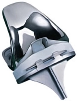
The first-generation Insall-Burstein prosthesis (IB I) was first implanted in 1978. The tibiofemoral contact point was shifted from a more central location to a more posterior point,32 resulting in a greater distance or hill to climb before the femur subluxates anteriorly. An intercondylar femoral cam was added to the design to replicate femoral rollback. It engaged the tibial post at approximately 70 degrees of flexion and, as the cam climbed the post, the tibiofemoral contact point shifted more posteriorly until approximately 115 degrees of flexion. These features, along with the increased conformity and 3-degree posterior slope of the all-polyethylene tibial component, helped the IB I achieve great success and durability.
Insall-Burstein II Posterior-Stabilized Prosthesis
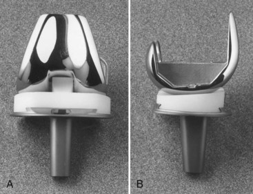
Additional changes were made to enhance femoral rollback, thereby improving flexion. Reports of component dislocation arose, especially in knees with preoperative valgus alignment or those that achieved a high degree of postoperative flexion. Consequently, additional modifications of the tibial insert included positioning the tibial post more anteriorly and increasing its height. This posterior-substituting design proved to be a functionally sound concept that performed well for more than a decade before it evolved further (Fig. 111-1).
NexGen Legacy
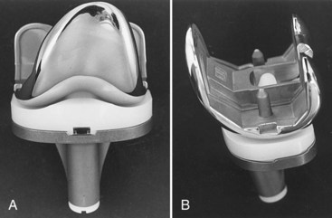
An expanded array of instruments became available with the NexGen Legacy prosthesis. These include epicondylar instruments to assist with femoral component rotation, anterior and posterior referencing size guides, and instruments to prepare the femur and tibia using a milling technique instead of the traditional cutting blocks and oscillating saw (Fig. 111-2).
NexGen Legacy High-Flexion and Gender-Optimized Implants
The increased desire by patients to pursue activities associated with greater degrees of knee flexion, as well as acknowledgment of the important cultural requirements in certain Asian populations, have driven the development high-flexion knee prostheses. These implants are designed to exceed 140 to 150 degrees of flexion compared with the 120 degrees permitted by traditional designs. To accommodate higher flexion, these design modifications include enhanced posterior condylar geometry of the femoral component, which improves contact areas in high flexion, thereby reducing the risk of polyethylene wear.6 In addition, modifications to the anterior aspect of the tibial polyethylene insert were made to reduce the potential for extensor mechanism impingement in high flexion. Finally the cam-post design of posterior-stabilizing (PS) variants was optimized to reduce the risk of dislocation in high flexion. To date, studies of high-flexion total knee replacement (TKR) prostheses have provided little data to support the theoretical advantages attributed to the optimized designs. In a recent meta-analysis, Ghandi and associates25 have noted that high flexion designs were associated with improved ROM compared with traditional implants, but offered no clinical benefits. Meneghini and coworkers52 have confirmed the lack of any functional benefit with flexion more than 125 degrees after TKR.
An example of a high-flexion design is the Zimmer NexGen Flex-Fixed PS implant, a modification of the NexGen legacy prosthesis. Studies of the NexGen Flex-Fixed PS implant are inconclusive. Kim and colleagues36 have reported on a prospective randomized study of 50 patients who underwent simultaneous bilateral TKR with a standard fixed-bearing Zimmer NexGen LPS knee prosthesis on one side and a high-flexion, fixed-bearing NexGen LPS-Flex knee prosthesis on the opposite side. The Knee Society and Hospital for Special Surgery (HSS) scores were not significantly different for either knee, either pre- or postoperatively. Moreover, there were no statistically significant differences in range of motion (ROM) at any time point pre- or postoperatively; at final follow-up, the standard prosthesis had a mean ROM of 135.8 degrees (range, 105 to 150 degrees) versus a mean of 135.8 degrees for the high-flexion prosthesis. A similar study was published by Nutton and associates.56 They compared patients who had been randomized to receive a standard or high-flexion version of the Zimmer NexGen LPS fixed-bearing design. Again, no significant differences in outcomes or knee flexion were noted between the two groups of patients.
Shortly after the development of high-flexion designs, increased acknowledgment of the anthropomorphic variation that exists among humans of different genders, races, and ethnic origins led to the introduction of gender-optimized components.26 These gender-specific components included modifications of the mediolateral to anteroposterior ratio of the femoral components, as well as to the orientation and thickness of the trochlear groove and anterior flange. An example of a gender-specific implant is the Zimmer Gender Solutions NexGen High Flex LPS prosthesis. This implant is a further modification of the NexGen Legacy. Results examining the use of gender-optimized devices remain controversial. Although radiographic and anatomic studies have demonstrated the gender bias of standard implants toward white male anatomy, little data exist to date to support that this bias has adversely affected clinical outcomes in white females or patients of other races.49
Other Current Posterior Cruciate Ligament–Substituting Implants
PFC Sigma
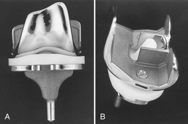
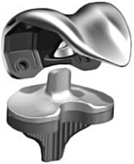
The versatile tibial tray was designed to accept a PCL-retaining, PCL-supplementing, or PCL-substituting polyethylene insert of varying thicknesses. In addition, the tray can be augmented with wedges, blocks, and stems if bone loss or poor bone quality dictates. More recently, a tibial rotating platform design was released. The goals of this concept are improvement in rotational biomechanics (20 degrees of supported internal and external rotation in deep flexion), reduction of backside wear, and lower peak stresses on the condyles because of tibiofemoral self-alignment (Fig. 111-3).
Genesis II
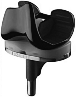
Stability of the Genesis II PCL-substituting knee depends on both the component’s articular geometry and the spine-cam interaction. The implants are designed to articulate freely through the first 60 degrees of flexion, with stability dependent on the surface geometry and soft tissue balance. Spine-cam engagement occurs at 60 to 70 degrees of knee flexion (Fig. 111-4).
Journey
In this effort to reproduce more anatomic knee motion, there are 5 degrees of screw-home designed in the Journey articulation as the knee comes to full extension. With progressive flexion, the forces of the extensor mechanism on the femur and the convex shape of the lateral tibial plateau yield external axial rotation of the femur, posterior femoral translation and rollback, and a slight medial pivot (Fig. 111-5).
Vanguard
The Vanguard system provides a spectrum of constraint from the standard PS insert, to the PS+, to the Super Stabilized Knee (SSK), to the SSK Constrained. These different polyethylene inserts allow for varying degrees of rotation, post height, and varus-valgus constraint (Fig. 111-6).
Triathlon
The Stryker Triathlon total knee arthroplasty system (Stryker Orthopaedics, Mahwah, NJ) was designed with the common goals of improved motion, increased flexion, greater sizing options, and minimization of wear. The femoral component radius of curvature was centered at the transepicondylar axis and designed to be more anatomic between 10 and 110 degrees. The central edges of the posterior condyles were tapered and the articular surface of the polyethylene was precisely machined to allow for approximately 20 degrees of tibiofemoral rotation. An anthropometric study was used to optimize the tibial and femoral sizing options. A 7-degree flexion cut was built into the anterior flange so that the femoral component could be downsized when necessary, with a reduced chance of femoral notching. The tibial component was designed with a central inset island to improve the ease of insertion and stability of the polyethylene component. This feature, along with the surface geometry mentioned earlier, aim to minimize micromotion and backside wear (Fig. 111-7).
Surgical Technique
The primary objectives of total knee arthroplasty are to relieve pain, improve function, correct deformity, and minimize the need for reoperation. The basic surgical technique for implanting PCL-substituting prostheses has been well documented.30,32 The intraoperative goal is a well-aligned, well-fixed prosthesis with coronal balance, an equal flexion and extension gap, and constant collateral ligament stability throughout the full range of motion. The postoperative mechanical axis is to be in the central portion of the knee. This will result in load sharing equally by the medial and the lateral compartments to minimize polyethylene wear and improve longevity.
As implant sizes expanded and instrumentation improved, Insall advocated a modified gap technique combining aspects of both measured resection and the gap technique of TKA.70 Tensors used to balance the collateral ligaments and align the knee were replaced with more sophisticated intramedullary instrumentation and spacer blocks. However, despite evolution of the technique and instrumentation, the basic concepts of the posterior-stabilized knee remain virtually unchanged.
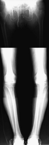
The modern surgical technique begins with thorough preoperative planning. AP, lateral, and Merchant view radiographs are obtained. Templating for size is performed with traditional templates or with a digital templating system. A hip to ankle full-length radiograph provides additional critical information (Fig. 111-8). This includes the preoperative anatomic and mechanical axis, preoperative deformity, presence of hardware from prior surgery, and status of the ipsilateral hip. Ensuring that there is nothing to preclude the use of intramedullary instrumentation will help avoid intraoperative surprises. The surgeon may choose the angle of distal femoral resection from the measured difference between the anatomic and mechanical axis of the femur (Fig. 111-9). Other surgeons prefer using 6 degrees for varus knees and 5 degrees for valgus knees or patients with larger thighs. Finally, a line is drawn perpendicular to the mechanical axis of the tibia, noting the estimated amount of bone to be resected from the medial and lateral aspects of the tibia.
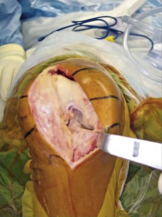
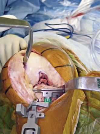
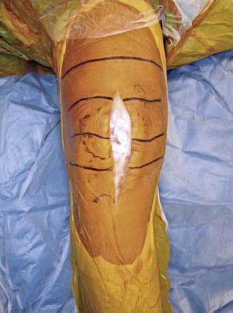
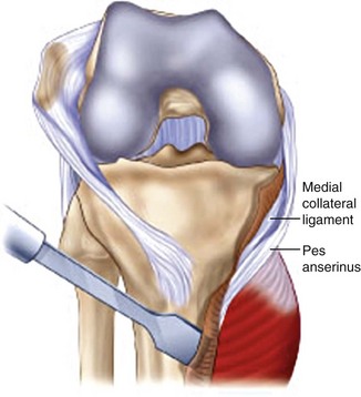
The knee is exposed with a straight anterior skin incision extending from the medial aspect of the tibial tubercle to two fingerbreadths proximal to the superior patellar pole (Fig. 111-10). Full-thickness subcutaneous flaps are developed, and 30 mL of 1% lidocaine with epinephrine is injected along the planned arthrotomy site to reduce intraoperative blood loss. A straight medial parapatellar capsular incision is used for the arthrotomy. A portion of the fat pad and genu articularis is excised to improve exposure. The periosteum of the proximal medial tibia is raised in a continuous layer off the tibia. Caution is used to avoid excessive medial dissection in the valgus knee. Laterally, a small cuff of periosteum is raised in continuity with the patellar ligament to provide some protection against tibial tubercle avulsion. The knee is assessed for a coronal fixed deformity. In the varus knee with a fixed deformity, a medial release may be performed at this point using the  -inch straight osteotome to elevate the superficial and deep fibers of the medial collateral ligament in continuity35 (Fig. 111-11). The knee is flexed and the patella is allowed to subluxate laterally (Fig. 111-12). Routine patellar eversion is not necessary.65
With the knee in the flexed position, the ACL is transected off the tibia surface. The tibia is now subluxed anteriorly. It is sometimes necessary, especially on varus knees, to continue the release of the structures off the posteromedial aspect of the tibia, including a portion of the semimembranosus, to allow adequate tibial subluxation.35
After adequate exposure has been achieved, attention is turned to the bone cuts. Proceeding with the tibial cut opens the flexion and extension gaps and further facilitates exposure. The tibia may be cut with an extramedullary or intramedullary guide system, depending on the surgeon’s preference and the knee anatomy. More frequently, an extramedullary guide is used during primary total knee arthroplasty (Fig. 111-13). The ideal cut is 90 degrees to the mechanical axis of the tibia, with a slight posterior slope in the anteroposterior plane. A skim cut is performed on the side with more severe wear and only 5 to 9 mm of bone is removed from the normal side. This is extremely important in patients with preoperative valgus deformity or obese females. In these patients, not only will excessive bone resection place the tibial component in a weaker cancellous bone bed, but it can lead to run way instability, requiring large polyethylene inserts or increased constraint. Additional tibial bone can easily be removed at a later stage of the procedure if the extension and flexion gaps are found to be too tight following the necessary ligament releases.
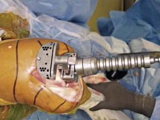
Attention is then turned to the femur. A small intramedullary hole is made to gain access to the femoral canal. This hole should be slightly (3 to 5 mm) medial to the center of the femoral groove to allow easy drilling of the intramedullary portion of the femur. The entry point can be more accurately determined using full-length radiographs and noting the point of intersection between the mechanical and anatomic axes of the femur. Because of concern regarding physiologic changes associated with intramedullary instrumentation, the hole is routinely vented by overdrilling the hole with a step drill and using a fluted intramedullary rod.21 This helps reduce intramedullary pressure during the placement of subsequent intramedullary guides. The femoral alignment guide is then inserted into this intramedullary channel. It should be set for the proper side and valgus angle (frequently 5 or 6 degrees) as determined by preoperative radiographs (Fig. 111-14).
For most knees, the standard cutting block is attached to the intramedullary femoral alignment guide before its insertion in the femoral canal. Most flexion contractures can be managed with standard bone cuts and soft tissue releases. However, for knees with a significant preoperative flexion deformity (>30 degrees), it may be beneficial to resect an additional 3 mm of distal femoral bone initially.66 This can be accomplished by removal of the standard cutting block, which will allow for this additional distal bone resection. At this point, the femoral alignment guide is inserted into the intramedullary canal. Although this step does not set the final rotation of the femoral component, it is useful to place the guide carefully to achieve reasonable rotation of the distal femoral cut. The epicondylar axis can be used to aid in optimizing this rotation. Desired rotation is neutral to slight external rotation to ensure that the posterior femoral condylar cut will parallel the cut surface of the proximal tibia. In addition, slight external rotation will also enhance tracking of the patella.
After the intramedullary alignment guide is placed within the femoral canal, the femoral cutting block is attached to the 3-degree distal placement guide. They are then both inserted into the intramedullary alignment guide until the cutting block rests on the anterior femoral cortex. Making the distal femoral cut in 3 degrees of flexion helps avoid anterior cortical notching and allows the surgeon to downsize the femoral component, if necessary.70 Two pins are placed in the femoral cutting block for the 0-mm resection. Finally, the distal placement guide is loosened and a slap hammer is used to remove the distal placement guide and intramedullary femoral alignment guide. The distal femur is then cut through the cutting slot in the femoral cutting block (see Fig. 111-14).
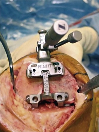
The next step is sizing and establishing rotation of the femoral component. The AP sizing guide is used to determine which of the component sizes will yield the best reconstructive result. Ideally, the body of the guide will contact the resected distal femur. Both of the guide’s feet should rest on the posterior femoral condyles. The guide is then pinned to the distal femur with two short threaded pins (Fig. 111-15). The guide’s anterior boom should contact the anterior cortex of the femur. The boom should be positioned so that it does not contact abnormal bony anatomy, such as an osteophyte or a depression. Occasionally, large anterior osteophytes must be removed to ensure accurate sizing. The ideal position to determine the size is with the boom at the beginning of the upslope of the lateral trochlear ridge. The femoral size should then be read directly from the guide. If the guide falls between sizes, the closest size is chosen. The boom can be adjusted (normally by moving it medially or more proximally) until the guide directly aligns with a size. This maneuver essentially allows the AP sizing guide to be used in a posterior referencing manner. By adjusting the boom, the surgeon can optimize the AP position of the implant using strict anterior or posterior referencing, or a combination of both techniques. Two headless holding pins are placed in the AP sizing guide’s holes. These pins are used to establish the AP position of the femoral component as well as to place it in 3 degrees of external rotation (referenced from the posterior condyles; see Fig. 111-15). The pins should be checked to ensure that they are parallel to the epicondylar axis. If the headless pins do not align with the epicondylar axis, the pins should be fine-tuned (commonly, the lateral one is adjusted) so that the pins and axis correspond. With severe valgus deformity and a deficient posterolateral femoral condyle, the surgeon may choose to increase the external rotation to 5 degrees when referenced from the posterior condyles.
Stay updated, free articles. Join our Telegram channel

Full access? Get Clinical Tree




 -inch straight osteotome.