Post–Adjustment X-Ray Evaluation
Roderic P. Rochester
Learning Objectives
After studying this chapter, the reader should learn how to:
Evaluate post–X-rays for quality control.
Refine the Adjustment based on post–X-ray reasoning.
Modify the line of correction if necessary.
Determine the probable errors made if an incomplete or asymmetrical reduction occurs.
Know how the information gleaned from the post–X-ray evaluation will influence the initial case management of the patient.
This chapter will explain the primary importance of the postAdjustment X-ray evaluation and how to use this information to modify subsequent Adjustments to result in a good outcome. An error analysis is discussed that encompasses patient placement, Adjustment line of correction (LOC), contact location, preload, hand-Adjustment errors, and Adjustment speed. A thorough understanding of Upper cervical biomechanics is necessary to derive the maximum benefit from this chapter (see Chapter 16).
Post–x-ray Reasoning
The Orthospinology procedure provides the chiropractor a method to quantify the osseous component of the upper cervical Subluxation complex. It is also understood that this procedure is not an exact science or a cookbook approach. Even with good intentions and careful application, errors can occur that result in a less-than-preferred outcome. Post–X-ray reasoning provides a means to modify the clinical procedure to account for the results of a prior Adjustment and improve the outcome. The primary value of the postAdjustment X-ray reasoning is in refining the Adjustment to more completely reduce the upper cervical misalignment.
When a less-than-expected reduction occurs following the post–X-ray analysis, it behooves the doctor to determine why and how to improve the next Adjustment. The initial radiographic analysis gives information about the type of misalignment pattern, the necessary patient placement, and the LOC for the Adjustment. However, modifications are sometimes required based on the response of each individual’s case. The most common reason for not achieving the expected results is usually an error in the following procedural steps: an initial error in the X-ray analysis; patient placement on the table (Mastoid support); speed, depth, or duration of the Thrust; and/or the LOC used with the Adjustment. To make modifications, first re-exam the pre–X-rays to determine if any errors were made in the analysis of the film. Next, re-examine the patient placement, Mastoid support, and measurements for the LOC. Always make sure that the radiographs have virtually no Image rotation (≤1°) and were taken at the proper S-line (see Chapter 8). Once these steps are completed and there is confidence that no error(s) were made, then the LOC may need to be modified. The following steps should be followed to assist with postradiographic reasoning:
Analyze the postAdjustment X-rays, and record the findings.
Compare the postfindings with the prefindings.
Check the table to determine the probable cause for unequal reductions (Table 20-1).
Using the probable errors table, check each error listed for likeliness based on the specific unequal reduction from the postfilm analysis for the patient’s case. The doctor needs to try to eliminate the error
source(s). For example, if the table indicates a possible error with the Mastoid support and this procedural step was carefully checked and rechecked before the Adjustment, then that source could be eliminated.
If the unequal reduction of the upper cervical misalignment could have been due to the LOC being too high or low, then the source of this problem must be determined. In most cases, it is due to an error in the analysis of the preAdjustment X-rays. Research has shown that the location of the X-ray analysis error that has the largest impact on LOC will lie in the size of the axial circle measurement, which has an average diameter measurement error of +/- 1.3 inches, resulting in a +/- ½-inch variance of the Height factor.1 Observing both the pre- and postAdjustment radiographs side by side and sometimes superimposing them will often illuminate the error. The four Height factor components should be compared on the nasium film, as well as the condylar and axial surface measurements. The location of the atlas transverse foramina on the vertex view should be checked with the film being superimposed. The inferior posterior arch attachment points should be checked to see if the distance between these points is the same width when the radiographs are superimposed, and a comparison should be made between the horizontal distance of the selected C7 points with the film superimposed to determine if an error has occurred. If the X-ray analysis error is determined, it can be corrected and an improved LOC recalculated.
If the error could have resulted from a mistake in the Adjustment, it is important to understand how it happened.
If after completing the above steps and the LOC still needs to be modified, only change it in amounts not to exceed 20% of the Height factor.
If one of the angles has changed sides, follow the procedures that are outlined in the Orthospinology classes.
TABLE 20-1 Probable Errors for Postradiographic Evaluation | ||||||||||||||||||||||||||||||||||||||||||||||||||||||||||||||||||||
|---|---|---|---|---|---|---|---|---|---|---|---|---|---|---|---|---|---|---|---|---|---|---|---|---|---|---|---|---|---|---|---|---|---|---|---|---|---|---|---|---|---|---|---|---|---|---|---|---|---|---|---|---|---|---|---|---|---|---|---|---|---|---|---|---|---|---|---|---|
| ||||||||||||||||||||||||||||||||||||||||||||||||||||||||||||||||||||


Examples: Case 1
The preAdjustment Listing is the following: atlas right 3°, odontoid right 4°, spinous right 6°, Lower angle left 4°, and Atlas rotation anterior 3°. The postAdjustment Listing is the following: atlas right 2°, odontoid right 2°, spinous right 1°, Lower angle normal (0°), and Atlas rotation also normal (Fig. 20-1). The observation is that this type of misalignment pattern is an “opposite angle,” with the Lower angle being larger. The Lower angle changed more than the upper angle in the direction of neutral following the Adjustment, and the upper angle changed slightly, but the Lower angle reduced well. The probable errors table indicates:
The LOC may have been too high (hand, handheld, and table-mounted Instrument adjusting).
The Adjustment was pushed (Hand adjusting).
There was pretravel, meaning that there was a slight Thrust before the Adjustment (hand and Handheld instrument adjusting).
The doctor did not remain over the resultant point throughout the Adjustment (hand and Handheld instrument adjusting).
The contact or preload was too heavy (hand, handheld and table-mounted Instrument adjusting).
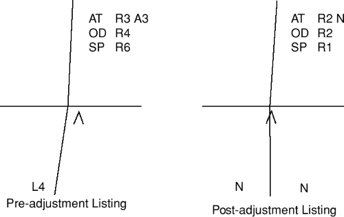 FIGURE 20-1 This line drawing represents a pre- and postAdjustment change involving an opposite-angle misalignment to demonstrate the use of the probable errors chart. |
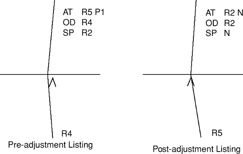 FIGURE 20-2 This line drawing represents a pre- and postAdjustment change involving an Into-the-kink misalignment to demonstrate the use of the probable errors chart.
Related posts:Stay updated, free articles. Join our Telegram channel
Full access? Get Clinical Tree
 Get Clinical Tree app for offline access

|
