Height Factors
Roderic P. Rochester
Learning Objectives
After studying this chapter, the reader should be able to:
List the four components of the Height factor formula.
Describe the purpose for each factor.
Calculate each factor, as well as the total Height factor.
Describe the purpose of the Height factor.
Demonstrate the use of a Listing card.
One of the key features of the Orthospinology procedure is that it determines a vector or pathway to apply a force to the atlas vertebra that is designed to reduce several misalignment components proportionately. The Adjustment vector has two components: the Height factor and the Rotational factor. This chapter reviews the four components that make up the formula for the calculation of the Height factor, and the rules to determine the value of each is discussed.
Plane Line
The first component of the Orthospinology Height factor is called the Plane line factor. The purpose of the Plane line factor is to enable the doctor to place his/her body or adjusting instrument in the same plane with the atlas. Essentially, it is the mathematical slope of the Atlas plane line (APL) as viewed on the nasium film. Once the Plane line factor is calculated, it is recorded on the nasium film using the symbol PL on the side of laterality in the upper right quadrant of the film just below and medial to the atlas, odontoid, and spinous measurements (Fig. 7-1).
There are two methods for the calculation of the Plane line factor.
Method 1 (Traditional)
During the analysis of the nasium film (see Chapter 5), the plane line was constructed and measured in sixteenths of an inch and recorded just below the short horizontal line that crossed the lateral margin of the jaw ramus. Use this measurement, and apply the following rule:
Add 1 inch to the Height factor for every 3/16 inch the APL is above the horizontal line on the side of Atlas laterality.
Subtract 1 inch for every 3/16 inch that the APL falls below the horizontal line on the side of Atlas laterality.
To be more accurate, round to the nearest 1/4 inch of Plane line factor. For example, if the measurement is 2/16, apply the rule above and record 3/4 inch beside the “PL” Listing as noted above. Likewise, a plane line that is high 1/16 inch would be registered as 1/4 inch for the Plane line factor. This is the traditional method, because method 2 may require a calculator for quick calculation, something that was not readily available many years ago.
The reason that 1 inch is added to the Height factor for every 3/16 inch the APL is above the horizontal line on the side of Atlas laterality is simply a mathematical calculation based on its slope or rise/run. Put another way, when the APL is above the horizontal line on the side of Atlas laterality 3/16 inch at the lateral jaw ramus, the doctor must align the episternal notch 1 inch cephalad to align his/her arms into the same plane as the atlas when the patient is in the side posture position and the doctor’s pisiform is over the atlas transverse process. It answers the question: If the Atlas plane line is above the horizontal line 3/16 inch at the edge of the jaw ramus,
how far above the horizontal line would it be at 24 inches? It is defined by the equation:
how far above the horizontal line would it be at 24 inches? It is defined by the equation:
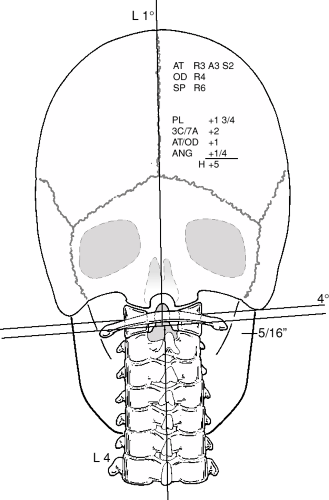 FIGURE 7-1 Final analysis with height and Rotational factors listed on the nasium X-ray. |
Y/24 inches = Z/4.5 inches
where 24 inches is the distance between a point centered between the shoulders and the pisiform while in the adjusting position, and 4.5 inches is the average width of the jaw. If Z = 0.1878 inch (3/16 inch), then Y = 1 inch.
The equivalent in degrees can be calculated using this formula:
Angle S = Arctan (H/X) (Fig. 7-2)
If H is 1 and X is 24, then angle S is 2.39°. Thus, 3/16 inch of APL rise at the jaw ramus is equal to 1 inch at 24 inches and angle of inclination 2.39°.
Method 2
This method uses a protractor at the intersection of the APL with the edge of the X-ray film to measure the inclination or slope relative to the horizontal axis. The measurement is recorded in degrees during the nasium film analysis (see Chapter 5). Use the degrees recorded, and multiply it by 0.4 inches/degree. The degrees will cancel each other, and inches of Height factor will remain. The product of this multiplication is rounded off to the nearest 1/4 inch, remembering that tolerance is always to the high side. In other words, if in doubt, round the number up in a positive direction. The final number is the Plane line factor, which is recorded by the “PL” as instructed above.
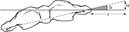 FIGURE 7-2 Atlas plane line slope. (From Eriksen K. Plane line and condylar/axial analysis factors. In: Upper Cervical Subluxation Complex. Baltimore: Lippincott Williams & Wilkins, 2004:172). |
C/A Factor
C/A stands for C over A, or the occipital condyle curvature circle over the axis joint’s surface curvature circle. The numbers were recorded during the analysis of the nasium film (see Chapter 5). It is a primary concept of Orthospinology that the atlas subluxates around the occipital condyles in a path very near an arc of a sphere or circle in two dimensions. Likewise, the atlas can subluxate laterally on the axis in a similar fashion. Knowing the diameters of these circles will aid in calculating the C/A factor. The purpose of the C/A factor is to provide a vector for a force that results in a proportional reduction of the magnitude of the Atlas laterality and Lower angle. The C/A factor is calculated in the following manner:
Related posts:

Stay updated, free articles. Join our Telegram channel

Full access? Get Clinical Tree


