Analyzing the Vertex X-ray
Kirk Eriksen
Learning Objectives
After studying this chapter, the reader should be able to do the following with the vertex view:
Draw an accurate Atlas plane line.
Construct a central skull line.
Measure and determine the degree of either anterior or posterior rotation of the atlas in relation to the occiput.
Obtain a secondary evaluation of the location for the axis spinous process and a limited pathological evaluation of the upper cervical spine.
The primary purpose of the vertex view is to measure the rotational component of the atlanto-occipital Articulation. The quantification of the misalignment is required to provide the doctor with the Rotational factor (RF) that is combined with the Height factor to provide the optimal vectored Adjustment. The RF is determined by comparing two lines: one representing the central plane of the skull and the other the central plane of the atlas. This chapter will lead the reader through a step-by-step process to help ensure the accuracy of this assessment. Two methods are discussed for finding the Central skull line (CSL) and Atlas plane line (APL). The axis spinous process can be viewed as a secondary evaluation on this film. This radiograph can also provide a pathological evaluation because the superior surface of the atlas and the axis odontoid process are visualized.
Atlas Plane Line
The Vertex X-ray is first assessed to determine if the film is acceptable for analysis. The initial step in the analysis is to locate and outline with a pencil the transverse foramina and processes of the atlas vertebra (Fig. 6-1). The ruler at the bottom of the Orthospinology analysis instrument (OAI) is used to bracket the atlas to measure and check if the foramina are approximately equal in distance from the odontoid. This double check may be slightly inaccurate at times, depending on the deviation of the axis odontoid process. A small pencil dot is then placed in the center of each foramen (Fig. 6-2). Using a straight edge, a horizontal line is drawn through these two points and should cross the entire width of the film (Fig. 6-3). However, the doctor should observe if the APL travels through each transverse process in a symmetrical fashion.
It must be kept in mind that this line is supposed to represent the plane of the atlas. The transverse foramina are used as an aid in this endeavor, although congenital asymmetry in rare cases can alter this goal. The Central ray may not be projected directly down the transverse foramina, and this may result in an oblique presentation of each transverse canal with the top and bottom of the foramen not appearing lined up. If the doctor is not careful, he/she might outline the top part of the foramen on one side and the bottom on the opposite side in error. This is not typically observed if the film is taken properly, but in certain cases, this presentation may be unavoidable. If the APL fails to appear symmetrical in relation to the atlas transverse processes, then the center of each foramen must be checked, as well as the outline of the atlas transverse processes. The centers of the transverse foramina are considered to be more symmetrical and reliable, but the transverse processes can be used as a secondary verification.
Sagittal Atlas Plane Line
A second method to determine a sagittal APL on the vertex view is available to be used to measure atlanto-occipital
rotation. This method requires the use of a compass to strike arcs anterior and posterior of the atlas around each transverse foramen. The following steps are used with this aspect of the analysis:
rotation. This method requires the use of a compass to strike arcs anterior and posterior of the atlas around each transverse foramen. The following steps are used with this aspect of the analysis:
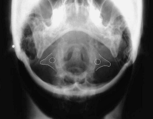 FIGURE 6-1 Outlining the atlas transverse foramina and transverse processes. |
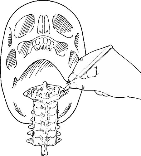 FIGURE 6-2 Marking pencil dots in the center of each atlas transverse foramina. |
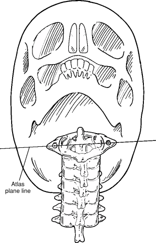 FIGURE 6-3 Drawing an Atlas plane line through symmetrically located transverse foramina. |
Place the point of the compass in the center of the transverse foramen, piercing the film and opening the instrument so the pencil will draw arcs having a radius of between 2½ to 3 inches above and below the atlas.
Strike arcs anterior and posterior of the atlas without altering the compass’s spread.
Repeat this process on the other atlas transverse foramen, maintaining the exact spread of the compass.
Place small dots at the intersections of the two arcs anterior and posterior of the atlas.
Construct a line through the intersection points of the two arcs. The resulting sagittal APL is exactly Perpendicular to the coronal APL described above and can be compared with the CSL (described later in this chapter) to determine the rotational component of the atlas relative to the skull with the use of a protractor.
Central Skull Line
The CSL is created on this view, using two points on the central plane of the skull. The location of the anterior point is determined by bisecting the Ethmoid and the site of the posterior point by using anatomical structures of the atlas or axis combined with measurements from the Nasium view. Two processes are reviewed for finding each point.
Bisecting the Ethmoid
The first step for constructing a CSL involves outlining the lateral margin of the Ethmoid (Fig. 6-4). Two methods can be used to bisect this skull structure. The ruler at the bottom of the OAI can be used to mark three small points between like areas along the lateral margins of the Ethmoid (Fig. 6-5). The doctor needs to be careful not to bisect aspects of the margins that are asymmetrical (i.e., upper aspect of the Ethmoid), as this can alter the center point somewhat. Another method involves using the vertex bracket located in the middle of the OAI. The arcs on the instrument are used to find the closest fit for the outline of the Ethmoid so that three small marks can be made in the center slot (Fig. 6-6).
Related posts:

Stay updated, free articles. Join our Telegram channel

Full access? Get Clinical Tree


