Outcome Assessments and Documentation
Kirk Eriksen
Learning Objectives
After studying this chapter, the reader should learn how to use and/or develop an appreciation for the following in his/her practice:
Paraspinal thermometry (dual-probe thermocouple and infrared scanning)
Surface electromyography
Range of motion
Paraspinal Palpation
Somatosensory evoked potentials
Activity of Daily Living questionnaires and pain scales
Documentation involved in a clinical practice
Adverse reactions related to chiropractic and medical care
This chapter covers many of the outcome assessments that have been used historically by upper cervical chiropractors. Assessments reviewed in this chapter include (i) thermometry, (ii) surface electromyography (sEMG), (iii) Range of motion (ROM), (iv) paraspinal Palpation, (v) Algometry, and (vi) activities of daily living (ADLs) questionnaires and pain scales. The reader will find step-by-step protocols for using these and other technologies/procedures in his or her practice. Somatosensory evoked potentials (SSEPs) have been used primarily in research studies as opposed to clinical practice. Chapter 9 previously reviewed recumbent and standing postural assessments that are used by upper cervical doctors. This chapter also covers the documentation that can be used in a Subluxation-based practice, as well as various adverse reactions that have been attributed to chiropractic and medical care.
The Supine leg check, paraspinal thermometry (dual-probe thermocouple or infrared scanning), scanning Palpation, postural analysis, and pain/wellness rating scales are typical assessments used by most Orthospinology practitioners on a visit-by-visit basis. ROM, sEMG, Algometry, ADL indices, and other assessments are typically used during the initial examination and at intermittent re-evaluations, although these technologies can be used during a regular office visit. The purpose of these various outcome assessments can range from determining when an appropriate chiropractic Adjustment is necessary or has been achieved to evaluating the patient’s response to care. It is not implied that all of these technologies and procedures are necessary for every patient. This is left up to the doctor’s clinical judgment for each patient, as well as the availability of the various outcome assessments.
The daily visit assessments should be in agreement for when an Adjustment is necessary, although they may show differences at times as a result of various factors. It is generally thought that the Supine leg check is the most important finding for determining the need of an upper cervical Adjustment, but cervical thermographic break analysis, cervical Palpation, and Posture analysis have been found clinically to be best at determining when a sufficient reduction has been achieved. In other words, these latter evaluations can indicate when the doctor can stop adjusting on a given visit. It is occasionally necessary to set a patient up two or more times on the adjusting table to sufficiently reduce the Subluxation. The upper cervical doctor needs objective feedback to help determine when his/her goal is achieved. As technology continues to advance, more physiologic and structural measurement devices will be developed and/or improved. Lord Kelvin, one of England’s most prominent physicists, sums up the necessity of objective measurement:
When you can measure what you are talking about and express it in numbers, you know something about it, but when you cannot measure it, when you cannot express it in numbers, your knowledge is of a meager and unsatisfactory kind; it may be the beginning of knowledge, but you have scarcely, in your thoughts, advanced to the stage of a science.1
Dual-Probe Thermometry
Paraspinal thermal symmetry is an important assessment that has been used by upper cervical doctors for more than 70 years. Its diagnostic use dates at least to the days when Hippocrates said, “Should one part of the body be hotter or colder than the rest, then disease is present in that part.”2 Dr. B. J. Palmer first introduced the Neurocalometer, which is a dual-probe thermocouple heat measuring device, to the profession in 1924. This instrument was hailed as an innovative advancement for chiropractors in the detection of upper cervical Subluxations. However, Palmer’s fervent insistence that every chiropractor have a Neurocalograph resulted in a split of the profession (see Chapter 1).3 Medical studies more than 50 years later revealed that there is very little difference in paraspinal temperature at each level of normal individuals.4,5,6,7 Uematsu et al.7 have even indicated that thermometry may be used as a way to assess sympathetic nerve function. Sensory nerve irritation and the associated involvement of the sympathetic nervous system is believed to produce reflex vasoconstriction of arterioles/capillaries in the skin, which alters thermographic patterns.
Skin temperature changes somewhat throughout the day as the body adapts to its internal and external environment. However, clinical and experimental evidence indicates that temperature differences vary only minutely at the same spinal level. This is why paraspinal thermal symmetry is a valuable clinical assessment. Sympathetic thermoregulation is primarily governed by the interaction of central autonomic control mechanisms and multisegmental spinal vasomotor reflexes. Hence, thermography/thermometry is thought to measure sympathetic-mediated tone of blood vessels in the skin. Paraspinal thermometry may be an ideal assessment for children, because they typically present to a chiropractor’s office with autonomic concomitants as opposed to musculoskeletal conditions (Fig. 10-1). Paraspinal thermometry (the measurement of temperature differences between each side of the spine) contrasts with thermography, which is a technique for detecting and measuring variations in the heat emitted by various regions of the body and transforming them into visible signals that can be recorded photographically. The primary purpose of using paraspinal thermometry is to assess the neurological component of the vertebral Subluxation complex.
 FIGURE 10-1 Demonstration of Insight dual-probe infrared scan on a small child. (Courtesy of Dr. Patrick Gentempo, Jr. and CLA) |
Break Analysis
It has been observed clinically that changing the pattern of thermographic readings or balancing the paraspinal temperature correlates with a successful spinal Adjustment. Historically, upper cervical specific practitioners have used two methods of interpretation: pattern and break analysis. Dr. John F. Grostic preferred the break analysis for the assessment of the upper cervical Subluxation. A break is determined whenever the instrument’s graph line deviates laterally at an angle of approximately 45°, with a range of 30 to 60° (Fig. 10-2). The break must also exceed a certain threshold of deviation (Fig. 10-3). This may be a function of the particular instrument, rate of glide, ambient room temperature, and/or thermal state of the patient.
Various infrared temperature devices have been shown to have great value, but the dual-probe thermocouple instruments (e.g., Neurocalometer, Nervoscope) have the longest clinical track record in upper cervical practices. Thermocouple instruments consist of two thermal sensors composed of wires of two dissimilar metals. These wires are connected at two different junctions—one for temperature measurement and the other for a reference. The temperature difference between the two junctions is detected by measuring the change in voltage (electromotive force) across the dissimilar metals at the temperature measurement junction. The dual-probe
thermocouple instrument can be connected to a graphing device to help with interpreting the patient’s scan.
thermocouple instrument can be connected to a graphing device to help with interpreting the patient’s scan.
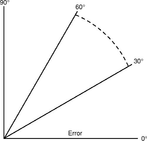 FIGURE 10-2 Range of deviation for dual-probe thermographic heat reading break. (From Eriksen K. Upper Cervical Subluxation Complex. Baltimore: Lippincott Williams … Wilkins, 2004:215.) |
A disadvantage of thermocouple instruments is that they require skin contact. However, one advantage they have over infrared instruments is that they can obtain readings into the hairline with greater accuracy because of the instrument–patient contact. A thermocouple graph is obtained by first having the patient sit erect in a room with relatively even temperature and away from any heating and cooling vents. The glide can begin at the level of T1, although Grostic recommended starting the scan at the level of C5-C6. The paraspinal scan ends at the inferior nuchal line. Great care must be given to keeping the probes Perpendicular to the contour of the neck while maintaining firm but not excessive pressure (Fig. 10-4). The contact must be of equal pressure on both sides of the paraspinal region.
False breaks can result from improper technique (i.e., unequal pressure, losing contact unilaterally or bilaterally). Various skin lesions can also affect the readings, although the patient should be evaluated before the scan for this reason as well as sanitary reasons. Scar tissue, moles, wrinkles, and excessive hair can also affect the Reliability of the readings. A false-negative scan can result from the patient’s use of nicotine, caffeine, or certain medications within a few hours before the thermal scan. Grostic thought that an accurate thermal analysis should correlate with an imbalance of the Supine leg check of at least 3/16 inch if the patient was subluxated.
Pattern Analysis
Pattern analysis is another system of interpretation used with dual-probe thermometry. It has been Hypothesized that an upper cervical Subluxation causes a patient’s paraspinal temperature readings to maintain a consistent pattern. This is established by obtaining three readings over separate time intervals before beginning care. This pattern analysis is used as a primary indicator for the need for an upper cervical Adjustment. The Hypothesis is that an optimum functioning autonomic nervous system is in a constant state of change as the body adapts to the environment to maintain homeostasis. Hart and Owens8 found that once a patient’s back is exposed to room temperature, the pattern of paraspinal skin temperature stabilized after an average of 16 minutes. The pattern analysis is more commonly used among doctors using Blair, knee chest, and Toggle recoil techniques.
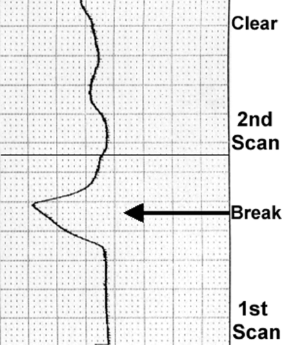 FIGURE 10-3 Dual-probe thermocouple graph demonstrating left heat reading break and its resolution after Orthospinology Adjustment. |
Reliability Studies
Owens et al.9 tested the inter- and Intraexaminer Reliability of paraspinal, infrared thermal scans using the TyTron C-3000 and found intraclass correlation coefficient (ICC) values between 0.91 and 0.98. DeBoer et al.10 also found impressive inter- and Intraexaminer Reliability (0.639–0.998 ICC) for another type of infrared heat–measuring instrument. The Gonstead Nervoscope (a thermocouple device) was found to have fair to good Interexaminer Reliability as it is used to find segmental “breaks” on the graph. Moderate to excellent Intraexaminer Reliability was found as well.11 James has presented research showing a high degree of inter- and Intraexaminer Reliability in both conducting dual-probe thermocouple scans of the posterior neck12 and in the
interpretation of the results.13 He has also found a high degree of correlation between paraspinal Palpation and Thermocouple scanning in assessing patients for upper cervical Subluxations.14 These same tests showed improved changes after Orthospinology Adjustments were provided.
interpretation of the results.13 He has also found a high degree of correlation between paraspinal Palpation and Thermocouple scanning in assessing patients for upper cervical Subluxations.14 These same tests showed improved changes after Orthospinology Adjustments were provided.
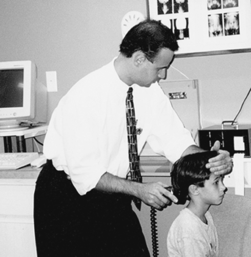 FIGURE 10-4 Demonstration of dual-probe thermocouple scan. |
Rolling Infrared Thermal Scan Protocol
The Society of Chiropractic Orthospinology has endorsed the Insight Subluxation Station™ (Chiropractic Leadership Alliance) technology since 1996. This state-of-the-art instrument is a platform of outcome assessments that measure sEMG, paraspinal infrared thermography, spinal ROM, Algometry, and heart rate variability (Fig. 10-5). The Insight™ console can make use of the following accessories to help evaluate the status of a patient’s Health and wellness:
Two-channel static/four-channel dynamic sEMG sensors
Rolling thermal scanner
Inclinometer to assess ROM
Algometer for soft tissue sensitivity testing
Pulse wave profiler to assess heart rate variability
One of the outcome assessments that this technology uses is the dual-probe, paraspinal infrared thermometry. This instrument can be used to assess autonomic function by measuring skin temperature differentials. The Insight™ software can display both pattern and segmental analysis. The computer compares the patient’s thermal readings with the normative data published by Uematsu et al.7 to determine if the patient’s scan falls outside the normal range. The segmental analysis graph displays green, blue, and red colors to indicate mild, moderate, and severe levels of thermal asymmetry, respectively (Fig. 10-6). This is the equivalent of one, two, and three standard deviations (SD) above normal values. The instrument uses noncontact thermal sensors that utilize infrared thermal imaging technology. Three thermal sensors are used, of which two are active for any one scan. Setting the thermal scan to one of three possible modes (adult, child, or infant) activates the rolling thermal sensors.
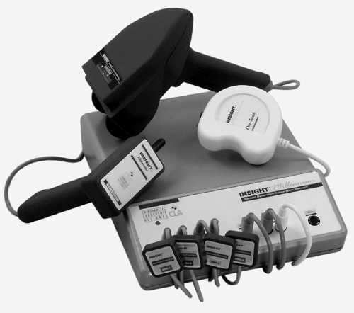 FIGURE 10-5 Insight Subluxation Station™: two-channel static and four-channel dynamic sEMG sensors, rolling thermal scanner, ROM inclinometer, and soft tissue Algometer. (Courtesy of Chiropractic Leadership Alliance) |
Rolling Thermal Scan Preparation
The rolling thermal scanner Works best in a stable environment with a temperature between 70 and 80°. Doors, entryways, and windows should be closed, and sunlight should not be directed on the thermal scanners. The exam area should not be in the immediate vicinity of heating or air-conditioning vents. If a full spine examination is conducted, women must be placed in a gown, and men must take off their shirts. This is not necessary if only a cervical scan is conducted and the patient is wearing clothing that leaves
the neck accessible. All necklaces and earrings must be removed before conducting the evaluation. Patients with long hair must have it pulled back and off the neck. At this point, allow at least 5 minutes for the patient’s skin to acclimate to the exam room’s ambient temperature. For obvious reasons, the patient’s spine must not be palpated or touched before starting the thermal scan.
the neck accessible. All necklaces and earrings must be removed before conducting the evaluation. Patients with long hair must have it pulled back and off the neck. At this point, allow at least 5 minutes for the patient’s skin to acclimate to the exam room’s ambient temperature. For obvious reasons, the patient’s spine must not be palpated or touched before starting the thermal scan.
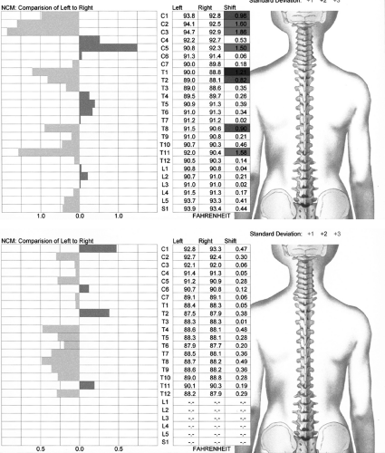 FIGURE 10-6 Pre- and postinfrared thermal scan after one Orthospinology Adjustment. |
The first step involves placing the thermal scanner at the base of the patient’s spine at the level of S1, while waiting at least 5 seconds for the initial temperature to stabilize. The scanner is then rolled slowly up the spine until reaching the top of the cervical spine. If only a cervical examination is conducted, then the instrument will be placed at the level of C7 to begin the scan. The doctor/technician will then place the scanner at like points on each side of the neck at C1, between the hairline and ear, after the rolling thermal scan is completed.
Surface Electromyography
The technology of choice for measuring the summation of muscle action potentials at the skin surface is sEMG. This is expressed as microvolts and reflects the activity of muscles as they contract and relax, as well as tone in a resting posture. This procedure has been around since 194815 and is most appropriate for kinesiological studies of global function of small muscle groups. This examination differs greatly from needle electromyography (EMG) techniques that are typically used to evaluate abnormalities in peripheral muscle activity. Such abnormalities may be due to spinal disease, nerve root irritation, peripheral nerve entrapment, or disease of the muscle itself. This test is usually used by neurologists for the purpose of diagnostic assessment.
The sEMG evaluation can be used with static and/or dynamic techniques. Static technique involves having the patient sit (or in some cases stand) in a neutral posture with handheld electrodes placed bilaterally at each paraspinal region. Dynamic sEMG involves affixing electrodes to the paraspinal region so that microvolt readings can be obtained while the patient moves through various ranges of movement. The flexion–relaxation phenomenon has been observed in “normal” subjects involving the lumbar region in particular,16,17,18,19,20,21,22,23,24 and there is some evidence that the observation may apply to the cervical spine as well.25,26 This observation includes an eccentric contraction when the spine is flexed, although when the limit of flexion is reached, the paraspinal muscles should exhibit electrical silence (Fig. 10-7). It is believed that the paraspinal muscles support the spine during flexion until the limit is reached. Support is then provided by the posterior ligamentous structures rather than the active muscles. Studies have revealed that a loss of this phenomenon is related to low back pain (LBP) and dysfunction.17,18,27,28,29
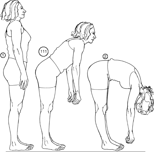 FIGURE 10-7 Lumbar flexion-relaxation phenomenon. (From Eriksen K. Upper Cervical Subluxation Complex. Baltimore: Lippincott Williams … Wilkins, 2004:219.) |
Amplitude, symmetry, and pattern are the main factors used in the interpretation of the static sEMG data. Amplitude refers to the magnitude of the signal level in microvolts. The higher the signal level, the greater the paraspinal muscle activity. These readings are compared with various normative databases,30,31,32 depending on which software and protocol the doctor uses. The previously established normative data have been obtained from an adult population. Clinical observation has demonstrated that paraspinal sEMG potentials of children are somewhat higher than those of adults. However, preliminary data have been obtained on a small population of asymptomatic children under chiropractic care.33 Symmetry refers to the comparison of left to right amplitudes at each level. This helps to determine the tonic balance of the paraspinal musculature. Donaldson and Donaldson34 found that in 97.5% of their group of patients in pain, an asymmetry of ge;20% was measured. This evaluation is particularly helpful in examining obese patients because the fat layer under the skin acts like a filter of sorts, thus reducing the amplitude of the signal for the normative data comparison. Pattern refers to the relative distribution of muscle energy throughout the spine.
The sEMG evaluation with attached electrodes has exhibited very good to excellent test–retest Reliability. Spector35 yielded correlation coefficients ranging from 0.73 to 0.97, whereas Cram36 found Reliability to be 0.83.
Researchers have found surface electrodes to have greater Reliability than needle electrodes.37,38,39,40 Komi and Buskirk37 found that the test–retest Reliability for sEMG was greater than with inserted electrodes (0.88 versus 0.62). Static sEMG scanning has also been found to be comparable to attached electrode technique,41,42 and has demonstrated moderate to high test–retest Reliability coefficients.42
Researchers have found surface electrodes to have greater Reliability than needle electrodes.37,38,39,40 Komi and Buskirk37 found that the test–retest Reliability for sEMG was greater than with inserted electrodes (0.88 versus 0.62). Static sEMG scanning has also been found to be comparable to attached electrode technique,41,42 and has demonstrated moderate to high test–retest Reliability coefficients.42
One study found the Interexaminer agreement of sEMG scans and dermothermograph measurements were poor and considered to be clinically unacceptable for evaluating the lumbar spine.43 Some authors have criticized scanning sEMG for its purported lack of sensitivity in discriminating between pain and pain-free subjects.44,45 However, Jalovaara et al.46 concluded that sEMG is a valid tool for assessing LBP patients, but not for classification into different diagnostic groups. Ambroz et al.47 conducted a study to compare 30 chronic LBP patients with 30 nonpain control subjects. A threefold increase in muscular activity was found in the chronic LBP group over that of controls (p,0.00001) with the use of static sEMG testing. Dynamic sEMG testing revealed a twofold increase in muscle activity mean values in chronic LBP patients over that of controls (p<0.00001). The authors discuss the importance of taking body mass index into consideration, because the thickness of adipose tissue may account for alteration of as much as 20% of the sEMG signal in the resting muscle and 15% in an active muscle.
Controlled and observational studies have been conducted to assess sEMG activity before and after spinal care.48,49,50,51,52,53,54,55,56,57 These studies tend to confer construct Validity for the use of sEMG in the evaluation of spine-related dysfunctions. Countless studies have been published in the medical literature involving sEMG in the evaluation of spinal conditions, but a discussion of these studies in beyond the scope of this chapter. Indeed, although some opionions may vary on its use as a diagnostic for pain, the preponderance of evidence clearly supports the use of sEMG in the evaluation of the muscular component of the vertebral Subluxation complex. This has led to its inclusion in international chiropractic guidelines.58,59 It is the position of Orthospinology that scanning sEMG is primarily used as a physiological assessment (i.e., blood pressure, temperature) and is not used as a stand-alone test for diagnosing specific disease(s).
Protocol for Conducting a Surface Electromyography Exam
Under some circumstances, excess electrical noise can adversely affect the collection of sEMG data. Examples of some devices that may cause such interference include X-ray view boxes; additional computer monitors; television screens; fluorescent, halogen, or neon lights; stereo subwoofers; and autoclaves. If any of the above devices are present in the exam area, they should be turned off or removed before the sEMG scan is being performed. A bare tiled or wooden floor is recommended for the exam area, as carpet can produce static electrical buildup on the patient, the examiner, and the equipment. If the exam area is carpeted, an antistatic mat is recommended. Software incorporating digital signal processing may be used to filter out undesired signals.
Static Surface Electromyography Patient Preparation
A patient coming in for an sEMG scan should not be taking any medication that would affect muscular activity (i.e., muscle relaxants, steroids) and should refrain from any strenuous muscular activity in the hours before the sEMG scan. However, the patient should consult with his or her medical physician before discontinuing prescribed medication. To prepare for the examination, men must remove their shirt and women must get into a gown. Long hair must be pulled up and off the patient’s neck or back, and necklaces need to be removed. The patient’s spine is then wiped down with isopropyl alcohol and allowed to dry. The patient should be sitting with both feet flat on the floor and hands palms up resting on the lap, looking straight ahead, and remaining as stationary as possible. The patient should be reminded to relax during the examination to help obtain stable signals more rapidly.
When using the sEMG scanners, the doctor/technician should apply enough pressure to indent the patient’s skin somewhat, as this will help to assure that a good ground is established (Fig. 10-8). The doctor/technician should be sure to stay out of the hairline when scanning C1 and C3. The sEMG scanner tips should be lightly dipped onto a sponge that is soaked in alcohol. The sponge can be held in a small jar, and the dipping process should take place about every other scan level. The doctor monitors the blue and red polygraph lines on the computer screen as the handheld scanners are placed on the patient. The blue line represents the microvolts that are picked up from the right scanner, and the red line represents the sEMG signal from the left handheld scanner. The foot pedal should not be pressed to record a segmental reading until these lines on the monitor graph have stabilized.
The lines on the graph do not have to come together; in fact, if there is muscle asymmetry, the lines will never come together. A stable signal will show that both lines are close to being horizontal and have a relatively smooth configuration. However, if the patient’s muscles are severely Hypertonic, the lines may never stabilize because of increased spasm. In these cases, the foot pedal should be pressed at the center of the ranges. The following levels are assessed for sEMG activity: C1, C3, C5, C7, T1, T4, T6, T8, T10, T12, L1, L3, and L5. The patient’s microvolt readings are compared with a normative
database32 to determine if they are within the normal range or if the readings are 1, 2, or 3 SDs above normal and are represented as green, blue, or red, respectively. Levels that are found to be below normal, or microvolt readings found to be >3 SDs above normal, are represented on the report as yellow and black, respectively.
database32 to determine if they are within the normal range or if the readings are 1, 2, or 3 SDs above normal and are represented as green, blue, or red, respectively. Levels that are found to be below normal, or microvolt readings found to be >3 SDs above normal, are represented on the report as yellow and black, respectively.
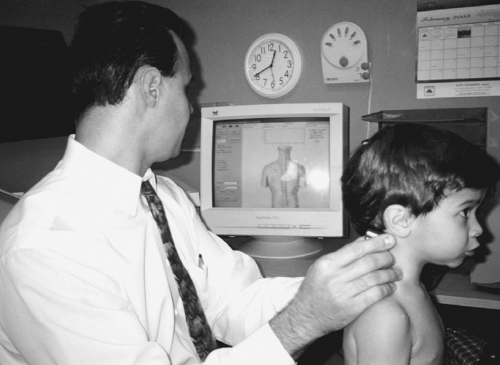 FIGURE 10-8 Demonstration of sEMG scan. |
The software can also assess the patient’s muscle tone asymmetry by depicting the amount of muscle contraction from one side to another. This is important because one of the Orthospinology doctor’s primary visit-by-visit assessments is the Supine leg check. This evaluation provides a qualitative assessment of the imbalance in paraspinal postural muscle tone, whereas the sEMG can provide a quantitative assessment. The Insight™ sEMG report will reveal either white spikes or no spikes that denote normal symmetry; green, blue, and red represent mild, moderate, and severe levels of muscle asymmetry, respectively. The program produces a color graphical display to demonstrate the examination findings, and a copy can be provided to the patient and placed in the case file (Fig. 10-9).
Dynamic Surface Electromyography Examination
The Insight™ also has the capability of conducting dynamic sEMG scans that can track up to four channels of muscle activity while the patient goes through various ROM activity. The electrodes can be affixed to the paraspinal region(s) being examined. The patient is typically asked to move the neck and/or low back through flexion and extension, as well as bilateral lateral flexion and rotation. The computer provides a graphical display that demonstrates the magnitude of paraspinal muscular contraction and relaxation that results. The flexion-relaxation phenomenon was previously explained; however, the doctor should be interested in determining the degree of left to right symmetry of the graphic display for lateral flexion and rotation.
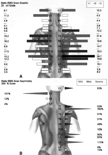 FIGURE 10-9 Example of static sEMG report. A: Display showing levels of Hypertonic muscle activity as it compares with a normative database. B: Display of paraspinal muscle asymmetry. |
Spinal Range of Motion
Spinal ROM has been established as a valid outcome assessment in the management of spine-related disorders. It is also a long-held belief by the medical and chiropractic professions that restricted spinal movement (both global and segmental) is typically related to vertebral joint dysfunction. Edmondston et al.60 found that craniocervical posture influenced cervical ROM and normal coupled motion in 30 asymptomatic subjects. Several studies have been conducted assessing ROM before and after cervical Manipulation (manual and instrument assisted),61,62,63,64,65,66,67,68,69,70,71,72 and improved ROM has been shown after specific upper cervical Adjustments.73,74 Cassidy et al.69 demonstrated that a single Manipulation was more effective than mobilization in decreasing pain in patients with mechanical neck pain, although both treatments increased cervical ROM
to a similar degree. One study has even produced data suggesting that there are early ROM changes associated with the development of neck pain.75
to a similar degree. One study has even produced data suggesting that there are early ROM changes associated with the development of neck pain.75
It is my opinion that visual assessment of spinal ROM has limited value at best and is inappropriate at worst. This is due to the fact that regional spine motion is a compound movement, and it is essential to simultaneously measure the upper and lower extremes of the spinal region being examined (with the exception of cervical rotation in the supine position). The use of a standard inclinometer is an inexpensive, yet proficient method of measuring this patient outcome that cannot be accomplished visually. The use of a goniometer is not considered to be as reliable as an inclinometer(s) in measuring spinal ROM and is considered to be inappropriate for use in determining impairment.76 Inclinometry is a means of measuring motion against a constant vertical component of Gravity as a reference. Mechanical, fluid-filled, electronic, and computerized inclinometers are available for use by physicians. The Insight™ inclinometer uses computerized technology to perform standard two-point ROM assessment. The inclinometry protocol evaluates endpoint ROM as compared with normative data, which then provides the percentage of Hypo– or Hypermobility. However, “normal” ROM is a relative term because of variations in patients’ age, size, and sex.
Spinal Range-of-Motion Examination Protocol
The Norotrack Analyzer 360 system (Myotronics-Noromed, Inc.) is another option for assessing dynamic motion of the spine. This technology can provide valuable information regarding ROM, motion control (smoothness of recording data), consistency, coordination, and timing of the movement. The Norotrack 360 uses dynamic tracking technology, which simultaneously records the motion of two segments of the spine and displays it in a graphical representation on the computer screen. This system documents the active motion of the spine by providing quantity (static ROM) and quality (pattern) of movements. Each ROM can be measured three consecutive times to establish an average. If the mean measurement is <50°, then each of the three movements should fall within 5° of the average. If the mean ROM is >50°, then each of the three measurements should fall within 10% of the average.76 This assessment can be referred to as the Validity test, which ensures that the doctor has accurate data, and as a secondary screening for possible malingering. Another Validity test for lumbosacral flexion and extension involves the use of the straight-leg-raising angle with the ROM.
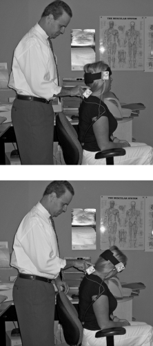 FIGURE 10-10 Demonstration of cervical flexion ROM using the Norotrack 360. |
Cervical ROM is measured by attaching lightweight inclinometers to a Velcro strap that is placed on the head. The examiner holds the inclinometer at the level of T1, although Velcro straps are available for this region as well. The inclinometer is held by the examiner so that it will move with the patient’s body as they move through the ROM (Fig. 10-10). The recording of the sensor at T1 is subtracted from the recording at the head to produce the differential recording graph, which
represents the true motion of the patient’s cervical spine during flexion, extension, and lateral flexion motions. Measuring cervical rotation involves the use of one inclinometer with the patient in the supine position. The Insight and Norotrack technologies are also capable of recording ROM of the thoracic and lumbar spine, as well as extremities. The software compares the patient’s readings with normative data retrieved from the Guides to the Evaluation of Permanent Impairment.76
represents the true motion of the patient’s cervical spine during flexion, extension, and lateral flexion motions. Measuring cervical rotation involves the use of one inclinometer with the patient in the supine position. The Insight and Norotrack technologies are also capable of recording ROM of the thoracic and lumbar spine, as well as extremities. The software compares the patient’s readings with normative data retrieved from the Guides to the Evaluation of Permanent Impairment.76
Cervical Palpation
Static Palpation has been a valuable skill used by chiropractors since the profession’s inception. Cervical paraspinal Palpation is used to demonstrate the degree of muscle spasm, trigger points, and suboccipital tenderness before and after an upper cervical Adjustment. Feedback indicating the condition of paraspinal musculature provides the doctor with information about the patient’s clinical status. Cervical Palpation can be useful if conducted before and after an Orthospinology Adjustment. The change in cervical palpatory tone is usually profound if a significant correction is achieved. This provides the doctor and patient immediate feedback about the effectiveness of the Adjustment.
Sweat et al.77 found good Interexaminer Reliability for cervical scanning Palpation conducted by two chiropractors, although poor Reliability was found with a dentist and medical doctor performing the assessment. Hubka and Phelan78 found good Interexaminer Reliability (kappa = 0.68, p<0.001, percent agreement 76.6%) for manual Palpation of the cervical spine to determine tenderness in neck-pain patients. Excellent to complete Interexaminer agreement has also been found in detecting painful upper cervical joint dysfunctions.79 However, one study involving two physiotherapists only found acceptable Reliability for one of three Palpation tests for pain, among other physical examinations of the neck.80 A systematic review of 49 studies found that the Interexaminer and Intraexaminer Reliability of spinal Palpation for pain provocation was acceptable. It was also found that regional ROM is more reliable than segmental ROM.81 A large retrospective study failed to demonstrate a correlation between Grostic radiographic Listings and cervical palpatory tenderness, among other evaluations.82 However, one small study provided data that seemed to indicate a possible link between the two variables.83
Scanning Cervical Palpation
Cervical scanning Palpation is conducted by gently cradling the patient’s head with the doctor’s left hand (assuming the doctor is right-handed). The right side of the patient’s cervical spine is palpated with the distal end of the middle and/or index finger of the right hand, while the left side is examined with the distal end of the right thumb. The pressure applied to the cervical spine during the examination should be sufficient to produce moderate compaction of the soft tissue over the articular/neurological structures. Digital pressure is initially applied over the C1 spinal nerve area inferior to the occiput and superior to the posterior lateral aspect of the atlas posterior arch. Palpation is done one side at a time, and care should be made to use equal pressure on each side of the patient’s cervical spine. Next, digital pressure is applied over the region of the C2 spinal nerve ganglion, which is located inferior to the C2 posterior arch and superior to the axis lamina (Fig. 10-11). Palpation can continue down to the mid- or lower cervical spine and should be directed to the soft tissue over the cervical facet joints. Palpatory findings should be recorded in the patient’s office visit note as normal, mild, moderate, or severe (e.g., 0, +1, +2, +3). This is based on the subjective response of the patient as well as the results of the doctor’s own Palpation.
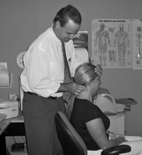 FIGURE 10-11 Cervical scanning Palpation. |
Motion Palpation of the Cervical Spine
Deboer et al.84 found statistically significant agreement for segmental fixation findings in the lower cervical spine, total lack of agreement in the middle cervical area, and intermediate Reliability for the upper cervical
region, as well as other Palpation parameters (e.g., muscle spasms, pain). Another study assessed passive intervertebral motion of three cervical segments and the mobility of the first rib. Sixty-one patients seeking care for cervical problems were evaluated by two physical therapists. The results demonstrated Interexaminer Reliability of between 70% and 87% and kappa coefficients ranging between 0.28 and 0.43, which is considered to be only fair to moderate.85 A systematic review of the literature found that overall Interexaminer Reliability for motion Palpation in the cervical and lumbar spine was poor to fair.86 However, assessment of motion segments C1-C2 and C2-C3 almost consistently reached at least fair Reliability. Indeed, the preponderance of evidence indicates that the Reliability of cervical motion Palpation is relatively poor.87,88,89,90,91,92,93 Orthospinology protocol does not typically include motion Palpation of the cervical spine because of the kinematic complexity of the upper cervical region and lack of Reliability of the evaluation from an evidence-based standpoint.
region, as well as other Palpation parameters (e.g., muscle spasms, pain). Another study assessed passive intervertebral motion of three cervical segments and the mobility of the first rib. Sixty-one patients seeking care for cervical problems were evaluated by two physical therapists. The results demonstrated Interexaminer Reliability of between 70% and 87% and kappa coefficients ranging between 0.28 and 0.43, which is considered to be only fair to moderate.85 A systematic review of the literature found that overall Interexaminer Reliability for motion Palpation in the cervical and lumbar spine was poor to fair.86 However, assessment of motion segments C1-C2 and C2-C3 almost consistently reached at least fair Reliability. Indeed, the preponderance of evidence indicates that the Reliability of cervical motion Palpation is relatively poor.87,88,89,90,91,92,93 Orthospinology protocol does not typically include motion Palpation of the cervical spine because of the kinematic complexity of the upper cervical region and lack of Reliability of the evaluation from an evidence-based standpoint.
Algometry
Measuring sensitivity to pain and pressure is called Algometry. The objectivity of paraspinal Palpation can be improved with the use of a force gauge called an Algometer. A handheld Algometer consists of a force dial that reads in kilograms or pounds and a 1-centimeter diameter rubber-tipped stylus. Assessing Pressure pain threshold (PPT) is preferred over pressure tolerance (PT). PPT involves applying a slow steady pressure (approximately 1 kg/s) with the force gauge over specific body regions until the patient first perceives discomfort or pain. PT involves applying pressure with the Algometer to the point of maximum pain tolerance by the patient. The PT examination is more traumatic to the patient than PPT, and it also suffers from reduced reproducibility because of the nature of the procedure. Measurements are usually recorded to the nearest tenth of a kilogram at strategic points along the spine with the chiropractic examination.
Normative data has been established for upper trapezius, levator scapulae, gluteus medius, and lumbar paraspinal regions.94 PPTs tend to be highly symmetrical in normal subjects and are generally lower in women compared with men. Fischer95 has found that a side-to-side difference exceeding 2 kilograms is indicative of pathologic tenderness. Takala96 demonstrated Intraexaminer Reliability coefficients ranging from 0.71 to 0.92 while assessing PPT over the upper trapezius and levator scapulae muscles in 93 men and 70 women. This same study found acceptable day-to-day measurement repeatability, and Interexaminer Reliability coefficients on the men were found to range from 0.68 to 0.79. Reeves et al.97 have reported Algometry Reliability coefficients ranging from 0.71 to 0.97. Chiropractic studies have shown improvement in PPT after cervical Manipulation98,99 and upper cervical Adjustments.100 Algometry can be further objectified with the use of computerized assessments such as the Insight™ Algometer. This technology uses a handheld device that accurately quantifies the sensitivity of paraspinal tissues and graphically displays the progress throughout a course of care.
Related posts:

Stay updated, free articles. Join our Telegram channel

Full access? Get Clinical Tree


