Patient Placement for Cervical Radiographs
Kirk Eriksen
Learning Objectives
After studying this chapter, the reader should be able to:
Prepare a patient to receive the cervical X-ray series while sitting in the turntable chair
Place a patient for a lateral cervical radiograph for the purpose of pathological and biomechanical assessment
Place a patient for appropriate vertex and nasium X-rays
Use Head clamps during the setup of the cervical film
Modify placement for the nasium and vertex views for patients with extreme head tilt
Determine if each of the cervical X-rays was taken properly
Take a specific cervical anterior-to-posterior (AP) open-mouth view
Proper X-ray positioning is an essential part of patient care. The patient must be accurately and precisely placed for the radiographs, because measurements will be made to the nearest quarter degree. Obtaining acceptable film marks the first step in the process that leads to the Adjustment, so a detailed protocol must be followed to accomplish this goal. Likewise, any inaccuracies at this point will tend to propagate in the remaining steps of the Orthospinology procedure. Attention to detail will be beneficial for the doctor because accurate, clear X-rays can be read faster and with greater Reliability than those of poorer quality. However, the process of patient placement for taking Orthospinology film is an art as well as a science. This chapter will cover the procedural steps that will help ensure that the X-rays produced are technically and analytically sound.
Three standard views are used in the Orthospinology analysis: lateral, nasium, and Vertex X-rays. However, a precisely taken anterior to posterior (AP) open-mouth radiograph is used in many cases as well. These X-rays provide the doctor a three-dimensional view of the cervical spine and the osseous component of the upper cervical Subluxation. The patient should always be in a normal and comfortable position during placement of these radiographs. The patient’s head and neck should never be forced into position. It is highly recommended that all cervical X-rays be taken on 10 × 12–inch or 24 × 30–centimeter film to enable all osseous structure to be easily visible. It is also recommended that the X-ray cassettes have the name blockers located vertically along the lateral edge of the film so that this information does not obscure osseous structures (see Chapter 2, Fig. 2-6). All radiographs should include the following:
Patient’s name
Patient’s age or date of birth
Patient’s identification number
Clinic or doctor’s name
Location where study was performed
Date of the film
A right or left marker
A means of identifying the view if not obvious from the X-ray (e.g., obliques and other studies in which right and left could be confused)
Placement for the Lateral View
One purpose of the neutral Lateral cervical view is to initially assess the Sagittal plane of the atlas vertebra. This slope is necessary for taking the nasium X-ray. The lateral view will also allow the doctor to find the atlas transverse process in relationship to the Mastoid process and ramus of the mandible. This information is
essential for determining the contact point for delivering the Adjustment. The doctor should assess the pathological and overall biomechanical integrity of the film as well. However, the first step involves taking a high-quality X-ray that will enable the doctor to make an accurate analysis. As is the case with all radiographic studies, it is important not to engage in conversation with the patient during the setup process. This will help prevent the patient from moving and altering the placement and keep the doctor’s or technician’s focus and attention on the task at hand.
essential for determining the contact point for delivering the Adjustment. The doctor should assess the pathological and overall biomechanical integrity of the film as well. However, the first step involves taking a high-quality X-ray that will enable the doctor to make an accurate analysis. As is the case with all radiographic studies, it is important not to engage in conversation with the patient during the setup process. This will help prevent the patient from moving and altering the placement and keep the doctor’s or technician’s focus and attention on the task at hand.
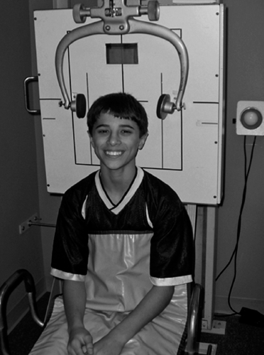 FIGURE 3-1 Patient wearing half lead apron while sitting in turntable chair. |
The first step is carefully placing the patient in the X-ray turntable chair. The patient is then asked to remove all Radiopaque articles (e.g., hairpins, jewelry, dental plates) that will be located in the region being exposed. It is recommended that a half lead apron (Fig. 3-1) be placed that will cover the patient’s chest/breast region, the lap, and the upper legs. A piece of lead shot will then be taped to the anterior/inferior corner of the patient’s earlobe closest to the grid cabinet (Fig. 3-2). This landmark point on the radiograph will be transferred to the patient’s Listing card (see Chapter 7, Fig. 7-3), and it will be used as a reference point to help the doctor locate the patient’s Atlas transverse process contact. The patient is instructed to remain in a relaxed, neutral posture while sitting upright and having the hard palette level with the floor. The doctor will then observe the patient’s body structure and if necessary, make caliper measurements to determine the X-ray factors that will be used to expose this view. These factors are then set on the X-ray machine’s control panel and recorded on the patient’s Listing card.
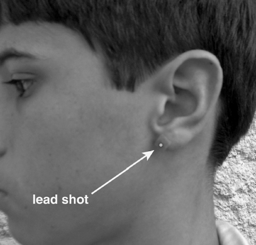 FIGURE 3-2 Lead shot taped to patient’s earlobe. |
The patient is placed with the shoulder slightly against the grid cabinet, which is set so that it is parallel to the contour of the plane of the head and neck. It is recommended that mild to moderate head deviation should be removed manually, as opposed to leaning the patient or turning the chair. This helps to insure that like structures are parallel to the film for the lower cervical spine as well as the upper cervical spine. Rotating the chair may cause these structures to not be parallel, and this may affect the reading of the film from a pathological standpoint. Also, the cervical Lordosis may be distorted as a result of rotating the chair a significant amount. However, patients presenting in a torticollis like state should lean slightly away from the side of head tilt, and the grid cabinet should be tilted to conform to the slope of the head. The chair should be rotated to remove head rotation in this rare situation.
The X-ray tube should be set so that the Central ray is Perpendicular to the grid cabinet. Using the horizontal crosshair on the collimator light, the tube is positioned so that the Central ray will pass through the center of the atlas transverse process and project it to the center of the film (Fig. 3-3). This protocol is very important to prevent distortion of the location for the atlas
transverse processes because of the nature of the divergent rays. Removal of head tilt and rotation is also essential to prevent atlas contact distortion. It must be emphasized that determining the precise location of the Atlas transverse process contact is vitally important in the administration of the Orthospinology Adjustment.
transverse processes because of the nature of the divergent rays. Removal of head tilt and rotation is also essential to prevent atlas contact distortion. It must be emphasized that determining the precise location of the Atlas transverse process contact is vitally important in the administration of the Orthospinology Adjustment.
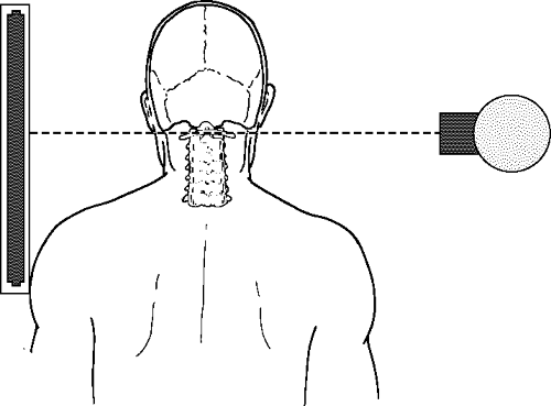 FIGURE 3-3 The Central ray is shown projecting through the center of the atlas transverse process and to the center of the film. |
The patient is moved with the turntable chair so that the vertical crosshair collimator light projects over the atlas transverse process. This will serve as an initial setup in the AP dimension. At this point, the Central ray should be set up to project to the center of the grid cabinet. An exception to this rule would be with patients that are very tall and/or have long necks. In this case, the grid cabinet should be lowered so that the atlas will project above the center of the film for all seven cervical vertebrae to be visualized. The Central ray is still projected at the level of the atlas vertebra to prevent distortion of the transverse processes. In this situation, the tube is tilted down so that the collimator light projects to the center of the film.
An alternative placement method can also be utilized, particularly if an 8′ × 10′ film is used for the Lateral cervical view. The grid cabinet is adjusted vertically so that the atlas aligns with the tape marker placed 2 inches above the film’s horizontal center line. The tube is also set so that the Central ray projects through the atlas transverse process and to the 2-inch marker on the grid cabinet. The tube is then tilted so the collimator light is aimed at the center of the film. It is not important to have the top of the patient’s skull appear on the X-ray, but it is essential that all cervical vertebrae be visualized, with rare exception.
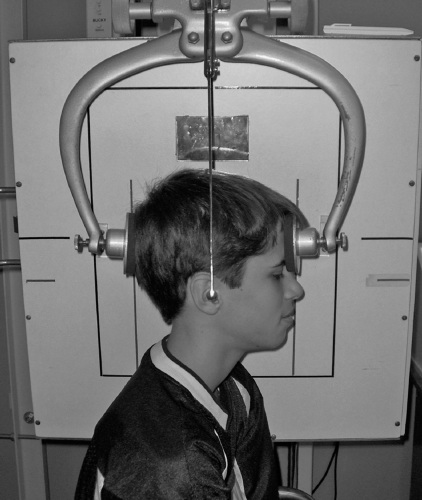 FIGURE 3-4 Positioning the alignment rod over the atlas transverse process. |
The Head clamps can then be brought down from their resting position so they are at the level of the top one-third of the head. The alignment rod should be positioned over the atlas transverse process on the side facing the X-ray tube (Fig. 3-4). The doctor/technician can then use the vertical line on the grid cabinet mirror to make sure that this line crosses over the same atlas reference point as the alignment rod on the opposite side. This will help remove any inherent head rotation left during the setup, as well as center the patient in the AP dimension. The Head clamps and alignment rod are then moved out of the field of exposure. However, doctors have traditionally used the Head clamps to stabilize the head and help secure proper placement. If this method is used, a sponge may have to be placed between the back of the head and the clamp pad so that the Head clamps contact the patient’s head evenly.
It is recommended that the lateral cervical X-ray be taken at a 72′ Focal film distance (FFD), or as close to this as possible, to prevent magnification of the anatomical structures that is due to the distance between the shoulder and the grid cabinet. This is an important issue when the doctor tries to quantify the patient’s sagittal stenosis and when he/she tries to locate the superior tip of the axis spinous process on the nasium film in relation to the Atlas plane line (see Chapter 5, Fig. 5.10). It may be necessary to use a lead foil compensating filter (LFCF) (see Chapter 2) for large patients with relatively short and/or thick necks. Attenuating the beam to the region above the slope of the trapezius
muscle can be quite helpful with visualizing the lower cervical vertebrae without “burning out” the mid- to upper cervical spine. Finally, the doctor or technician must recheck the patient setup to make sure that the hard palette is level and there is no head tilt or rotation. Collimation needs to be minimal in the AP dimension to prevent cutting off facial structures, which will make it more difficult to obtain an accurate S-line. The X-ray is then taken and developed (Fig. 3-5).
muscle can be quite helpful with visualizing the lower cervical vertebrae without “burning out” the mid- to upper cervical spine. Finally, the doctor or technician must recheck the patient setup to make sure that the hard palette is level and there is no head tilt or rotation. Collimation needs to be minimal in the AP dimension to prevent cutting off facial structures, which will make it more difficult to obtain an accurate S-line. The X-ray is then taken and developed (Fig. 3-5).
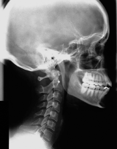 FIGURE 3-5 Example of a properly taken lateral cervical X-ray. |
Potential Placement Errors for the Lateral Cervical
Potential patient placement errors (Fig. 3-6) must be carefully avoided as they can include the following:
Hard palette not positioned parallel with the floor
Head tilt or rotation left during patient placement, causing difficulty in locating the atlas transverse process on the film
Grid cabinet placed too high, causing the seventh cervical vertebra to be cut off on the film
Atlas not centered in the AP dimension, resulting in too much of either the facial structures or posterior aspects of the lower cervical vertebrae to be cut off on the film
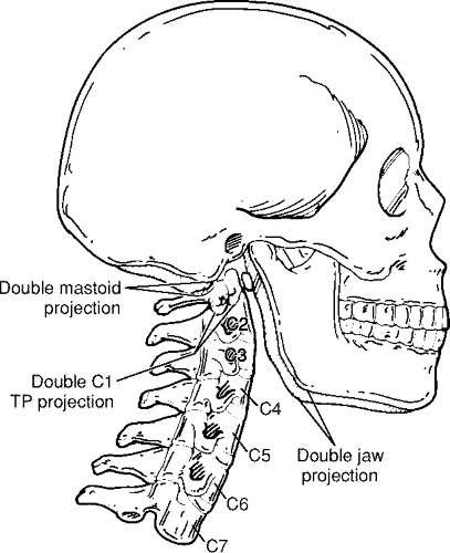 FIGURE 3-6 Example of improperly taken lateral cervical X-ray. |
Placement for the Vertex View
Related posts:

Stay updated, free articles. Join our Telegram channel

Full access? Get Clinical Tree


