(5.1)
If the bone plate fractures before the proof point (yield point), the bending strength is defined as the bending moment at fracture. In this case, fracture load, F max, takes the place of P in the above bending strength equation.
Bending stiffness, K (N/mm) of a bone plate
the slope of the linear elastic portion of load versus displacement curve (slope of the straight line, Om; see Fig. 5.3).
Bending structural stiffness, Ele (Nm2) of a specimen
normalized effective bending stiffness of specimen that takes account of the effects of test configuration. The bending structural stiffness of the specimen is determined by Eq. 5.2.
(5.2)
Proof Load, P (N)
applied load at the intersection point of offset line with load versus displacement curve. It can be referred as yield load also.
M-N diagram
a diagram of maximum moment versus number of cycles. A semi-log M-N diagram characterizes the general fatigue behavior of the (specimen) under a range of bending loadings.
Maximum and minimum moments
the applied bending moments which have the highest and lowest algebraic values, respectively.
Median fatigue strength at N cycles
at a given R ratio, an estimation of the maximum moment at the situation that 50 % of the test specimens would be expected to survive until N cycles.
R ratio
the ratio of minimum moment to maximum moment.
Run-out
number of cycles at which the testing of the specimen completed without failure. The run-out is specified before the test. If the purpose is to determine fatigue strength at N cycles, the run-out is generally determined as N cycles.
Lever arm of an angled device, L (mm)
the distance between the line of load application and sideplate surface that contact with rigid support mimicking the bone.
Compression-bending stiffness, K (N/m), of an angled device
calculated like bending stiffness of a bone plate in ASTM F382 (slope of the straight line, Om; see Fig. 5.3).
Compression-bending strength, (Nm), of an angled device
the bending moment which induces a 0.2 % offset displacement in the angled device. The bending strength of the angled device is determined by Eq. 5.3.
(5.3)
Torsional yield strength, N
specified by 2° offset method in the linear elastic portion of the torque versus angle of rotation curve. Point Y (see Fig. 5.8) is the torsional yield strength of the bone screw.
Maximum torque, Nm
the largest value obtained from the torque versus angle of rotation curve.
The breaking angle, degrees
the angle value that occurs when the negative slope (most rapid descent) in the torque versus angle of rotation curve is observed (B.A. point in Fig. 5.8).
Insertion and removal torques, Nm
the insertion torque is the maximum torque which occurs in initial four revolutions of the specimen. The removal torque is the maximum torque required to remove the screw from the test block in initial four revolutions of the specimen. Both torques must be less than torsional yield strength of the screw.
Axial pullout strength, N
the maximum load obtained from the load versus displacement curve. It is critical for pullout test of the bone screws.
Self-tapping force, N
the axial compression force which is necessary to engage self-tapping feature.
Total span, L
sum of the center span and two loading spans (a + 2h).

(5.4)
Torsional stiffness
the slope of the straight line which is observed in linear elastic portion of the torque versus rotation curve.
Bending yield load
specified by 2° offset method in the linear elastic portion of the load versus displacement curve.

(5.5)
In-plane compressive stiffness
the maximum slope of the initial portion of the load versus displacement curve.
In-plane compressive yield strength
specified by 2° offset method in the linear elastic portion of the load versus displacement curve.
In-plane maximum compressive strength
the maximum load value obtained from the load versus displacement curve.
Block moment arm for spinal implant subassemblies
the distance between the insertion point of a screw and axis of the hinge point, perpendicular to the applied load. The moment arms of thoracolumbar, lumbar, and lumbosacral subassemblies are 40 mm. For cervical subassemblies, the distance is 30 mm.
Active length of the longitudinal elements for spinal implant subassemblies
the longitudinal distance between insertion points of the superior and inferior screws. It is recommended as 76 mm for thoracolumbar, lumbar, and lumbosacral subassemblies and 35 mm for cervical subassemblies.
Ultimate bending strength
the maximum load value obtained from the load versus displacement curve.
S-N diagram
a diagram of maximum strength versus number of cycles. A semilog S-N diagram characterizes the general fatigue behavior of spinal implant constructs under a range of bending loads.
Maximum run-out load
the maximum load which can be applied to a test sample in the situation that all of the tested samples survive N cycles without a failure.
R ratio
the ratio of minimum load to maximum load.
Active length of longitudinal element for interconnection mechanism
the distance between the rigid supports (clamps).
Axial gripping capacity
the maximum load that occurs on the interconnection mechanism within the first 1.5 mm of permanent displacement between connected components.
Torsional gripping capacity
the maximum moment that occurs on the interconnection mechanism within the first 5° of permanent rotation between connected components.
Loosening torque
the torque required to disconnect the connected components of interconnection mechanism.
Maximum run-out load/moment
the maximum load or moment which can be applied to subassembly in the situation that all the tested constructs survive until N cycles.
Loosening torque
the torque required to disconnect the connected components of interconnection mechanism.
Bending stiffness, K (N/mm) of a rod
the slope of the linear elastic portion of load versus displacement curve (slope of the straight Om line; see Fig. 5.3).
Bending yield moment, (Nm)
the bending moment which induces a 0.2 % offset displacement in the rod.
Bending ultimate moment, (Nm)
maximum bending moment value which is applied to a test specimen.
Bending fatigue run-out moment, (N*mm)
the maximum moment which can be applied to a test specimen in the situation that all tested specimens survive until N cycles at a specified R ratio.
Ultimate displacement (mm or degree)
the displacement occurring when the ultimate load or moment is observed.
Yield displacement (mm or degree)
the displacement occurring when the yield load or moment is observed.
Functional failure
permanent deformation of the devices which can cause ineffectiveness in load carrying.
Mechanical failure
fatigue crack or surface wear of the intervertebral body fusion devices.
Locking mechanism
a design feature which restricts the movement between the acetabular liner and shell.
CT distance
distance from the most distal point of the stem to the center of the femoral head.
Endurance limit, F D
maximum load that is applied for N D cycles without failure of specimen.
Endurance cycles, N D
described number of cycles.
Wear
material loss from the joint of the components due to movement and loading.
Moment arm for tibial tray, d ap
determined as perpendicular distance between the mediolateral centerline of the tibial tray and the axis of load application.
Moment arm for tibial tray, d ml
determined as perpendicular distance between the anteroposterior centerline of the tibial tray and the axis of load application.
Introduction
The orthopedic implants are mechanically tested to determine the lifetime of an implant under physiologic loading conditions and load-bearing capacities. Mechanical tests for the inactive medical devices can be evaluated under two main categories with regard to loading conditions. These are static and dynamic loading procedures. Static tests are conducted under quasi-static loading conditions until the fracture or yielding occurrence. The term quasi-static means very small loading speeds that allowed the material to recover to some extent. Moreover, dynamic tests are generally time dependent and the application of higher numbers of cycles takes place. By this type of tests, fatigue or wear performance of the implants can be evaluated. It is important to note that an implant cannot be evaluated with static tests only. In addition, to test an implant on dynamic loading conditions, static tests are prerequisites.
In this chapter, implants will be categorized under three main subcategories to give the message as a whole picture. These are the implants that are used in spinal, trauma, and arthroplasty surgeries and will be named as spinal implants, trauma implants, and arthroplasty implants, respectively. The trauma implants are metallic bone plates, metallic angled orthopedic fracture fixation devices, metallic medical bone screws, intramedullary fixation devices, and external skeletal fixation devices. The spinal implants are pedicle screws, hooks, rods, intervertebral body fusion devices, and spinal artificial disks. The arthroplasty implants are hip joint prosthesis and knee joint prosthesis. The implants can also be categorized under two subcategories in a different approach. These are fusion implants and motion-preserving implants. The motion-preserving implants are the spinal artificial disks, hip joint prosthesis, and knee joint prosthesis. The other implants are the fusion implants.
Trauma Implants
Metallic Bone Plates
Metallic bone plates used in the treatment of trauma fractures are tested according to ASTM F382 [1]. Static testing and dynamic testing were performed to determine bending properties of the plates. The materials which show linear-elastic behavior are tested with this method, so the method is not valid for materials showing nonlinear elastic behavior. A sample of the metallic bone plate is shown in Fig. 5.1.

Fig. 5.1
A sample of the metallic bone plate
Static Testing
Four-point bending test is used as static testing to measure the relevant bending properties of bone plates, which are bending stiffness, bending structural stiffness, and bending strength.
Apparatus and Procedure
The test setup can be seen in Fig. 5.2. The vertical load must be applied to bone plates through loading rollers which directly contact to bone plates. The load acts increasingly to the bone plates. The load versus displacement diagram obtained during the test can be seen in Fig. 5.3. The diagram is used to calculate the bending strength.
Fig. 5.2
Four-point bending test setup for the metallic bone plates. (a) Schematic view, (b) view obtained from test
Fig. 5.3
Load versus displacement diagram for the metallic bone plates
An alternative test configuration (see Fig. 5.4) can be performed to determine the bending properties of bone plates if the bone plates do not have sufficiently long section or do not have a section of symmetry. In this configuration, the bone plates are attached with rigid extension segments for the purpose of lengthening. The loading rollers directly contact the rigid extension segments during the test unlike the configuration seen in Fig. 5.2.
Fig. 5.4
Alternative test setup of the four-point bending test for metallic bone plates
Interpretation of Results
If the bone plate fractures before the proof point (yield point), the bending strength is defined as the bending moment at fracture. In this case, fracture load, F max, takes the place of P in the above bending strength equation.
Dynamic Testing
The fatigue test is used as dynamic testing for such bone plates. The test method is used to determine the fatigue life of the bone implant under a specific or over a range of maximum bending moment levels. Moreover, fatigue strength (endurance limit) for a specified number of fatigue cycles of bone plates can be determined.
Apparatus and Procedure
The test setup of fatigue testing is the same as static test setup (see Fig. 5.2). A constant frequency, sinusoidal waveform cyclic load is implemented to the bone plate. To complete the test timely, the frequency is generally set to 5 Hz but it is not limited with 5 Hz. The fatigue loading proceeds until the failure of the specimen, a limit which is an indication of failure, or the run-out cycle count which is determined before to stop the test.
Interpretation of Results
The recommended fatigue strength is described as the strength occurring at 1,000,000 cycles without failure. In the estimation of median fatigue strength, N is accepted as 1,000,000 cycles. The recommended R ratio is 0.1. The run out is specified before the test. If the purpose is to determine fatigue strength at N cycles, the run-out is generally determined as N cycles.
If a specimen fails before the 1,000,000 cycles, the next specimen is tested after decreasing the load. The test is repeated until a specimen does not fail before the 1,000,000 cycles. Then, it is tried to reach that three consecutive specimens run out to 1,000,000 cycles when load is increased or decreased. This method is used to determine fatigue curve of the tested implant.
Metallic Angled Orthopedic Fracture Fixation Devices
Metallic angled devices are used in internal fixation of the skeletal system and tested in accordance with ASTM F384 [2]. Static testing and dynamic testing are performed.
Static Testing
Compression-bending test is performed as static testing. The test method is used to measure the compression-bending stiffness and compression-bending strength of the angled devices.
Apparatus and Procedure
The test apparatus of static testing is shown in Fig. 5.5. The angled device attaches to rigid support by the sideplate of the device. The load is parallel to the sideplate’s long axis. The load must be applied to lever arm length. The lever arm length is equivalent to 80 % of either blade length or the longest screw. The load must be applied increasingly with the constant crosshead speed of 10 mm/min. The load versus displacement diagram is the same as ASTM F382.
Fig. 5.5
Compression-bending test setup for the metallic angled orthopedic fracture fixation devices
Interpretation of Results
The specifications of ASTM F382 are used during determining the bending stiffness, bending structural stiffness, and bending strength of sideplate.
If the angled device failed before the proof point (yield point), the compression-bending strength is defined as the bending moment at fracture. In this case, F max takes the place of P in the bending strength equation above.
Dynamic Testing
The test method specifies the bending fatigue life of the angled device under a specific or over a range of maximum bending moment levels. Additionally, fatigue strength for a specified number of fatigue cycles of bone plates can be determined.
Apparatus and Procedure
Fatigue test is used in this method as dynamic testing. The test setup of dynamic testing is the same as static testing (see Fig. 5.5). The testing procedure is identical with those specified in ASTM F382.
Interpretation of Results
The M-N diagram, maximum and minimum moments, median fatigue strength at N cycles, and R ratio are defined before in ASTM F382.
If the purpose of the study is to test termination data, the semilog graph of M-N diagram must be plotted. If the purpose of the study is to specify the fatigue strength at 1,000,000 cycles, the fatigue strength is specified as the median fatigue limit (50 % survival).
Metallic Medical Bone Screws
Metallic medical bone screws are tested according to ASTM F543 [3]. The static test systems are used in the method, which are torsion testing, driving torque testing, axial pullout testing, and self-tapping performance testing, to determine the structural properties of metallic bone screw. A sample of the metallic medical bone screws is shown in Fig. 5.6.
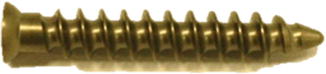
Fig. 5.6
A sample of the metallic medical bone screws
Static Testing
Apparatus and Procedure
Torsional yield strength, maximum torque (ultimate), and breaking angle of the bone screw are determined by using torsion test setup under standard conditions. The test setup for torsion test can be seen in Fig. 5.7. The threaded end of the bone screw is held by a clamp which prevents its rotation. The clamp must not hold the screw so tight because this can damage its mechanical structure. The head side of the screw is held by a screwdriver, and the screwdriver rotates the screw during the test. The speed of the screwdriver can be 1–5 r/min. Torque versus angle of rotation curve (see Fig. 5.8) is gained from the test. The torsional yield strength, maximum torque, and breaking angle are determined by using the torque versus angle of rotation curve.
Fig. 5.7
Torsion test setup for the bone screws. (a) Schematic view, (b) view obtained from the test
Fig. 5.8
Torque versus angle of rotation curve for the bone screws
The torque which is required to drive the bone screw into the standard materials is gained from the driving torque testing. The test setup for driving torque testing is shown in Fig. 5.9. The bone screw is inserted in the test block which has a pilot hole. The test block holder holds the test block rigid but not too tight, because this can deform the test block during the clamping and change the performance of the test. A replaceable bushing is placed between the screw and the test block for the purpose of suitable insertion of a screw to the test block. The screwdriver applied torsional force with the speed of 1–5 r/min.
Fig. 5.9
Driving torque test setup for the bone screws
The axial tensile force required to fail or remove the bone screw from the standard material is measured by using this method. The suitable test configuration for pullout testing is shown in Fig. 5.10. The bone screw is inserted into the test block which is fixated by the base jaw and test block holder. The axial tensile load acts on the bone screw with a rate of 5 mm/min and should be aligned with the screw’s long axis. The load is transferred through the head of the screw. The load fixture must not be in contact with the shaft of the screw and must only capture the head of the screw. The screw is inserted with a depth of 20 mm. The insertion depth is determined as 60 % of the threaded length of the screw for fully threaded screws, while the threaded depth is less than 20 mm. All threads should be inserted for partially threaded screws. The screw either can be released from the test block or can fail during the test.
 < div class='tao-gold-member'>


Only gold members can continue reading. Log In or Register to continue
Related posts:

Stay updated, free articles. Join our Telegram channel
Full access? Get Clinical Tree
