Hip Arthroscopy Anatomy and Access to the Central Compartment
James R. Ross
John C. Clohisy
Arthroscopy of the hip has emerged as a popular treatment method for a variety of hip disorders due to better diagnostic tools as well as the development of new techniques and instrumentation to facilitate surgeon access to the hip joint in a minimally invasive manner. Hip arthroscopy was first introduced by Burman in 1931 (1), who described the difficulty in the arthroscopic evaluation of the cadaveric hip joint given the inability to distract the joint and access the central compartment of the hip. The first clinical application was not until 1977, when Gross (2) reported about his use of arthroscopy in the treatment of patients with congenitally dislocated hips. Clinical application of arthroscopy in the hip joint continued to be published sporadically, with applications in patients with total joint arthroplasty (3,4) and as a diagnostic tool for the evaluation of patients with juvenile chronic arthritis (5).
During the late 1980s and early 1990s, many hip arthroscopists brought attention to the technical considerations of this procedure. In light of the known difficulty accessing the central compartment of the hip, Eriksson (6) recorded the forces that were necessary to adequately distract the hip joint for arthroscopy, pointing out that 300 to 500 N was required for adequate distraction of an anesthetized patient. Techniques of cannula placement and anatomical landmarks about the hip were introduced and Glick (7,8) described lateral decubitus positioning and the details in regard to peritrochanteric portal placement. This was soon followed by many others who described additional advances, which further refined the techniques that are classically used today (9,10,11,12,13,14).
Hip arthroscopy enables the surgeon to thoroughly inspect the hip joint and treat a variety of disorders that were historically undiagnosed or treated with open arthrotomy. This technique also provides the surgeon the ability to treat various disorders in a more minimally invasive manner, which has the potential to allow a quicker recovery and faster rehabilitation. Hip arthroscopy is technically more demanding than arthroscopy of other common joints, such as the knee and the shoulder. Surgeons who wish to perform this technique should have a strong understanding of surface anatomy as well as intra- and extra-articular anatomy. In addition to anatomical knowledge, one must understand the pathologic processes to provide appropriate, patient-specific treatment in a safe manner. The limitations of hip arthroscopy must also be appreciated, since many hip disorders are managed more effectively with open techniques.
Anatomy
The anatomy of the normal hip joint is represented by the articulation between the head of the femur and the acetabulum of the pelvis. The femoral head is deeply recessed within the acetabulum, creating an inherently stable joint. In addition to this relatively constrained bony anatomy, a thick fibrous capsule with ligamentous condensations (pubofemoral, iliofemoral, and ischiofemoral ligaments) provide further support and adds to the stability of the hip joint. Furthermore, the hip joint is covered by a large soft tissue envelope consisting of muscular, tendinous, and neurovascular structures. The combination of the osseous anatomy with the surrounding ligamentous structures thus makes hip arthroscopy challenging to the surgeon that is unfamiliar with the finer techniques that are required to gain safe access to the hip joint. The hip surgeon should therefore have a sound knowledge of the anatomy of the hip to ensure efficient, yet safe treatment of various hip disorders.
Hip arthroscopists commonly describe the femoroacetabular joint and its surrounding areas by dividing the anatomy into three separate compartments. The central compartment, which is the focus of this chapter, refers specifically to the articulation between the acetabulum and the femoral head. The peripheral compartment is described as the intracapsular space that is represented by the femoral neck and the outer acetabular rim. Finally, the peritrochanteric compartment, which has been described by Kelly (15), is the anatomical area that is bordered by the proximal femur and the iliotibial band (ITB). A thorough understanding of each compartment should be acquired, as various hip pathologies are specific to each individual compartment.
Each individual compartment can be accessed by various arthroscopic portals that have been previously described. It is imperative to understand not only the anatomy of each of the compartments but also local and surface anatomy to
provide the surgeon with safe and effective access to these compartments. Each patient’s body type and habitus must be assessed on an individual basis and accompany the planning for the various compartmental access.
provide the surgeon with safe and effective access to these compartments. Each patient’s body type and habitus must be assessed on an individual basis and accompany the planning for the various compartmental access.
Surface Anatomy
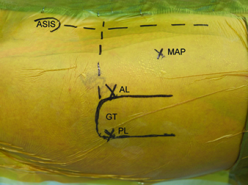
Thorough and precise knowledge of the surface anatomy of the hip is essential for successful hip arthroscopy. Not only does this allow the surgeon to orient portal placement but also ensures adaptability on an individual basis given the wide range of patient’s body habitus. Two bony landmarks are especially important to develop an orientation for portal placement. The anterosuperior iliac spine (ASIS) is the origin of the sartorius as well as the ilioinguinal ligament. Typically a circle is drawn over this palpable landmark. Next, the boundaries of the greater trochanter are outlined. The greater trochanter serves as the insertion point of the tendons of the gluteus minimus, gluteus medius, obturator internus, obturator externus, piriformis, and gemelli.
A longitudinal line is drawn extending from the ASIS with a linear trajectory toward the center of the patella. Two longitudinal lines are drawn distally along the anterior and posterior borders of the greater trochanter, parallel to the axis of the shaft of the femur. Finally, a horizontal line is then drawn from posterior to anterior, intersecting with the proximal tip of the greater trochanter and the vertical line that extends from the ASIS (Fig. 25.1).
The location of the femoral nerve, artery, and vein are then palpated and marked, which traverse anterior and medial to the hip joint, only a few centimeters medial to the planned anterior portal (AP). The femoral nerve is the most lateral of these structures and lies on average 3.2 cm from the AP site (16). Knowledge of the course of the lateral femoral cutaneous nerve (LFCN) should also be kept in the mind of the arthroscopist during creation of the portal incisions. The LFCN exits deep to the ilioinguinal ligament, on average 20 mm (range: 3 to 46 mm) medial to the ASIS (17). The nerve then travels distally, lateral to AP site. The nerve sends out multiple branches, and at the level of the AP is divided into three or more braches (16). The most medial branch of the LFCN lies on average 3 mm lateral to the AP site.
Arthroscopic Portals and Access to the Central Compartment
The surface anatomy previously described in addition to deep structures must be taken into account when creating arthroscopic portals. Prior to any portal placement, the surgeon must ensure proper patient positioning as well as adequate joint distraction to replicate safe access to the compartments in each patient. Previously described portals have been established in areas that not only maximize accessibility to the joint but also minimizing the risk of damaging surrounding structures. Since Byrd’s study of portal placement safety in 1995 (16), approximately 18 portals have been described. The descriptions of some of these portal sites are unclear of the exact anatomical location. Some of these portals were also designed specifically for examination and treatment of the peripheral and peritrochanteric compartments and thus will not be discussed here. We describe the four commonly used portal sites for access and treatment of the central compartment: anterolateral (AL), AP, posterolateral (PL), and midanterior portal (MAP).
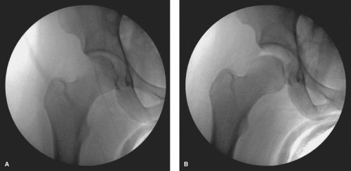
Prior to the creation of the AL portal, one must first ensure adequate joint distraction for safe placement of the cannula, given that it is done without direct intra-articular visualization (Fig. 25.2). Adequate joint distraction has not been specifically studied, but various authors have stated that a “safe” amount of joint distraction to be at least approximately 8 to 10 mm (8,18). The actual force that is required to distract the femoral head from the acetabulum varies on an individual basis, and reports have ranged between 25 and 200 lbs (19). Given that traction is not a benign entity, we recommend performing hip arthroscopy on anesthetized patients with skeletal muscle relaxation. The hip joint also has a resting negative intra-articular pressure, especially during initial distraction. We routinely release this “vacuum effect” with spinal needle puncture followed by injection of saline. Previous studies have shown this to result in a significantly greater joint distention at the same force of joint distraction (6,20).
Anterolateral Portal
The AL portal is commonly the first arthroscopic portal that is created during hip arthroscopy. It is not only useful for direct visualization when creating additional central compartment portals but also is an important arthroscope and working portal for the central compartment. The location for the superficial skin incision is at the junction of the lines that parallel the anterior and the superior aspect of the greater trochanter. Some surgeons prefer to place this incision approximately 1 cm proximal and 1 cm anterior to this intersection point. We prefer to localize the incision with
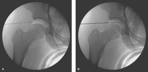
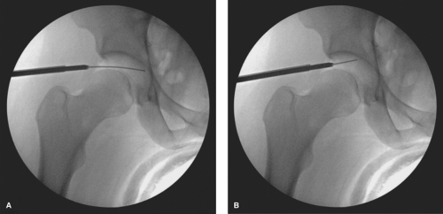
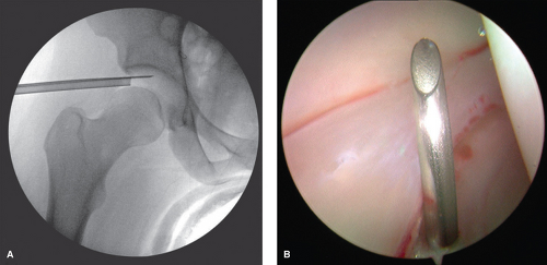
an 18-gauge spinal needle prior to the creation of the incision. The spinal needle is laid over the tip of the greater trochanter with a trajectory aimed toward the distracted space between the acetabulum and the femoral head (Fig. 25.3). The tip of the needle should aim for the distal third of this space, which is verified on fluoroscopy (Fig. 25.3). Once the trajectory and position is accepted by the surgeon, the location of the spinal needle at the lateral thigh is marked. The interval between the gluteus medius and the tensor fascia lata is then palpated and the spinal needle inserted through the skin with an attempt to mimic the previous trajectory toward the hip while aiming approximately 10 to 20 degrees posteriorly. The spinal needle is advanced until piercing through the joint capsule, which can be easily palpated and can again be verified with fluoroscopy (Fig. 25.4A). The trochar of the spinal needle is removed, and the guidewire is inserted through the spinal needle, confirming intra-articular placement by the palpation of the medial wall of the acetabulum, also verified on fluoroscopy (Fig. 25.4B). The guidewire is removed and 30 cc of normal saline is injected into the joint, thereafter allowing passive backflow into the syringe. Usually one can visualize either synovial fluid, or in the case of an irritated hip, blood-tinged fluid. The guidewire is replaced back into the joint, and the spinal needle is removed.
an 18-gauge spinal needle prior to the creation of the incision. The spinal needle is laid over the tip of the greater trochanter with a trajectory aimed toward the distracted space between the acetabulum and the femoral head (Fig. 25.3). The tip of the needle should aim for the distal third of this space, which is verified on fluoroscopy (Fig. 25.3). Once the trajectory and position is accepted by the surgeon, the location of the spinal needle at the lateral thigh is marked. The interval between the gluteus medius and the tensor fascia lata is then palpated and the spinal needle inserted through the skin with an attempt to mimic the previous trajectory toward the hip while aiming approximately 10 to 20 degrees posteriorly. The spinal needle is advanced until piercing through the joint capsule, which can be easily palpated and can again be verified with fluoroscopy (Fig. 25.4A). The trochar of the spinal needle is removed, and the guidewire is inserted through the spinal needle, confirming intra-articular placement by the palpation of the medial wall of the acetabulum, also verified on fluoroscopy (Fig. 25.4B). The guidewire is removed and 30 cc of normal saline is injected into the joint, thereafter allowing passive backflow into the syringe. Usually one can visualize either synovial fluid, or in the case of an irritated hip, blood-tinged fluid. The guidewire is replaced back into the joint, and the spinal needle is removed.
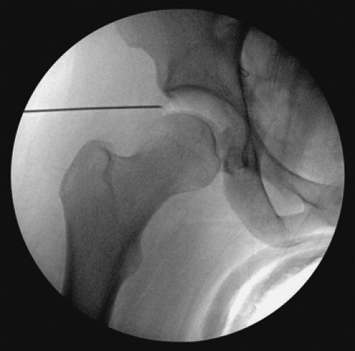 Figure 25.3. Anteroposterior fluoroscopy view of the needle aiming in the appropriate position to assist with the entry point of the anterolateral portal. |
The portal incision is made proximal and distal to the guidewire with an 11-blade while keeping parallel to the previously marked longitudinal reference lines. This incision is made through the skin and the superficial subcutaneous adipose tissue only. A 5-mm arthroscopic cannula with a cannulated sharp trochar is then passed along the guidewire. This is also performed under fluoroscopy, with care to intermittently retract the guidewire to avoid excessive amount within the joint (Fig. 25.5A). The cannula is advanced to the joint capsule, which is penetrated with the sharp trochar. A blunt trochar is then replaced, followed by intra-articular entry of the cannula (Fig. 25.5B). We then follow this with an additional 60 cc of normal saline injected through the cannula.
We prefer to create the AL portal, superficially in the interval between the gluteus medius and the muscle belly of the tensor fascia lata (TFL). In most young active patients, the anterior border of the gluteus medius and the posterior border of the TFL can be palpated, merging in line with the anterior greater trochanter. Utilizing this intermuscular interval, the surgeon avoids the traumatic penetration of the gluteus medius muscle, which would otherwise occur if the skin incision were created at the described 1 cm proximal to the AL corner of the greater trochanter. Avoiding these muscular structures allows the surgeon improved tactile
sensation as the trochar approaches the joint capsule, thus avoiding any unintended plunge into articular surfaces. The superior gluteal nerve is the only true structure of significance relative to the creation of this portal. This nerve exits the greater sciatic foramen, superior to the piriformis, and then travels in the plane between the gluteus medius and the gluteus minimus muscles. There are generally two or three branches and the most caudal one or two branches continue to travel anteriorly to innervate the muscle belly of the tensor fascia lata (21). When the AL portal is placed 1 cm proximal and anterior to the AL angle of the greater trochanter, the superior gluteal nerve is on average 6.4 cm from this portal (22) (Table 25.1).
sensation as the trochar approaches the joint capsule, thus avoiding any unintended plunge into articular surfaces. The superior gluteal nerve is the only true structure of significance relative to the creation of this portal. This nerve exits the greater sciatic foramen, superior to the piriformis, and then travels in the plane between the gluteus medius and the gluteus minimus muscles. There are generally two or three branches and the most caudal one or two branches continue to travel anteriorly to innervate the muscle belly of the tensor fascia lata (21). When the AL portal is placed 1 cm proximal and anterior to the AL angle of the greater trochanter, the superior gluteal nerve is on average 6.4 cm from this portal (22) (Table 25.1).
Posterolateral Portal
The next portal that we prefer to utilize is the PL portal. For a majority of cases, we do not create a true portal, but we rather create an outflow portal using an 18-gauge spinal needle to be left in place during the arthroscopy. This improves visualization of the joint during the diagnostic portion of the arthroscopy, as well as during the creation
of other portal sites. The location for the entry into the skin is at the junction of the lines that parallel the posterior and superior aspect of the greater trochanter. The spinal needle punctures the skin and is advanced toward the joint with a trajectory parallel to the AL portal in the proximal–distal direction and parallel to the floor for the anterior–posterior direction. The tip of the needle should again aim for the distal third of this space between the acetabulum and the femoral head, which can be visualized fluoroscopically (Fig. 25.6A). The entry in the joint can be visualized directly with the arthroscope in the AL portal looking posterior (Fig. 25.6B). Should the surgeon wish to create a formal portal, the trochar of the spinal needle is removed and the guidewire is inserted through the spinal needle, confirming intra-articular placement by direct visualization. The spinal needle is removed and the guidewire left in place. The portal incision is made proximal and distal to the guidewire with an 11-blade while keeping parallel to the previously marked longitudinal reference lines. This incision is made through the skin and superficial subcutaneous adipose tissue only. A 5-mm arthroscopic cannula with a cannulated sharp trochar is then passed along the guidewire, again with care to intermittently retract the guidewire to avoid excessive amount within the joint in a similar manner to the creation of the AL portal. The cannula is advanced to the joint capsule, which is penetrated with the sharp trochar. A blunt trochar is then replaced, followed by intra-articular entry of the cannula.
of other portal sites. The location for the entry into the skin is at the junction of the lines that parallel the posterior and superior aspect of the greater trochanter. The spinal needle punctures the skin and is advanced toward the joint with a trajectory parallel to the AL portal in the proximal–distal direction and parallel to the floor for the anterior–posterior direction. The tip of the needle should again aim for the distal third of this space between the acetabulum and the femoral head, which can be visualized fluoroscopically (Fig. 25.6A). The entry in the joint can be visualized directly with the arthroscope in the AL portal looking posterior (Fig. 25.6B). Should the surgeon wish to create a formal portal, the trochar of the spinal needle is removed and the guidewire is inserted through the spinal needle, confirming intra-articular placement by direct visualization. The spinal needle is removed and the guidewire left in place. The portal incision is made proximal and distal to the guidewire with an 11-blade while keeping parallel to the previously marked longitudinal reference lines. This incision is made through the skin and superficial subcutaneous adipose tissue only. A 5-mm arthroscopic cannula with a cannulated sharp trochar is then passed along the guidewire, again with care to intermittently retract the guidewire to avoid excessive amount within the joint in a similar manner to the creation of the AL portal. The cannula is advanced to the joint capsule, which is penetrated with the sharp trochar. A blunt trochar is then replaced, followed by intra-articular entry of the cannula.
Table 25.1 Relationship of Anatomical Structures to the Central Compartment Arthroscopic Portals | ||||||||||||||||||||||||||||||||||||||||||||||||||||||||||||||||||||
|---|---|---|---|---|---|---|---|---|---|---|---|---|---|---|---|---|---|---|---|---|---|---|---|---|---|---|---|---|---|---|---|---|---|---|---|---|---|---|---|---|---|---|---|---|---|---|---|---|---|---|---|---|---|---|---|---|---|---|---|---|---|---|---|---|---|---|---|---|
| ||||||||||||||||||||||||||||||||||||||||||||||||||||||||||||||||||||
After passing through skin and subcutaneous tissue, the PL portal traverses the gluteus medius and gluteus minimus before reaching the joint capsule. It remains superior and anterior to the piriformis tendon. This portal is generally thought to be the easiest portal to establish, given the relatively thin posterior soft tissue and capsule. The structure that is most at risk is the sciatic nerve, which lies on average 2.2 cm from this portal (22) (Table 25.1). If a spinal needle is used, rather than a true portal, a short intravenous
tube is attached to direct the outflow into the funnel of the arthroscopic drape.
tube is attached to direct the outflow into the funnel of the arthroscopic drape.
Anterior Portal
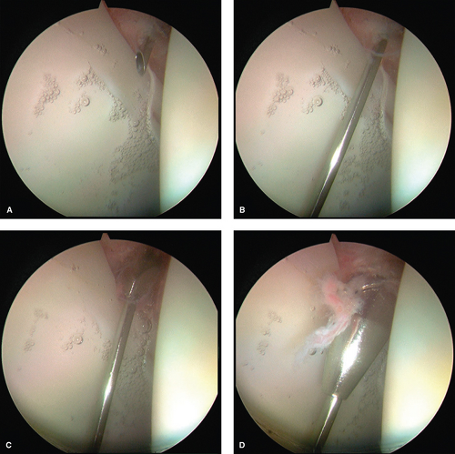
The AP is the next portal that is created and is typically regarded as the most difficult portal to establish. Most surgeons prefer to place this portal at the intersection of the lines drawn distally from the ASIS and transverse line at the tip of the greater trochanter. A portal placed in this location would traverse directly through the tendon of the indirect head of the rectus femoris, which has been suggested to be a source of residual pain due to tendinopathy. Therefore, we prefer to create our AP approximately four fingerbreadths distal and two fingerbreadths lateral to the junction of these intersecting lines (Fig. 25.1). A spinal needle is again used to localize the proper position of the AP. After passing through the skin, the needle is aimed approximately 45 degrees posterior and 20 to 30 degrees toward the midline (Fig. 25.7). The arthroscope is positioned in the AL portal and directed anteriorly to visualize the anterior triangle, which is created by the junction of the femoral head, acetabular labrum, and the top of the field of visualization (Fig. 25.7). The AP should enter this anterior triangle for optimum working utilization. Once the spinal needle enters the joint through the anterior triangle, the spinal needle trochar is removed and the guidewire is threaded into the joint (Fig. 25.8A,B). The spinal needle is removed, the skin is incised proximal and distal to the guidewire with an 11-blade, and a curved hemostat utilized to spread the tissues deep to the incision to avoid injury to the LFCN. The 5-mm arthroscopic cannula with a cannulated sharp trochar is then passed along the guidewire. During the initial insertion through the skin and subcutaneous tissue, the sharp trochar should be slightly retracted within the cannula to avoid sharp injury to the LFCN. The cannula is then advanced to the joint capsule, which is penetrated with the sharp trochar (Fig. 25.8C). A blunt trochar is then replaced, followed by intra-articular entry of the cannula (Fig. 25.8D).
After passing through skin and subcutaneous tissue, the AP traverses the muscle belly of the tensor fascia, followed by the interval between the gluteus minimus and the indirect head of the rectus femoris before reaching the joint capsule. The branches of the LFCN are the structures that are most at risk during the creation of this portal. When the portal is placed 1 cm lateral to the ASIS, the mean distance to the LFCN is 1.5 cm (22) (Table 25.1). Thirty percent of the cadaveric specimens in this study had an LFCN that had branched into two or more branches by the level of the AP. In these cases, the most lateral branch of the nerve was much closer to the AP (0.1, 0.6, and 1 cm). The other structure that is anatomically relevant to this portal is the ascending branch of the lateral circumflex femoral artery (LCFA). On average, this branch terminates 3.1 cm distal to the AP; however, a terminal branch is often seen, which lies on average 1.5 cm away but can be as close as 0.1 cm (22) (Table 25.1).
Midanterior Portal
Kelly and colleagues have anatomically described other portals in addition to the three common portals described above. One additional portal can be used to access the central compartment. This portal site, named the MAP, is localized by first measuring the distance between the anterior and AL portals. By using these two portal sites as vertices, a third portal site is marked distally, such that the three portals serve to form an equilateral triangle. This portal site is created under direct visualization in a similar fashion to the AP. After localization and confirmation with a spinal needle, a guidewire is left in place. The incision is created superficially with an 11-blade followed by spreading of the tissues with a curved hemostat to avoid laceration of the LFCN. Another 5-mm cannula is placed in the hip, first with a sharp trochar until penetration of the hip capsule. Final introduction of the cannula into the joint is done with the blunt trochar in place.
Similar to the AP, the MAP traverses the muscle belly of the tensor fascia, followed by the interval between the gluteus minimus and the indirect head of the rectus femoris before reaching the joint capsule. The LFCN has divided into two or more branches prior to the location of the MAP. The closest branch lies, on average, 2.5 cm from this portal. The closest structure to this portal, however, is the terminal branch of the LCFA, which on average lies 1 cm from the MAP (22) (Table 25.1).
Capsulotomy for Increased Access
The hip capsule is composed of three distinct ligaments that provide additional stability to the hip joint. The ischiofemoral ligament makes up the posterior hip capsule, whereas the iliofemoral and pubofemoral ligaments make up the anterior hip capsule. The ischiofemoral ligament is the thinnest of these ligaments, making arthroscopic portal entry through the posterior hip capsule without much resistance. The pliability of this ligament also allows for more maneuverability with either the arthroscope or other instruments when placed through the PL portal. The pubofemoral ligament, which spans from the anterior–inferior acetabulum
and pubic ramus to the anteromedial femoral neck, does not affect portal establishment for access to the central compartment. The iliofemoral ligament, however, is located anterolaterally, originating from the anterior inferior iliac spine (AIIS) and spreading out to insert at the intertrochanteric line of the anterior femur. The distal aspect of this ligament contains the zona orbicularis, which encircles the femoral neck and has been shown to be one of the most important structures contributing to hip stability in distraction by acting as a locking ring (23). The thickest portion of the iliofemoral ligament is located anteriorly and affects the creation of the anterior and AL portals. The creation of these portal sites is therefore met with higher resistance, and the arthroscopist must control the tendency to plunge with the cannula and thus inadvertently damage intra-articular structures. The location of this ligament also lies in the area of the hip where a majority of pathology is treated arthroscopically. Therefore, an anterior capsulotomy is routinely performed to increase the maneuverability of the arthroscope and instruments within the central compartment.
and pubic ramus to the anteromedial femoral neck, does not affect portal establishment for access to the central compartment. The iliofemoral ligament, however, is located anterolaterally, originating from the anterior inferior iliac spine (AIIS) and spreading out to insert at the intertrochanteric line of the anterior femur. The distal aspect of this ligament contains the zona orbicularis, which encircles the femoral neck and has been shown to be one of the most important structures contributing to hip stability in distraction by acting as a locking ring (23). The thickest portion of the iliofemoral ligament is located anteriorly and affects the creation of the anterior and AL portals. The creation of these portal sites is therefore met with higher resistance, and the arthroscopist must control the tendency to plunge with the cannula and thus inadvertently damage intra-articular structures. The location of this ligament also lies in the area of the hip where a majority of pathology is treated arthroscopically. Therefore, an anterior capsulotomy is routinely performed to increase the maneuverability of the arthroscope and instruments within the central compartment.
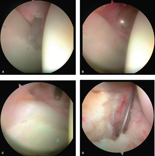
The arthroscope is placed in the AL portal whereas a beaver blade is placed through the AP. The cannula is withdrawn slightly, just outside the capsule whereas the beaver blade remains within the joint. The beaver blade is then used to create a capsulotomy that connects both the anterior and AL portals (Fig. 25.9A). Care is taken to visualize the beaver blade at all times, refraining from allowing the entire blade to move outside of the capsule. The blade is also used in
a levering manner against and incising the capsular tissue. An arthroscopic shaver is then introduced through the AP and the edges of the capsule are debrided, followed by cautery for any bleeding from the capsule (Fig. 25.9B,C). The arthroscope is then moved to the AP to complete the capsulotomy connection to the AL portal in the same fashion with either a beaver blade and/or arthroscopic shaver (Fig. 25.9D). This capsulotomy should allow for sufficient maneuverability of the anterior and AL portals for access and treatment of central compartment disease. Extension of the capsulotomy posteriorly can be performed as needed. A transverse capsulotomy limb may also be performed to create a “T-shaped” pattern to improve visualization of extra-articular structures and thus the peripheral compartment. This will be discussed in a later chapter that is dedicated to discussion of the peripheral compartment.
a levering manner against and incising the capsular tissue. An arthroscopic shaver is then introduced through the AP and the edges of the capsule are debrided, followed by cautery for any bleeding from the capsule (Fig. 25.9B,C). The arthroscope is then moved to the AP to complete the capsulotomy connection to the AL portal in the same fashion with either a beaver blade and/or arthroscopic shaver (Fig. 25.9D). This capsulotomy should allow for sufficient maneuverability of the anterior and AL portals for access and treatment of central compartment disease. Extension of the capsulotomy posteriorly can be performed as needed. A transverse capsulotomy limb may also be performed to create a “T-shaped” pattern to improve visualization of extra-articular structures and thus the peripheral compartment. This will be discussed in a later chapter that is dedicated to discussion of the peripheral compartment.
Arthroscopic Anatomy of the Central Compartment
Capsule
As previously discussed in this chapter, the hip capsule is composed of three distinct ligaments that provide additional stability to the hip joint: the ischiofemoral, iliofemoral, and pubofemoral ligaments. Dvork et al. (9) and later Dienst et al. (24) noted that the iliofemoral ligament and ischiofemoral
ligaments could be identified arthroscopically as thickenings in the capsule; however, individual fibers and specific locations were difficult to specifically delineate. Telleria et al. (25) detailed the relationship of these ligaments to various arthroscopic anatomical points and also described their relationships to commonly created portal sites. Both the anterior and AL portals were noted to pierce the iliofemoral ligament. The AL portal was medial to the lateral border of the iliofemoral ligament whereas the AP was lateral to the medial border. The iliofemoral ligaments generally span between 12:45 and 3 o’clock. The pubofemoral ligament’s lateral border is located near the “psoas-U,” the recess of the anterior acetabulum that corresponds to the trajectory of the more superficial psoas tendon. The medial border of the pubofemoral ligament is located near the junction of the anteroinferior acetabulum and the cotyloid fossa. It generally spans between 3:30 and 5:30. The inferior/medial border of the ischiofemoral ligament is located near the most posteroinferior aspect of the acetabulum (7:45) whereas the superior/lateral border was at the location of the PL portal (10:30). The individual fibers of these ligaments are difficult to discern in patients. The inferior/posterior aspect of the hip in the region of the transverse acetabular ligament and the lateral aspect of the hip are the two major areas of the capsule that are not covered with these important ligaments. On the basis of this study, a routine capsulotomy that is created between the anterior and AL portals traverses the majority of the iliofemoral ligament.
ligaments could be identified arthroscopically as thickenings in the capsule; however, individual fibers and specific locations were difficult to specifically delineate. Telleria et al. (25) detailed the relationship of these ligaments to various arthroscopic anatomical points and also described their relationships to commonly created portal sites. Both the anterior and AL portals were noted to pierce the iliofemoral ligament. The AL portal was medial to the lateral border of the iliofemoral ligament whereas the AP was lateral to the medial border. The iliofemoral ligaments generally span between 12:45 and 3 o’clock. The pubofemoral ligament’s lateral border is located near the “psoas-U,” the recess of the anterior acetabulum that corresponds to the trajectory of the more superficial psoas tendon. The medial border of the pubofemoral ligament is located near the junction of the anteroinferior acetabulum and the cotyloid fossa. It generally spans between 3:30 and 5:30. The inferior/medial border of the ischiofemoral ligament is located near the most posteroinferior aspect of the acetabulum (7:45) whereas the superior/lateral border was at the location of the PL portal (10:30). The individual fibers of these ligaments are difficult to discern in patients. The inferior/posterior aspect of the hip in the region of the transverse acetabular ligament and the lateral aspect of the hip are the two major areas of the capsule that are not covered with these important ligaments. On the basis of this study, a routine capsulotomy that is created between the anterior and AL portals traverses the majority of the iliofemoral ligament.
Labrum
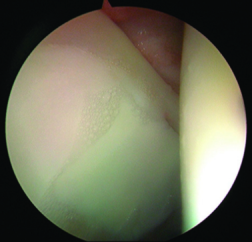
The acetabular labrum is a fibrocartilage structure that surrounds the periphery of the acetabular rim and inferiorly is continuous with the transverse acetabular ligament. The acetabular labrum is classically divided into two parts: capsular and articular. The capsular side of the labrum is composed of dense connective tissue (types I and III collagen), whereas the articular side is composed mainly of fibrocartilage (26). Microscopically, the labrum is composed of three separate layers, which can be distinguished based on the orientation of collagen fibrils. The articular layer is without any orientation whereas the middle layer has fibrils arranged in a lamellar fashion, and the capsular layer oriented in a circular fashion, which is thought to confer stability (26). A wedge-shaped portion of the acetabular rim penetrates into the labral tissue and attaches via a zone of calcified cartilage (27). The labrum is widest anteriorly and has a distinct labral–chondral junction due to a sharp transition zone with minimal fiber interdigitation (27,28). The labral–chondral junction becomes more gradual in the posterior aspect of the hip as fibers from the labrum and acetabular cartilage begin to have significant interdigitation. A physiologic sulcus between the labrum and the acetabular cartilage can therefore be appreciated at the time of arthroscopy (Fig. 25.10). It is important to understand this normal anatomy of the labral–chondral junction as one investigates whether a labral tear is present at the time of arthroscopy.
The acetabular labrum has no intrinsic vasculature. Multiple studies have shown that the majority of blood supply is contributed from the capsular side of the labrum (27,29,30). A recent cadaveric study has shown the blood supply to arise from a series of radial arteries that originate from the periacetabular vascular ring rather than vessels on the capsular surface of within the synovial lining (29). The labrum also may receive vascular contribution from intraosseous penetration, which has been postulated to be the source of neovascularization for labral repairs. There is also evidence that suggests circumferential vessels exist at the labral attachment site on the capsular surface that may also contribute to the labral vascularity (27).
Acetabulum
The acetabulum is a hemisphere with a horseshoe-shaped articular surface and a nonarticular fossa ovalis. The normal acetabulum has approximately 55 degrees of inclination and 20 degrees of anteversion and covers approximately 70% of the femoral head. Switching the arthroscope between the various arthroscopic portals allows full visualization of the articular surface of the acetabulum (Fig. 25.11


Stay updated, free articles. Join our Telegram channel

Full access? Get Clinical Tree


