Fig. 2.1
(a) Radiograph of preoperative fractured hip, (b) radiograph of postoperative left hip repaired by internal fixation screws, and (c) radiograph of an iatrogenic subtrochanteric fracture in association with the screw hole location at the lateral cortex for treatment of avascular necrosis of the femoral head
Occurrence of the iatrogenic subtrochanteric fracture is a highly biomechanical point in nature. It involves the concepts of load, tensile stress generation on the lateral aspect of proximal femur, amplification of stress at holes, and initiation and growth of microcracks under cyclic load as the patient ambulates.
The proximal femoral cortex is one of the most highly stressed regions in the human body. A free body diagram of the proximal femur would show that joint reaction forces at the hip and the abductor muscle force at the greater trochanter act collectively to induce tensile stresses at the screw hole sites. The tension is created indirectly through the moment arms via which the joint forces and muscle forces act. As it will be discussed in this chapter, stress concentration occurs at this region due to the abrupt changes in the shape of the structure and causes increase in local stresses at this area. Since there is an abrupt shape change in the screw hole region compared to the whole femoral shape, the stress concentration emerges from this region which in turn to increases the possibility of iatrogenic subtrochanteric fracture risk.
Amplified stresses, when applied repeatedly, may produce microcracks and other forms of plastic damage in the bone, locally around the screw holes. Normally, these microcracks are repaired by the bone itself in a healthy person and do not cause a sudden bone failure. However, in the situation of reduction in bone quality, these microcracks may gradually accumulate under the cyclic loading which results in progressive damage that may result in a fatigue fracture.
Introduction
Biomechanics is a multidisciplinary field integrating biology and fundamental principles of mechanics for studying various biological systems. In biomechanics, the biological system is idealized as a mechanism or a machine, and a broad range of concepts and laws of mechanics including statics, dynamics, deformable body mechanics, and fluid mechanics are used to analyze various biological concepts. These include native and disease states in biological tissues, mechanism of blood circulation, mechanism of air flow in the lung, and gait. Biomechanics is also an essential aspect of improving medical diagnosis and treatment, as well as designing artificial tissues and implants, as well as medical equipment and devices.
Biomechanics is divided into several applied subfields such as kinesiology, cardiovascular biomechanics, sports biomechanics, computational biomechanics, animal biomechanics, plant biomechanics, and musculoskeletal and orthopedic biomechanics. In general, musculoskeletal/orthopedic biomechanics is concerned with the behavior of musculoskeletal systems and implants under external and internal forces. Musculoskeletal/orthopedic biomechanics is also highly relevant to post-surgery rehabilitation. For example, the applied load is shared between the fracture fixation plate and the healing bone (Fig. 2.2). Material and dimensions of the implant will determine whether stresses in implants and native bone tissue will be well within yield stress of each phase. An overly stiff fracture fixation plate may shield the forces from the healing bone, resulting in reduced bone formation and increased bone resorption around the implant. Therefore, it is essential to predict physiological ranges of forces acting on musculoskeletal tissues during daily activities, and it is also critical to predict the mechanical behavior of musculoskeletal tissues and implants under the forces.
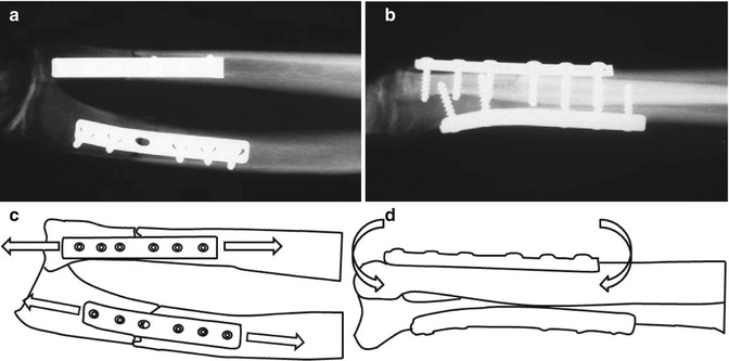
Fig. 2.2
(a–b) Radiography of internal fixation plates on forearm fractures of the radius and ulna. The plates are load-bearing constructs and must withstand (c) tension and (d) bending forces until fracture healing is complete
Basic Concepts, Principles, and Terms
The term of mechanics in biomechanics refers to classical (Newtonian) mechanics. Mass, time, and length are the basic concepts of classical mechanics and are independent of each other. Mass is the amount of matter in an object, and in the International System of Units (SI), its base unit is kilogram (kg). Time is the measure of durations of an event and its base unit is second (sec) in SI. Length is the measure of dimension of an object and its base unit is meter (m) in SI. All other concepts of mechanics, including velocity, acceleration, force, moment (torque), work, energy, stress, strain, etc., are basically derived from these three basic concepts. For example, by definition, velocity is the rate of change of an object’s position over time, and the change in position is measured by length. Therefore, velocity is equal to length divided by time (m/sec in SI). Acceleration is the rate of change of velocity over time. Thus, acceleration is equal to change in velocity divided by time over which the change occurred (m/sec2 in SI).
Before describing the terms and concepts of biomechanics in detail, it is necessary to introduce the meanings of scalar, vector, and tensor concepts. Scalar is a quantity that can be represented by a single number representing magnitude. For example, mass, length, and time are scalar quantities: 10 kg, 5 m, and 15 s. On the other hand, vector is a quantity that requires the knowledge of direction of action besides the magnitude. It is represented by a line segment with an arrow in which the length of the line represents its magnitude, the location of the arrowhead represents its direction, and the angular position of the line represents its orientation. Force and moment are examples of vector quantities. Tensor is an entity that requires magnitude, direction of action, and definition of the area on which the entity is acting. Stress and strain, which will be described in later sections, are tensor quantities.
Force and Moment
A force is defined as a load quantity causing an object to move and change the direction and/or amplitude of its motion or the shape/volume of the object. A force is a vector. The magnitude of force is equal to the mass of an object multiplied by its acceleration:
(2.1)
Therefore, the unit of force in SI is kg.m/sec2 which is also denoted as a Newton (N). Forces can be categorized in various ways based on their orientation to surface, their direction, or their effects on the object. For example, based on their orientation to the surface of an object, forces can be classified as normal or tangential. Normal force acts on a direction which is perpendicular to the area on which the force is acting. Joint contact forces, due to lack of friction, are always normal forces. A tangential force acts within the plane on which it acts. Frictional force is a good example of tangential force since it occurs between two contact surfaces in a direction that is parallel to the surfaces when one surface slides over the other.
Normal forces can be classified as tensile or compressive forces. A tensile force tends to elongate the object along the direction of action of the force, whereas a compressive force tends to shrink the object along the direction of the force (Fig. 2.3b). For example, tendons experience tensile forces predominantly, whereas some bones such as vertebral bodies undergo compressive forces. Weight (or gravitational force) is a form of force that is exerted on the object by the gravitation of the Earth to induce a constant acceleration of 9.8 m/s. Considering a musculoskeletal system, gravitational force is considered as an external force, whereas active tension of muscles, passive tension of a tendon, or joint contact forces are considered as internal forces.
Fig. 2.3
Different loading modes induce different fracture patterns: (a) shear, (b) butterfly fracture resulting from bending, and (c) spiral fracture pattern resulting from torsion. Arrows indicate direction of applied forces or moments
A moment is described as a quantity which causes an object to rotate or distort. One form of moment is the bending moment which imparts tensile and compressive forces on the opposing faces of a long bone (or a fracture fixation plate) (Figs. 2.2b–d and 2.3b). Torque is another form of moment where the moment is applied about the longer axis of a long object in a twisting action (Fig. 2.3c). The magnitude of the moment of a force about a point is equal to the applied force multiplied by the length of the shortest distance between the point and line of action of the applied force, also knowing as lever or the moment arm:

(2.2)
The unit of moment in SI is kg.m2/sec2 which is also called a Newton meter (N-m). A moment or torque is a vector entity and is symbolized by a bold M or T, respectively. The direction of moment (torque) vector can be discerned by the right-hand rule. In this rule, the fingers of the right hand that are curled with the segment of the finger from the knuckles to the tips of the fingers are pointed along the applied force. In this state, the right-hand thumb will point in the direction of the moment (torque) vector.
Rigid Body Mechanics
Musculoskeletal system can be considered as a mechanism or a machine involving an actuator, rigid links, and constraint elements. Therefore, the analyses in the biomechanics are based on two broad branches of the mechanics: rigid body mechanics and deformable body mechanics. Rigid body mechanics itself is divided into two broad categories, statics and dynamics. The basic assumption in both statics and dynamics is that a body is not deformed under applied forces. This kind of body is defined as a rigid body. Actually, this assumption is essential to analyze forces and moments acting on a body so as to calculate unknown forces or moments.
Statics is the field of the mechanics which is concerned with effects of force and moment on a body in equilibrium. Dynamics, on the other hand, is the field of the mechanics which is concerned with effects of force and moment on a change in the motion of a body. Dynamics itself is divided into two subcategories, kinetics and kinematics, which will be described later in this section.
Musculoskeletal biomechanics, and in fact, entire rigid body mechanics, is concerned with forces and motions and is based on three basic laws (Newton’s laws) that govern the relationship between force and motion: (i) if the net force acting upon a body is zero, the body is either at rest or moves in a straight direction with constant velocity; (ii) if the net force acting upon a body is not zero, the body accelerates in the direction of the net force, and the acceleration magnitude is directly proportional to the net force magnitude; and (iii) if a body exerts a force upon a second body, the second body simultaneously exerts a force equal in magnitude, but opposite in direction on the first body [1, 2]. Any type of motion in biomechanics can be explained using the relationship between force and motion.
Newton’s laws rest on two assumptions: physical equilibrium and the conservation of energy. Equilibrium is positioned in the first and second laws, whereas the conservation of energy is positioned in the third law [1, 2]. The equilibrium can be static or dynamic.
Using the description of the first law, if a body is at rest, it is clear that there cannot be any unbalanced applied forces on the body. In this definition, a body that is not moving or a body that is moving at constant velocity is considered to be at rest. Therefore, static equilibrium is a lack of acceleration, not necessarily the lack of motion. This situation is termed as static equilibrium. In static equilibrium, the sum of the forces acting on the body must be zero. The extension of this law is that the sum of the external moments must also be zero for the body to be at rest. This law for static equilibrium can be expressed as
where the symbol Σ is the sum of all forces/moments or net force/moment. These two equations can be applied to all body parts assumed in static equilibrium and used to calculate forces/moments acting on the musculoskeletal systems. Using these equations, the unknown forces/moments in a static equilibrium can be also calculated. For instance, known ground reaction forces and limb weight can be used to predict the joint forces and moments at the knee.
(2.3)
(2.4)
The general approach in static analysis to determine the magnitude and directions of the unknown forces/moments is as follows:
1.
Sketch a free body diagram. Construction of the diagram involves a “virtual dissection” process which isolates the part of the body whose free body diagram is to be constructed.
(a)
When ligaments, tendons, and muscles are “dissected,” they are replaced with tensile forces.
(b)
When the dissection is along a joint articulation surface, a joint reaction force is introduced. The joint reaction force is generally oriented perpendicularly to the joint surface with its line of action directed toward the center of rotation of the joint (e.g., the center of the femoral head, with the femoral head idealized as a hemisphere).
(c)
(d)
If the dissection is performed away from the limb and away from the articulation surfaces, then tensile forces for dissecting muscles and internal reaction forces and moments for dissecting the bone are to be added (see the example of free body diagram in the example below).
2.
Sum of the forces and moments in the x-, y-, and z-axes is equal to zero. In three-dimensional space, these provide six equations using which up to six unknown forces and/or moments can be solved for per diagram. In two-dimensional problems, three equations can be derived: two for force balance in the x- and y-axes and one for moment along the z-axis.
3.
Solve for the unknown forces/moments using linear algebraic equations.
A free body diagram is a simplified drawing of an object including the approximate location, direction, and magnitude of all the forces and moments acting on the object, excluding any flexible joints. For example, the free body diagram of a raised arm holding a dumbbell (Fig. 2.4a) that is detached at the shoulder joint includes gravitational forces due to the mass of the arm and the dumbbell, a joint reaction force on the humerus from the glenoid, and the force of the deltoid muscle contraction (Fig. 2.4b). The anatomical knowledge on the muscle line of actions, muscle attachment points, and bone morphology is useful and needed in constructing the diagram.
Fig. 2.4
(a) Anatomical view and (b) the free body diagram of a raised arm holding a dumbbell that is dissected at the shoulder joint
When a body is not in static equilibrium, the net force on the body cannot be zero, and the body is accelerating along the direction of the net force. A motion herein can be classified as linear (translational), angular (rotational), or general (both linear and angular) motion [2]. Linear motion or translation is the simultaneous movement of all parts of the body by the same distance and in the same direction, such as pushing a block on a horizontal surface. Angular motion is the simultaneous circular movement of all parts of a body by the same angle and in the same direction, such as the example of the thigh during walking that rotates about the hip. In angular motion, the force acts eccentrically to the center of mass (center of rotation) that causes rotation. General motion is the occurrence of both linear and angular motions simultaneously. For example, the lower extremities have both linear and angular motion during walking. The concepts of statics are not valid anymore if a body is accelerating under one or more of these three motions, and the concepts of dynamics begin to apply. In fact, the fundamental concepts of dynamics are space (displacement), time, mass, and force. Velocity, acceleration, torque, moment, work, energy, power, impulse, and momentum are the derived concepts from the fundamental concepts of dynamics.
Dynamics is divided into two subcategories, kinematics and kinetics. Kinematics is concerned with description of the motion of a point, an object, or a system without dealing with forces and torques causing the motion. Kinematic analyses involve the understanding of the relationship between displacement, velocity, and acceleration vectors. Kinetics, on the other hand, is concerned with the analysis of forces and torques that cause the motion. Both kinematics and kinetics are bound by Newton’s second law which is also known as the law of acceleration [2]. The law states that if the net force acting upon a body is not zero, a body accelerates in the direction of the net force, and the acceleration magnitude is directly proportional to the net force magnitude. Using this description in the second law, if a body is not in static equilibrium, it is clear that there is at least one unbalanced applied force on the body that causes the motion. The extension of this law is that the sum of the external moments is not zero if the body has a motion. This situation is described by dynamic equilibrium. The law for dynamic equilibrium then can be expressed in the following equations:
where m is the mass of a body, a is the acceleration of the center of mass, I is the moment of inertia that is the distribution of mass about the center of rotation and is dependent on the shape of the body, and α is the angular acceleration (radian/sec2 in SI unit). These two equations can be applied to all body parts assumed in dynamic equilibrium and used to calculate forces/moments acting on the musculoskeletal systems. Using these equations, the unknown forces/moments in a dynamic equilibrium can also be calculated. The general approach in dynamic analysis is to determine the magnitude and directions of unknown variables in the following:
(2.5)
(2.6)
1.
Sketch a free body diagram, and indicate correct directions of all known forces, moments, or accelerations. If the direction of them is not known, it can be then assumed as positive direction.
2.
Choose convenient coordinate systems such as the Cartesian or polar coordinates.
3.
Apply the equations of motion, and solve for the unknown variables.
4.
If the result appears with a negative value, it means that the originally chosen directions are to be reversed.
Using the equation of motion (Newton’s second law) for kinetic characteristic of a body is convenient if the applied forces or moments are constant. However, the solution of the equations sometimes may be difficult and complex in terms of having no constant force and moment. In such a situation, the concepts of work and energy can be applied to solve this kind of complex problem.
Work is defined as a quantity of force required to move an object through a distance or is the product of a force that is corresponding to displacement. Work is a scalar quantity, and the work done by a constant force is equal to the magnitude of the force multiplied by the displacement moved in the direction of the force:
(2.7)
The work done by a force that is changing with time, on the other hand, can be calculated as the integral of the force over the distance applied:
(2.8)
Therefore, the standard unit of work in SI is kg.m2/sec2 which is also called a Newton meter (N-m) or joule (J). For a force to do work, a body must have a displacement. Moreover, work done by force can be positive or negative. For example, if a force applied on a body has the same direction of displacement, the work done by the force is positive. However, if the force and displacement have opposite directions as in the example of a frictional force, the work done by the frictional force is negative.
< div class='tao-gold-member'>
Only gold members can continue reading. Log In or Register to continue
Related posts:

Stay updated, free articles. Join our Telegram channel

Full access? Get Clinical Tree


