Functional Anatomy of the Foot and Ankle


Functional Anatomy of the Foot and Ankle


Shahan K. Sarrafian

Armen S. Kelikian


TERMINOLOGY OF MOTION

Until a consensus is reached, we will use the triaxial orthogonal coordinate system X-Y-Z of the human body and of the leg and its transposition into the foot to provide the basis for a sound definition of the movements occurring at the foot-ankle complex. The clinical terminology is well entrenched and will be preserved as long as we refer also to the coordinate system understood by all. Some undeniable difficulties still persist at the level of the foot when function is defined relative to the long axis of the foot passing from the heel through the second metatarsal and second toe. For example, the terms metatarsus primus varus and hallux valgus describe correctly the position of the segments relative to the sagittal mid plane of the body, whereas the contradiction is apparent when one labels, for example, the abductor hallucis and the adductor hallucis muscles. Factually, the abductor hallucis muscle is an adductor and the adductor muscle is an abductor of the hallux. Such contradiction, however, does not exist in the French anatomic studies.

The rationale of the transposition of the leg-ankle coordinate of motion to the foot axes is seen when one considers the embryologic evolution of the foot.1 Initially, the foot is axially aligned with the leg and the three orthogonal coordinates of the leg-foot are the same with a transverse, vertical, and longitudinal axis of motion. As the embryo foot makes its first 90 degrees of rotation relative to the leg, the transverse axis of the foot remains unchanged, whereas the longitudinal axis of the foot generates the same type of motion as the vertical axis of the leg-ankle; the vertical axis of the foot generates the same type of motion as the longitudinal axis of the leg-ankle (Fig. 10.1). This concept of Huson’s facilitates the integration of the terminology of motion. However, on a habitual and clinical basis we will still use some commonly accepted terms such as supination and pronation (in parallel with intracarpal supination-pronation between the first and second carpal rows of the wrist) and valgus and varus (because these may well be present in a dynamic fashion in clinical entities and correspond well to the standard axis references of the body-leg). We have some difficulty accepting as a functional component of inversion a motion of inversion (adductioninversion, plantar flexion) or eversion as a component of eversion (abduction-eversion, dorsal flexion), as expressed by Huson.1

The use of supination-pronation (adduction-supinationplantar flexion; abduction-pronation-dorsal flexion) obviates this terminologic difficulty. Furthermore, we will also preserve the terminology of hindfoot and forefoot, which presents descriptive facility from the clinical point of view.

Each axis of the orthogonal coordinate system generates a rotary motion occurring in a plane perpendicular to the axis as follows:


Transverse axis X generates motion in the sagittal plane.

Vertical axis Y generates motion in the transverse or horizontal plane.

Longitudinal axis Z generates motion in the frontal or coronal plane.

The types of motion occurring around the X, Y, and Z axes are as follows:

Tibiotalar (Fig. 10.2)

Transverse axis X: dorsiflexion or extension and plantar

flexion or flexion in the sagittal plane Vertical axis Y: internal rotation, external rotation in the

transverse plane Longitudinal axis Z: adduction-abduction of the talus or supination-pronation of the talus or lateral-medial talar tilt The motions around the Y, Z axes are secondary.

Motion of the foot plate (talocalcaneonavicular, midtarsal, tarsometatarsal) around the talus (see Fig. 10.2).

These motions occur around the obliquely oriented and movable axes, but they can be converted into their vectorial orthogonal components X, Y, Z.

Transverse axis X: dorsiflexion, plantar flexion in the sagittal plane. Vertical axis Y: abduction-adduction in the transverse or horizontal plane

Longitudinal axis Z: supination in the frontal plane or counterclockwise rotation on the right and clockwise rotation on the left when facing the foot in an anteroposterior direction. The medial border of the foot is elevated. Pronation in the frontal plane or clockwise rotation on the right and counterclockwise rotation on the left when facing the foot in an anteroposterior direction. The lateral border of the foot is in elevation. The motion around this axis may also be termed internal-external rotation, endorotationexorotation, or, by some, inversion-eversion.


AXIS OF MOTION: FIXED VERSUS MOBILE, SINGLE VERSUS MULTIPLE

The axis of motion is the imaginary line around which the motion occurs. An inclined axis is reduced vectorially to its three components in the orthogonal coordinate system, thus

generating motion in three planes, with predominance of the planes of motion in function of the magnitude of the corresponding vectorial component.


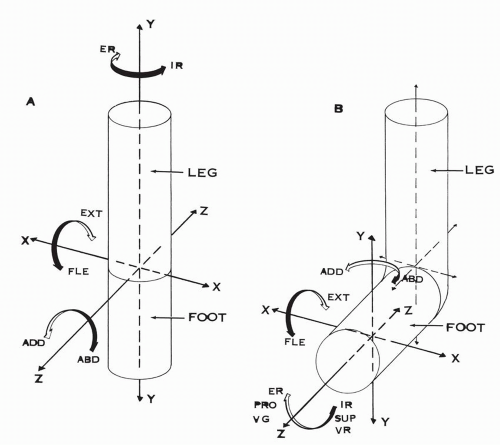
Figure 10.1 (A) Axes of motion in the foot and leg of the embryo: the foot is aligned with the leg. (B) Axes of motion in the fetus with the foot at right angle to the leg. (ER, external rotation; IR, internal rotation; EXT, extension; FLE, flexion; ABD, abduction; ADD, adduction; PRO, pronation; SUP, supination; VG, valgus; VR, varus.) The vertical axis of ER, IR of the leg is now the longitudinal axis of ER, IR of the foot. The longitudinal axis of ABD, ADD of the leg is now the vertical axis of ABD, ADD of the foot. The transverse axis of FLE, EXT remains unchanged.


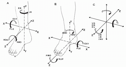
Figure 10.2 (A) Axes of motion of the ankle and leg. YY axis of ER, IR of the leg-talus. XX′ axis of FLE, EXT of the talus. ZZ axis of ASD, ADD of the talus. (B) Axes of motion of the foot plate. YY axis of ADD, ABD, XX axis of FLE, EXT. ZZ axis of SUP, PRO. (C) Different terminology used for the motion around the longitudinal axis ZZ, VG, ER, EV and VR, IR, INV. (ER, external rotation; IR, internal rotation; FLE, flexion; EXT, extension; ASD, abduction; ADD, adduction; VG, valgus; VR, varus; EV, eversion; INV, inversion.)

The concept of triplane motion is now firmly established with the recent biomechanical investigations of Ambagtsheer,2 Van Langelaan,3 Benink,4 and Lundberg and colleagues.5, 6, 7 Furthermore, the concept of a fixed axis of motion has evolved toward the instantly moving axis of motion with accompanying helical motion, introducing the concept of rotation combined with translation around the axis.1 Huson, in the early 1960s, challenged the concept of a fixed axis functioning like hinges8 and Van Langelaan concluded that “movements are found to take place around an axis which moves continuously and the position of which could be approximated with the aid of a bundle of discrete helical axes.2


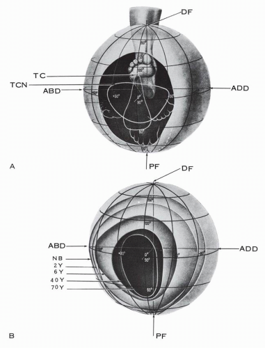
Figure 10.3 Field of motion of the foot-ankle complex. With aging, there is transverse constriction of the field of motion. (A) Oval contour of the field of motion. (B) Field of motion in different age groups. (TC, field contribution of talocrural joint; TCN, field contribution of talocalcaneonavicular joint; DF, dorsiflexion; PF, plantar flexion; ABD, abduction; ADD, adduction; NB, newborn; 2Y, 2 years old; 6Y, 6 years old; 40Y, 40 years old; 70Y, 70 years old.) (Adapted from Lang J, Wachsmuth W. Praktische Anatomie: Ein Lehr- und Hilfsbuch der anatomischen Grundlagen ärztlichen Handelns, Vol 1, Part 4. Berlin: Springer-Verlag; 1972:370.)


FIELD OF MOTION

The functional capacity of the foot and ankle is expressed by the contour and dimensions of its field of motion (Fig. 10.3).9 The dimensions of the field of motion include all possible spatial displacements of the forefoot, with the distal leg remaining stationary. The field of motion of the foot and ankle is oval in contour. The vertical segment of the field is determined mainly by the talocrural joint and the transverse segment by the foot plate.
The functional capacity of the foot and ankle is age dependent. The functional field is the largest in the newborn and it gradually constricts with aging, more in the transverse segment than in the vertical. At age 2 to 6 years, the field is transversely oval; at age 40 it is converted into a high oval; and, by age 70, it is narrow, limited mainly to the vertical segment.8 In terms of functional capacity, the foot at age 70 years can dorsiflex and plantarflex but has a limited capacity to adapt to walking on uneven ground.


ANKLE JOINT


Axis of Motion


Single Axis of Motion

According to Inman, the empirical axis of the ankle joint passes slightly distal to the tips of the malleoli at 5 mm ± 3 mm (range, 0 to 11 mm) distal to the tip of the medial malleolus and 3 mm ± 2 mm (range, 0 to 12 mm) distal to and 8 mm ± 5 mm anterior to the tip of the lateral malleolus.10 The axis is inclined downward and laterally in the frontal plane (Fig. 10.4) and is rotated posterolaterally in the horizontal or transverse plane (Fig. 10.5).

In the frontal plane, the angle between the empirical axis of the ankle and the midline of the tibia is 82.7 degrees ± 3.7 degrees, with a range of 74 to 94 degrees (Fig. 10.6).10 In the transverse plane, the angle of the ankle axis with the transverse axis of the knee is 20 to 30 degrees.10


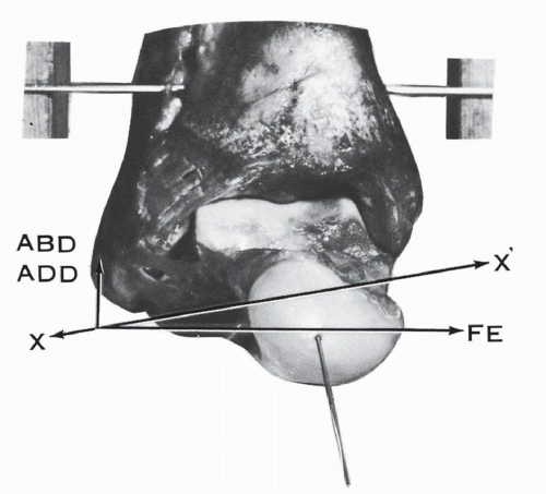
Figure 10.4 Axis of the ankle joint. The axis of the ankle joint XX is inclined as indicated and has two vectorial components: the major transverse component, which generates the motion of flexion-extension (FE), and the lesser vertical component, which generates the motion of the abduction-adduction (ABD-ADD).


Multiple Axes of Motion

Barnett and Napier11 and Hicks12 recognize two axes to the ankle joint: a dorsiflexion axis inclined downward and laterally and a plantar flexion axis inclined downward and medially (Fig. 10.7). The changeover occurs within a few degrees of the neutral
position of the talus (Figs. 10.8 and 10.9). Barnett and Napier11 based their conclusions on the determination of the curvatures of the lateral and medial marginal profiles of the talar trochlea. The center of the curvature being the axis of motion, the lateral profile is “almost always an arc of a true circle and in all positions of the talus the axis of rotation must pass through the center of this circle.’11 The medial profile is formed by the arcs of two circles with different radii. The arc of a small circle, occupying the anterior one third of the medial profile, corresponds to the dorsiflexion arc; the center of the circle is high in location. The arc of a large circle, occupying the posterior two thirds of the medial profile, corresponds to the plantar flexion arc; the center of the circle is low in location.


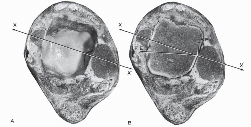
Figure 10.5 Cross-section of the ankle 2 cm above the tip of the medial malleolus, indicating the oblique orientation of the axis of motion of XX′ of the ankle in the transverse plane. The axis XX has a major transverse component for flexion-extension (FE) and a minor longitudinal component for supination-pronation (SP). (A) Cross-section demonstrating the two malleoli and the tibial plafond. (B) Cross section with the dome of the talus lodged in the ankle mortise.


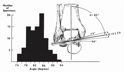
Figure 10.6 Variations in the angle between the midline of the tibia and the empirical axis of the ankle. This histogram reveals a considerable spread of individual values. (Inman TV. The Joints of the Ankle. Baltimore: Williams & Wilkins; 1976:27.)

Lundberg and colleagues analyzed the axis of the talocrural joint by roentgen stereophotogrammetry in eight healthy human volunteers.13 Tantalum beads, 0.8 mm in size, were inserted in their corresponding bones as markers. Under full weight bearing, for each individual, the foot was carried by the supportive platform from 30 degrees of plantar flexion to 30 degrees of dorsiflexion in increments of 10 degrees. The helical axis for each pair of consecutive positions was determined. Their investigation “fully supports the findings of Barnett and Napier and Hicks that the talo-crural joint uses different axes for plantar flexion and dorsi-flexion.”13 Based on their data, the mean inclinations of the axes in the eight subjects were as follows, with 0 degrees corresponding to a horizontal axis: negative (—) corresponding to an axis inclined downward in a medial direction and positive (+) corresponding to an axis inclined downward laterally (Fig. 10.10).


Plantar Flexion

30-20 degrees 20-10 degrees 10-0 degrees


Inclination of Axis

— 12 degrees

— 8.25 degrees + 8.25 degrees


Dorsiflexion

0-10 degrees 10-20 degrees 20-30 degrees

+ 15.5 degrees + 18.87 degrees + 22.5 degrees

When projected onto a horizontal plane, the axes passed through the malleoli (Fig. 10.11).

Sammarco and coworkers studied the instant centers of rotation and surface velocities at the point of contact in 24 normal weight-bearing ankles and six non-weight-bearing ankles.14 In the weight-bearing group, the locations of the instant centers of rotation were as follows: 12 ankles, within the body of the talus; 8 ankles, one or two centers below the body of the talus; 2 ankles, above the joint surface; and 2 ankles, on the joint surface. In the six non-weight-bearing ankles, there was also scattered distribution of the centers of rotation. The motion pattern from plantar flexion to dorsiflexion was distraction of the joint surfaces at the beginning, sliding throughout the arc of motion, and jamming of the joint surfaces at the end of the motion (Fig. 10.12).


Range of Motion

Dorsiflexion and plantar flexion are the major components of the motion at the talocrural joint. The minor components are the rotations around the vertical and the longitudinal axes.

The range of ankle flexion-extension is variable. The methodology used—clinical, roentgenographic, anatomic (cadaveric)— accounts for some of the reported discrepancies.

The reported normal ranges of motion at the ankle joint are shown in Table 10.1. During the stance phase of the gait, the ankle motion, as reported by Stauffer and colleagues, is 24.4 degrees in average (range, 20 to 31 degrees), with 10.2-degree dorsiflexion (range, 6 to 16 degrees) and 14.2-degree plantar flexion (range, 13 to 17 degrees).15 Motion around the vertical axis, external-internal rotation of the talus, occurs at the ankle joint. Close16 and Close and Inman17 report a range of 5 to 6 degrees of external rotation of the talus (relative to the tibia) as active or passive dorsiflexion takes place at the ankle and “this rotation is reversed as the ankle is plantar flexed.” Close also mentions 5 to 6 degrees of horizontal rotation occurring at the ankle joint during the stance phase of walking.


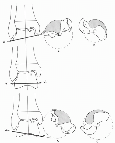
Figure 10.7 Ankle joint axis variation. In dorsiflexion (DF), the axis of motion XX′ is inclined downward and laterally. In plantar flexion (PF), the axis of motion ZZ′ is inclined downward and medially. Near neutral (N), the axis of motion YY′ is almost horizontal. The lateral trochlear contour (A) is an arc of a true circle. The medial trochlear contour is more complex. Its anterior third or dorsiflexion arc (B) belongs to a smaller circle as compared with the posterior two thirds or plantar flexion arc (C), which belongs to a large circle. (Adapted from Barnett CJ, Napier JR. The axis of rotation at the ankle joint in man: Its influence upon the form of the talus and the mobility of the fibula. J Anat. 1952;86:1.)


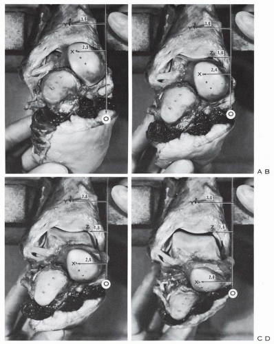
Figure 10.8 Ankle and hindfoot specimen. Tibia and fibula are stabilized. The talus is carried from dorsiflexion (A) to neutral (B) and plantar flexion (C,D). A vertical reference line O is traced. The distance of the tibial reference points Y and Z from the line O remains constant (3.6 cm and 1.6 cm). A drill point X is taken as a reference point on the talar head. The distance from point X to the vertical reference line O is measured in all four positions: dorsiflexion distance, 2.5 cm; neutral distance, 2.4 cm; plantar flexion distance, 2.6 cm; maximum plantar flexion distance, 2.8 cm. The data indicate that, in this specimen, during dorsiflexion the talus is displaced upward and laterally around an oblique axis inclined downward and laterally. In neutral the axis is transverse, whereas in plantar flexion the axis is inclined downward and medially as the talar reference point is displaced downward and laterally.


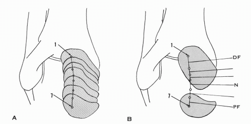
Figure 10.9 (A) Tracings of the displacements of the talar head reference point from dorsiflexion (1) to plantar flexion (7). (B) Motion axes drawn, perpendicular to the displacement lines. The axis is inclined laterally and downward in dorsiflexion and medially and downward in plantar flexion. The changeover in direction occurs very close to the neutral position of the ankle. (DF, dorsiflexion; N, neutral; PF, plantar flexion.)


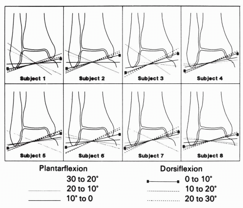
Figure 10.10 Discrete helical axes of the talocrural joint of each subject from each 10-degree interval from 30 degrees of plantar flexion to 30 degrees of dorsiflexion projected onto a coronal plane. All plantar flexion axes are more horizontal, or inclining downward and medially, than are the dorsiflexion axes. (Lundberg A, Svensson OK, Nemeth G, et al. The axis of rotation of the ankle joint. J Bone Joint Surg Br. 1989;71 [1]:94.)


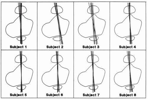
Figure 10.11 Discrete helical axes of the talocrural joint projected onto a horizontal plane. Axes tend to fall parallel to a transverse plane through the malleoli. (Lundberg A, Svensson OK, Nemeth G, et al. The axis of rotation of the ankle joint. J Bone Joint Surg Br. 1989;71 [1]:94.)

McCullough and Burge, in an experimental setup, applied a rotary torque of 3 N · m on the talus about a vertical axis and measured the horizontal talar rotation under variable degrees of vertical load.18 At a minimum load of 9.8 N (1 kg), the mean range of horizontal talar rotation was 24.1 degrees. With increasing load from 9.8 N (1 kg) to 490 N (50 kg), the horizontal rotation decreased in a linear fashion for a total value of 7.5 degrees ± 1.5 degrees (Fig. 10.13). The range of rotation was nearly the same in plantar flexion and dorsiflexion.

Lundberg and colleagues, using the roentgen stereophotogrammetric technique described previously, analyzed the horizontal rotation of the talus in eight healthy volunteers.5 From 0 to 30 degrees of dorsiflexion there was a consistent pattern of increasing external rotation, which reached 8.9 degrees. From 0 to 10 degrees of plantar flexion there was a minimal amount of internal rotation (1.4 degrees ± 0.9 degrees) followed by a minimal amount of external rotation (0.6 degrees ± 3 degrees) at 30 degrees of plantar flexion (Fig. 10.14).

A small amount of consistent supinatory rotation of the talus around the longitudinal axis was also recorded as the foot moved from 30 degrees of plantar flexion to 30 degrees of dorsiflexion.

Lundberg and colleagues, using the same methodology, studied the talar motion during rotation of the leg under weight-bearing conditions.7 With external rotation of the leg from 0 to 10 degrees, the talus moved triaxially, with dorsiflexion of 4.3 degrees ±3.5 degrees, minimal supination of 1.5 degrees ±1.6 degrees, and external rotation of 0.7 degrees ± 2.5 degrees. When the leg turned internally 20 degrees, the talus rotated externally 5.0 degrees ±2.0 degrees, with associated minimal pronation of 0.7 degrees ±0.5 degrees and a trace of plantar flexion of 0.1 degrees ±1.9 degrees.

From dorsiflexion to plantar flexion at the ankle joint, the articular surfaces of the talus and the malleoli remain in contact. Considering that the superior talar surface is larger anteriorly than posteriorly, with an average difference of 4.2 mm (2 to 6 mm), the question of potential “play” of the talus in the ankle mortise at full plantar flexion is raised. This, however, does not occur. In full plantar flexion, the posterior two thirds of the talar dome remains in the ankle mortise (Fig. 10.15), thus minimizing the potential difference between the transverse diameter of the talus and the bimalleolar transverse distance. Furthermore, Inman, in a study of 86 tali, demonstrated that the trochlea of the talus “is a section of a frustum of a cone and not of a cylinder.”10 The apex of the cone is medial, with the conical angle of the frustum at 24 degrees ± 6 degrees (range, 10 to 40 degrees) (Fig. 10.16). In addition, Close and Inman made transverse saw marks across the trochlear surface of the talus along the frontal plane of the distal tibia throughout the range
of plantar flexion and dorsiflexion of the ankle.17 The markings were not parallel and converged toward a point 10.6 to 12.7 cm (4 to 5 inches) medial to the ankle joint and the talar trochlea offered at any time to the bimalleolar fork not the transverse dimension but a larger and constant generating line of the truncated cone (Fig. 10.17). The potential play of the talus in plantar flexion is thus absent.


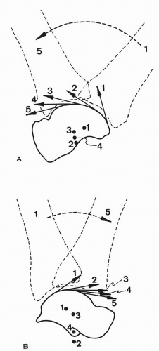
Figure 10.12 Instant centers of rotation and surface velocities from plantar flexion (1) to dorsiflexion (5) in the ankle. (A) Nonweight-bearing: the instant centers of rotation are located in the talus. The surface velocities indicate joint distraction at the beginning of motion, followed by sliding. (B) Weight bearing: an instant center of rotation may be located below the talus. The surface velocities indicate also distraction, followed by sliding. Compression or jamming may occur in maximum dorsiflexion. (Sammarco JG, Burstein AH, Frankel VH. Biomechanics of the ankle: A kinematic study. Orthop Clin North Am. 1973;4[1]:75.)


TABLE 10.1 REPORTED NORMAL RANGES OF ANKLE JOINT MOTION


Range of Motion


Author


Dorsiflexion (extension)


Plantar Flexion


AAOS


18 degrees


48


Bonin


10 to 20 degrees


25 to 35


Weseley and coworkers


0 to 10 degrees (maximum, 23 degrees)


26 to 35 degrees (minimum, 10 degrees; maximum, 51 degrees)


Sammarco and coworkers


Weight bearing


21 degrees ± 7.21 degrees


23 degrees ± 8 degrees


Non-weight-bearing


23 degrees ± 7.5 degrees


23 degrees ± 9 degrees


Boone and Azen (clinical measurements)


12.6 degrees ± 4.4 degrees


56.2 degrees ± 6.1 degrees


The functional implication of the segmental conical contour was correlated with the inescapable triplanar motion of the talus by Bremer.19 Plantar flexion of the talus induces a functional varus or supination.

Barnett and Napier correlated the wedge contour of the talus with its potential for internal rotation.11 During plantar flexion, the medial talar surface has a tendency to separate from the diverging medial malleolar surface, but this is neutralized by the synchronous internal rotation of the talus, which is possible only through the wedge contour of the talar trochlea, narrower posterolaterally. Furthermore, Barnett and Napier associated the degree of posterolateral wedging of the talar trochlea with the inclination of the plantar flexion axis of the ankle joint.11 Increased inclination of this axis corresponded to marked wedging of the talus, and a minimum inclination corresponded to a minimum wedging. With a near horizontal plantar flexion axis, the talar medial and lateral surfaces were nearly parallel.


Mobility of the Fibula and Tibiofibular Syndesmosis

Poirier and Charpy20 described the tibiofibular mortise as elastic, accommodating the dimensions of the articular surface of the talus, and securing the contact between the articulating surfaces in all positions. Dorsiflexion of the foot presents the larger talar surface to the mortise. To accommodate, the fibula moves apart, the inferior tibioperoneal ligaments are tense, and the large synovial fringe located in the posterior cleft of the synostosis reenters the peroneo-tibial interline. On the contrary, in plantar flexion, the narrower posterior part of the talar surface is presented to the tibiofibular mortise. The fibula approaches


the tibia. The inferior peroneo-tibial ligaments are relaxed and the synovial fringe is expulsed from the peroneo-tibial interval and appears in the external angle of the mortise.


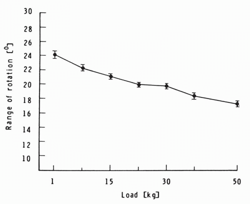
Figure 10.13 Mean range of horizontal talar medial rotation with a rotary torque of 3 N*m under variable degrees of vertical load. The horizontal talar rotation decreases with increased vertical load. (McCullough CJ, Burge PD. Rotary stability of the load-bearing ankle. An experimental study. J Bone Joint Surg Br. 1980;62[4]:460.)


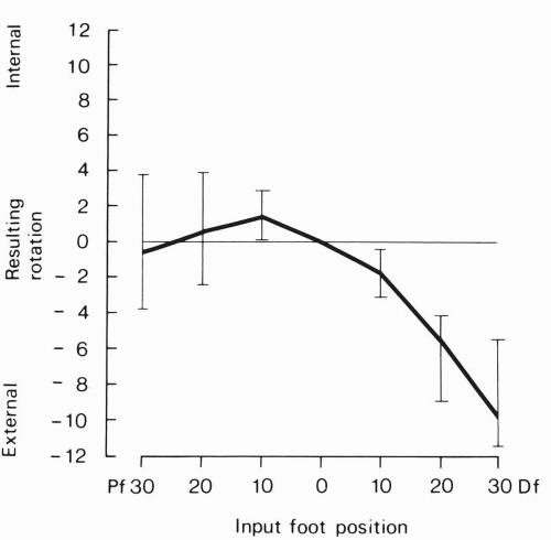
Figure 10.14 Horizontal rotation of the talus around the vertical axis at different dorsiflexion-plantar flexion input of the ankle-foot. (Lundberg A, Goldie I, Kalin BO, et al. Kinematics of the ankle/foot complex. Plantar flexion and dorsiflexion. Foot Ankle. 1989;9[4]:194.)


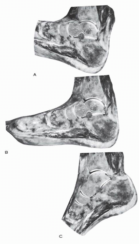
Figure 10.15 Sagittal cross-section of the hindfoot, indicating that in (A) full dorsiflexion, (B) neutral position, and (C) full plantar flexion, the articular surface of the tibia covers two thirds of the talar articular surface. At no time in plantar flexion is the narrower posterior third of the talus occupying the entire ankle mortise.


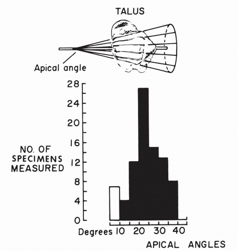
Figure 10.16 Variations of the apical angles of the conical surface of the talar trochlea obtained by extending directions of saw cuts toward the medial side. (Inman TV. The Joints of the Ankle. Baltimore: Williams & Wilkins; 1976:23.)


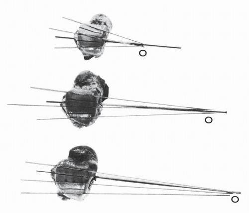
Figure 10.17 The trochlear surface of the talus is a truncated cone. The talus is carried from full dorsiflexion to full plantar flexion, and at each interval a saw cut is made on the trochlear surface along the anterior tibial articular margin. The serial saw cuts are not parallel but converge to the apex O of the cone, as demonstrated in the three tali. (Inman TV. The Joints of the Ankle. Baltimore: Williams & Wilkins; 1976:21.)

During dorsiflexion at the ankle from the plantar-flexed position there is, as reported by Close, an increase in the intermalleolar distance of approximately 1.5 mm (1 to 2 mm) and lateral rotation of the fibula in the horizontal plane, relative to the tibia, of 2.5 degrees.16 There is also an associated lateral rotation of the talus of 4 degrees relative to the tibia (Fig. 10.18). Barnett and Napier correlated the mobility of the fibula at the proximal tibiofibular joint with the inclination of the dorsiflexion axis of the ankle joint.11 In a study of 152 specimens, they classified the proximal tibiofibular joint into three types.


Type I (27%): There is a large, nearly circular, horizontal articular surface on the tibia, measuring more than 20 mm2, with an inclination to the horizontal of less than 30 degrees.

Type II (26%): The articular surface is moderately larger and elliptical and communicates frequently with the knee joint through the synovial bursa deep to the popliteus tendon.

Type III (28%): The articular surface is small (<15 mm2), irregular, and steeply inclined to the horizontal (an inclination angle of more than 30 degrees to the horizontal).

The remaining 19% could not be classified.


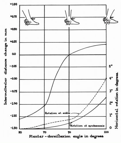
Figure 10.18 Rotation at the ankle and at the syndesmosis and the changes in the intermalleolar distance on dorsiflexion of the foot. (Close JR. Some applications of the functional anatomy of the ankle joint. J Bone Joint Surg Am. 1956;38[1]:771.)

A type I proximal articular surface of the fibula provided more mobility and corresponded to the maximally inclined dorsiflexion axis of the ankle joint. The minimally inclined axis correlated with the type III or the relatively immobile fibula.

Kärrholm and colleagues measured the fibular displacement at the ankle joint from plantar flexion to dorsiflexion in nine children and adolescents using roentgen stereophotogrammetric analysis with intraosseous embedded metal markers.21 The distal fibular translation was measured along the three orthogonal coordinates. The total average lateral displacement of the distal fibula was 1.4 mm (0.5 to 2.4 mm) when the ankle moved from plantar flexion to dorsiflexion. The largest width of the mortise was observed at maximum dorsiflexion of the ankle. Fibular translation occurred along the sagittal axis. The anterior translation (0.1 mm) from plantar flexion to neutral and the posterior translation (0.7 mm) from neutral to dorsiflexion were minimal. The translation along the vertical axis is also reported as a minimal (0.5 mm) distal displacement of the fibula during the same arc of motion. Most of the analyzed ankles demonstrated a posterolateral displacement of the distal fibula.

Weinert and coworkers described a downward and lateral motion of the fibula during the strike phase of running.22 The dynamic study was performed with motion-picture studies of athletes running barefoot on a football field. This was supplemented by a cineroentgenographic study of subjects running on an x-ray table. This dynamic fibular functional study was further expanded by Scranton and colleagues.23 A distal shift of the fibula averaging 2.4 mm was measured radiographically in ten ankles with weight bearing, with shift of the weight to the forefoot simulating initiation of push-off. The fibular descent was explained on the basis of the downward pull exerted by the flexors of the foot.

In 25 fresh frozen cadaver specimens, Xenos et al.24 investigated the role of the syndesmotic ligaments when the ankle was loaded with external rotation torque (5 Nm) with the foot held in neutral flexion. The syndesmotic ligaments were incrementally sectioned and direct measurements of anatomic diastasis were made.

A mean diastasis of 2.3 mm (range 0.5 to 4.0 mm) occurred when the anterior tibiofibular ligament was sectioned. With the additional sectioning of the interosseous ligament, an additional increase of 2.2 mm in the mean diastasis was seen. With the
additional sectioning of the posterior tibiofibular ligament, the total diastasis was 7.3 mm (range, 3.0 to 15.5 mm). The findings with regard to the degree of rotation paralleled those regarding distasis. The mean external rotation increased 2.7 degrees after the anterior tibiofibular ligament was cut. The mean total increase in rotation was 10.2 degrees when all three ligaments were sectioned.


TABLE 10.2 CONTACT AREAS IN INTACT SPECIMENS


Average Area (cm2 )


Author


Neutral


Plantar Flexion


Dorsiflexion


Macko (1991)


5.22 ± 0.94a


3.81 ±0.93 at (15 degrees)a


5.40 ±0.74 at (10 degrees)a


Paar (1983)


4.15


4.15 at (10 degrees)


3.63 at (10 degrees)


Ramsey and Hamilton (1976)


4.40 ± 1.21a


3.69 at (20 degrees)


Kimizuka (1980)


4.83


Libotte and colleagues (1982)


5.41


5.01 at (30 degrees)


3.60 at (30 degrees)


a Mean and standard deviation.


Beumer et al.25 analyzed the kinematics of the distal tibiofibular syndesmosis in 11 normal ankles using the radiostereometry technique. The mean age of the 11 volunteers was 50 (35-69) years. “They all had tantalum markers implanted in the tibia, fibula and talus. Weight bearing and combined 7.5 N · m external rotation moment on the foot caused external rotation of the fibula between 2 and 5 degrees, medial translation between 0 and 0.25 mm and posterior displacement between 1.0 and 3.1 mm.”

Hoefnagels et al.26 analyzed the biomechanical characteristics of the interosseous tibiofibular ligament and the anterior tibiofibular ligament in 12 pairs of ankles. The mounted boneligament preparations were subjected to elongation at 0.5 mm/sec until rupture. The stiffness and failure loads were compared. The interosseous tibiofibular ligament was significantly suffer (234 ± 122 N/mm) than the anterior tibiofibular ligament (162 ± 64 N/mm). The mean failure mode of the interosseous tibiofibular ligament (822 ± 298 N) was significantly greater than that of the anterior tibiofibular ligament (625 ± 255 N). The interosseous tibiofibular ligament is suggested as an important stabilizer of the tibiofibular syndesmosis.


Load-Bearing Characteristics of the Ankle Joint

The talar articular surface is in constant contact with the tibial plafond and the articular surfaces of the malleoli. The loadbearing surface of the ankle joint is 11 to 13 cm2 and maximum contact area occurs at a position of the talus corresponding to 50% of the stance phase and averages 5.23 ± 0.6 cm2.27 The contact area of the talus in different positions of the ankle joint is as indicated in Table 10.2.

Lambert, in a strain-gauge study of five legs, demonstrated that, in the biostatic models, one sixth of the static load of the leg is carried by the fibula at the tibiofibular joint.27 Ramsey and Hamilton, using powdered carbon black coating technique of the tibial and talar articular surfaces in 23 lower extremities, assessed the contact area on the talus with axial loading of 686 N (70 kg).28 One millimeter of lateral displacement of the talus decreased the tibiotalar contact surface by 42%, thus potentially inducing a marked increase of the stress forces on the remaining smaller contact area, which in the clinical setup could possibly lead to traumatic arthritis.

Michelson et al.29 investigated the pressure distribution in the ankle joint under axial loading of 100 lbs (220 N) in six above-knee lower extremity specimens. The feet were ranged from 30 degrees of plantar flexion to 15 degrees plantar flexion, neutral, 5 degrees, 10 degrees, and 20 degrees of dorsiflexion. The intra-articular pressure was recorded with particular pressure-sensitive sensors. The data was routed to the collecting computer and analyzed.

The pressure increased at the fibulotalar articulation and at the medial malleolar-talar articulation from neutral position of the talus to 20 degrees of dorsiflexion (Fig. 10.19). At the tibiotalar joint, the medial and lateral segments “exhibited different
patterns of response to position of the ankle. On the medial side, there was a relatively constant force throughout plantar flexion, up to roughly 5 degrees of dorsiflexion. From there on, there was a rapid decrease in force. Laterally, tibiotalar forces gradually increased as the ankles moved from extreme plantar flexion to 5 degrees of dorsiflexion.” With further dorsiflexion, the response to force flattened out (Figs. 10.19, 10.20, 10.22).


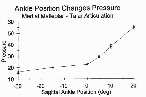
Figure 10.19 Change in force at the medial malleolar-talar articulation as a function of sagittal position of the ankle as measured by force transducers secured to the midpoint of the medial malleolar articular surface. The ankle specimen is axially loaded in neutral and cycled through a sagittal range of motion. (From Michelson JD, Checcone M, Kuhn T, et al. Intra-articular load distribution in the human ankle joint during motion. Foot Ankle Int. 2003;3:226-233, Fig. 5.)


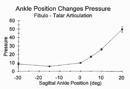
Figure 10.20 Change in force at the lateral malleolar-talar articulation as a function of sagittal position of the ankle as measured by force transducers secured to the midpoint of the lateral malleolar articular surface. The ankle specimen is axially loaded in neutral and then cycled through a sagittal range of motion. (From Michelson JD, Checcone M, Kuhn T, et al. Intra-articular load distribution in the human ankle joint during motion. Foot Ankle Int. 2003;3:226-233, Figure 6.)


Stability of the Ankle Joint

As specified by McCullough and Burge, the stability of the ankle is determined by passive and dynamic factors.18 The passive stability depends on the contour of the articular surfaces, the integrity of the collateral ligaments, the integrity of the distal tibiofibular ligaments, the retinacular system around the ankle, and the crossing and attached tendon tunnels. The dynamic stability is conferred by gravity, muscle action, and the reaction between the foot and the ground.


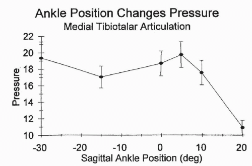
Figure 10.21 Change in force at the medial talar dome tibial plafond articulation as a function of sagittal position of the ankle as measured by force transducers secured to the midpoint of the articular surface of the medial plafond. The ankle specimen is axially loaded in neutral and cycled through a sagittal range of motion. (From Michelson JD, Checcone M, Kuhn T, et al. Intra-articular load distribution in the human ankle joint during motion. Foot Ankle Int. 2003;3:226-233, Fig. 7.)


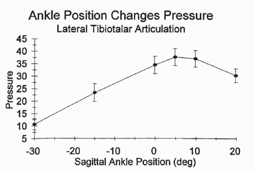
Figure 10.22 Change in force at the talar dome tibial plafond articulation as a function of sagittal position of the ankle as measured by force-transducers secured to the midpoint of the articular surface of the lateral plafond. The ankle specimen is axially loaded in neutral and then is cycled through a sagittal range of motion. (From Michelson JD, Checcone M, Kuhn T, et al. Intra-articular load distribution in the human ankle joint during motion. Foot Ankle Int. 2003;3:226-233, Figure 8.)

The close pack or maximally stable position of the ankle is the dorsiflexed position.30 In the non-weight-bearing position, the side-to-side stability of the ankle is provided mainly by the malleoli and the collateral ligaments, whereas the stability in the sagittal plane is ligament dependent. Posterolaterally and posteromedially, the peronei tendons, the tibialis posterior tendon,
the flexor digitorum longus tendon, the flexor hallucis longus tendon, and their fibrous sheaths contribute to stability.


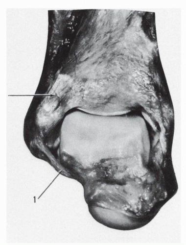
Figure 10.23 In marked plantar flexion the anterior talofibular ligament (1) braces the talus and makes a turn around the anterolateral corner of the talar body.


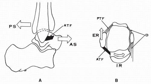
Figure 10.24 Function of the anterior talofibular ligament (ATF). (A) ATF ligament limits the anterior shift of the talus or the posterior shift of the tibia-fibula. (B) ATF ligament limits the internal rotation of the talus or the external rotation of the fibula. (ATF, anterior talofibular ligament; PTF, posterior talofibular ligament; D, deltoid ligament; AS, anterior shift; PS, posterior shift; IR, internal rotation of the talus; ER, external rotation of the fibula.)


Lateral Collateral Ligaments


Stabilizing Function Based on Anatomic Observation

With regard to the lateral collateral ligaments, Inman mentions that as they arise from the fibula close to the axis of ankle joint motion, “the normal flexion and extension movements of the ankle lead to little or no change in tension of these structures.”10 The average location of the axis of motion on the lateral side is 3 mm ± 2 mm distal and 8 mm ± 5 mm anterior to the tip of the lateral malleolus. The anteroinferior location of the axis does introduce appreciable tension in the ligaments unless the axis is specifically, in a given ankle, very close to the tip of the lateral malleolus. Based on dissected anatomic specimens prepared as models, valid observations can be made with regard to their function.

The anterior talofibular ligament is taut in plantar flexion and relaxed in dorsiflexion. It is a major ligament determining the anterior stability in tiptoe standing. In the acutely plantar flexed position, the ligament braces the talus and makes a marked turn around the anterolateral corner of the talar body (Fig. 10.23). It limits the anterior shift and the medial rotation of the talus or the posterior shift of the tibia and the external rotation of the fibula (Fig. 10.24). This ligament also contributes in resisting the lateral talar tilt. According to DeVogel, when the anterior talofibular ligament is formed by two bands, the upper band is taut in plantar flexion but the lower band remains taut in all positions.31


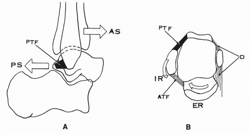
Figure 10.25 Function of the posterior talofibular ligament (PTF). (A) PTF limits the posterior shift of the talus or the anterior shift of the fibula-tibia. (B) PTF limits the external rotation of the talus or the internal rotation of the fibula. (PTF, posterior talofibular ligament; ATF, anterior talofibular ligament; D, deltoid ligament; PS, posterior shift of the talus; AS, anterior shift of the tibia-fibula; ER, external rotation of the talus; IR, internal rotation of the fibula.)

The posterior talofibular ligament has increased tension in dorsiflexion and relaxes in plantar flexion. It braces the talus posteriorly. It limits the dorsiflexion on the foot and the posterior shift of the talus or the anterior displacement of the leg. This ligament is contributory in resisting the external rotation of the talus or the internal rotation of the fibula-tibia. It helps to transmit the internal rotation force of the leg to the talus (Fig. 10.25). Anatomically, the anterior fibers of the ligament are shorter than the posterior fibers. According to DeVogel, the anterior fibers remain taut throughout the entire arc of motion in the sagittal plane, whereas the posterior fibers are tense in dorsiflexion.31

The calcaneofibular ligament is the ligament of the ankle and of the subtalar joint. The tension in the ligament is affected by both joints. This ligament is taut in dorsiflexion and relaxed in plantar flexion (Fig. 10.26). However, in some specimens the
ligament is taut in plantar flexion and less tense in dorsiflexion (Fig. 10.27), whereas in others the tension in this ligament remains constant in all positions.


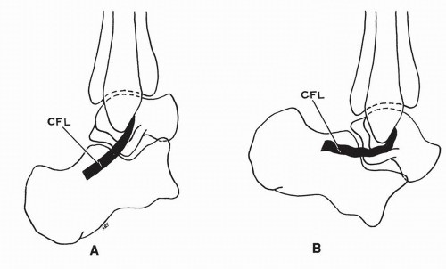
Figure 10.26 Tension in calcaneofibular ligament (CFL). (A) CFL taut in dorsiflexion of ankle. (B) CFL relaxed in plantar flexion of ankle.

The subtalar position affects the tension in the ligament. Here also the results are variable as one observes different specimens. In the specimen of the hindfoot, illustrated in Figures 10.28 10.29, 10.30, with varus position of the os calcis— lateral talar tubercle is high in the sinus tarsi—the calcaneofibular ligament is relatively relaxed. The anterior advancement of the calcaneus contributes to the relaxation of the ligament as its insertion shifts anteriorly. In the same specimen, in the valgus position—lateral talar tubercle low in the sinus tarsi—the os calcis shifts posteriorly relative to the talus and the calcaneofibular ligament is taut.

The variability of the tension in the calcaneofibular ligament may be explained on the basis of the insertional variability of the ligament. As demonstrated by Ruth, the ligament may be oblique, horizontal, vertical, or fan shaped (Fig. 10.31).32 This has a direct bearing on the tension developed by this ligament during motion. When the calcaneofibular ligament is nearly horizontal, in valgus position of the heel, the distance between the origin and the insertion increases; the distance decreases in varus (Fig. 10.32). The ligament is taut in valgus, less tense in varus. When the ligament is vertical in neutral, the distance between the origin and the insertion is increased in varus and decreased in valgus. The ligament is taut in varus and less tense in valgus (see Fig. 10.32). When the ligament has an intermediary obliquity, the ligament tension remains unchanged throughout the motion.


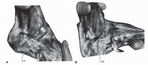
Figure 10.27 In this anatomic specimen of the ankle, the calcaneofibular ligament (CF) is taut in plantar flexion (A) and less tense in dorsiflexion (B).

Inman stressed the coupling effect of the calcaneofibular ligament and the anterior talofibular ligament in preventing the talar tilt on the lateral side.10 In dorsiflexion, the calcaneofibular ligament approaches the vertical position, acts as a true collateral


ligament, of the ankle joint, and prevents the talar tilt of the talus. In plantar flexion, the anterior talofibular ligament is vertical and functions as a collateral ligament, stabilizing the talus laterally. The average angle between the two ligaments, measured in their projection on the sagittal plane, is 105 degrees ± 24 degrees.10 The reciprocal arrangement of the two ligaments is efficient if the angle between the two ligaments is 90 degrees. A horizontal calcaneofibular ligament does not provide the same stability.


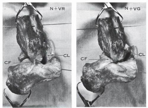
Figure 10.28 Hindfoot specimen, lateral view. The ankle is held in neutral position (N) and the os calcis is moved into varus (VR) or valgus (VG). In varus the calcaneofibular ligament is relaxed and the cervical ligament is vertical and tense. In valgus the calcaneofibular ligament is taut and the cervical ligament is oblique or horizontal but still tense. (CF, calcaneofibular ligament; CL, cervical ligament.)


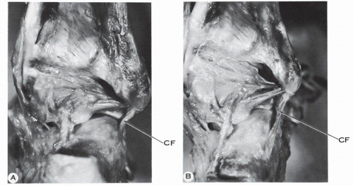
Figure 10.29 Hindfoot specimen, posterolateral view. The ankle is held in neutral. (A) The heel is in varus and the calcaneofibular ligament (CF) is relaxed. (B) The heel is in valgus and the calcaneofibular ligament is taut.


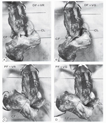
Figure 10.30 Hindfoot specimen, lateral view, in dorsiflexion (DF) and plantar flexion (PF) combined with varus (VR) or valgus (VG) of the os calcis. The dorsiflexion and plantar flexion are indicated by the K-wires implanted in the talus and the os calcis. The valgus and varus are recognized by the relative position of the talus and os calcis: in varus the lateral talar process is away from the posterolateral corner of the sinus tarsi, whereas in valgus the same process strikes or is very close to the sinus tarsi of the os calcis. (A) Combination of dorsiflexion and varus. (B) Combination of dorsiflexion and valgus. The calcaneofibular ligament is taut, more so in valgus. (C) Combination of plantar flexion and varus. (D) Combination of plantar flexion and valgus. In (C) and (D) the calcaneofibular ligament is less taut than in A and B, yet slightly more tension is present in the ligament in valgus. The cervical ligament (CL) is nearly vertical and parallel to the calcaneofibular ligament in dorsiflexion of the ankle and varus of the heel. The cervical ligament is taut in both valgus and varus.


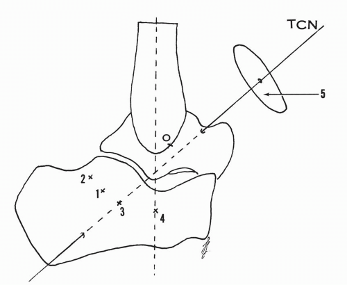
Figure 10.31 Hindfoot, lateral view. O indicates the origin of the calcaneofibular ligament and the numbers 1 to 4 the calcaneal insertion of the same ligament. The variable insertion determines the obliquity of the ligament; 1, common insertion, oblique ligament; 2, horizontal ligament; 3, ligament located along the projection of the talocalcaneonavicular axis (TCN); 4, vertical ligament. The displacement of the insertional points 1 to 4 is along arcs of circles parallel to the circle 5, which is perpendicular to the talocalcaneonavicular axis.

The peroneotalocalcaneal ligament of Rouvière and Canela Lazaro is taut in dorsiflexion and relaxed in plantar flexion. It also limits the anterior displacement of the leg. Both authors have demonstrated that the section of the ligament appreciably increases the anterior displacement of the leg when the foot is stabilized on a table and weight is applied to the anteriorly rotating leg.


Strain Patterns in Lateral Collateral Ligaments

Renstrom and colleagues studied the strain patterns during motion, without load, of the anterior talofibular and calcaneofibular ligaments in five cadaveric ankles.33 The foot was transfixed to a platform at the level of the metatarsal head and the os calcis and the motion of plantar flexion to dorsiflexion was carried out separately or in combination with internal-external rotation of the fixed foot or supination-pronation. In the transfixed foot, the latter motion is truly an inversion-eversion of the foot when both the heel and forefoot are moved forcefully in the same direction. The strain gauges were attached to the mid segment of the corresponding ligament.

In the anterior talofibular ligament, the strain increased 3.3% through the range of motion from 10 degrees of dorsiflexion to 40 degrees of plantar flexion. There was a slight increase in the strain in internal rotation and a decrease in strain of 1.9% in external rotation (Fig. 10.33).


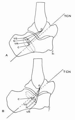
Figure 10.32 Calcaneofibular ligament with common insertion. (A) O indicates the origin of the ligament and N the insertional position in neutral. In valgus (VG) and varus (VR) the displacements occur along the circle C, which is perpendicular to the talocalcaneonavicular axis (TCN). In valgus the distance from the origin to the insertion is longer and the calcaneofibular ligament is taut. In varus the distance is shorter and the ligament is more relaxed. (B) In the vertical type of calcaneofibular ligament, the distance between the origin of the ligament and its insertion is greater in varus and less in valgus. The ligament is taut in varus and relaxed in valgus.

The calcaneofibular ligament remained essentially isometric during the arc of plantar flexion-dorsiflexion at the ankle. The foot position affected the strain pattern in the ligament. External rotation, supination (truly inversion in the present setup), and supination-internal rotation significantly increased the strain in the calcaneofibular ligament relative to the neutral position (Fig. 10.34). The highest values were obtained in dorsiflexion and the strain values greatly diminished with progressive plantar flexion. The synergistic function of the anterior
talofibular ligament and the calcaneofibular ligament was again confirmed. During the arc of extension-flexion, when one ligament is relaxed, the other is strained, and vice versa. This is similar to Inman’s concept of coupling of the two ligaments.


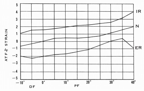
Figure 10.33 Percent strain in anterior talofibular ligament (ATF) with the foot in different degrees of plantar flexion, dorsiflexion—in neutral or combined with external-internal rotation of the foot. In the neutral position of the ankle, the internal rotation increases the strain, whereas the external rotation decreases the strain in the ligament. (Adapted from Renstrom P, Wertz M, Incavo S, et al. Strain in the lateral ligaments of the ankle. Foot Ankle. 1988;9[2]:62.)


Normal Talar Tilt

The instability of the ankle in the coronal plane (lateral talar tilt) and in the sagittal plane (anterior talar shift) is of great clinical significance and has been the subject of extensive investigation in defining the role of the components of the lateral collateral ligament.

Cox and Hewes, in a study of 404 ankles, tested 202 young adults between the ages of 17 and 20 years.32 Manual supination force was applied to the hindfoot with the ankle in approximately 30 degrees of plantar flexion. The measurement was roentgenographic. In this large group, 90.4% had no lateral talar tilt, 7.9% had a tilt between 1 and 5 degrees, and 1.7% had a tilt greater than 5 degrees. One ankle measured 17 degrees, another 16 degrees.


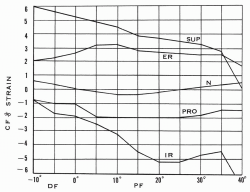
Figure 10.34 Percent strain in calcaneofibular ligament with the foot in different degrees of plantar flexion, dorsiflexion—in neutral or combined with supination-pronation or internal-external rotation of the foot. In neutral position of the ankle, the external rotation or the supination of the foot increases the strain of the ligament, whereas the pronation and the internal rotation decrease the strain. (N, neutral; SUP, supination; PRO, pronation; IR, internal rotation; ER, external rotation.) (Adapted from Renstrom P, Wertz M, Incavo S, et al. Strain in the lateral ligaments of the ankle. Foot Ankle. 1988;9[2]:62.)

Rubin and Witten, in a roentgenographic study of 150 normal volunteers, found the lateral talar tilt to range from 0 to 23 degrees.34 However, 93% of the group had a talar tilt of 10 degrees or less.

Glasgow and coworkers35 consider a talar tilt of up to 6 degrees as normal and, for Freeman,36 a difference in talar tilt of 6 degrees or more between the injured and the uninjured ankle is pathologic. The variations of the normal talar tilt are as indicated in Table 10.3.


TABLE 10.3 VARIATIONS IN DEGREE OF NORMAL TALAR TILT


Author and Method


Normal Talar Tilt


With manual force without anesthesia


Duquennoy and coworkers


5 degrees (0 to 10 degrees)


Cox and Hewes


0 degrees (90.4%)


Glasgow and colleagues up to 6 degrees


>5 to 17 degrees (1.7%)


Freeman


<6 degrees between injured and uninjured


With a device without anesthesia


Rubin and Witten


0 to 23 degrees with 93% ≤ 10 degrees


Sedlin


8 degrees (0 to 15 degrees)


Laurin and St. Jacques


7 degrees (0 to 27 degrees)


Quellet and coworkers


5 degrees (0 to 27 degrees)


Normal Anterior Talar Shift

Normally the talus may be displaced anteriorly when the leg is pressed backward and the heel is brought forward. Landeros and colleagues, in describing the anterior displacement of the talus or anterior drawer sign with manual force, consider the normal anterior talar shift to be 2.5 to 3 mm.37 They also specify that the ankle is to be stressed with the leg-ankle at 90 degrees and “because of the geometry of the bones, anterior displacement of the talus must be accompanied by caudad displacement of the talus as its dome rides forward under the anterior articular margin of the tibia.”37 They further mention that with plantar flexion of 30 degrees or more, the anterior talar shift may not be present; this is probably due to the increased tension in the anterior talofibular ligament. Laurin and Mathieu studied the sagittal mobility of the normal ankle in 40 people ranging in age from 6 to 27 years.38 The force applied on the leg, with the heel being supported on a rest, varied from 20 to 70 lb. The measurements were taken in neutral and equinus. In the neutral position, the anterior talar shift averaged 3.3 to 0.3 mm, and in equinus the average shift was less, measuring 1.3 to 0.2 mm. The methodology used affects the measurements (Table 10.4).


TABLE 10.4 NORMAL ANTERIOR TALAR DISPLACEMENT


Author and Method


Displacement


With manual force


Landeros and colleagues


2.5 to 3 mm


Laurin and Mathieu


In neutral


9.2 mm ± 0.7 mm


In equinus


6.1 mm ± 0.4 mm


With defined force


Laurin and Mathieu


In neutral


3.3 to 0.3 mm


In equinus


1.3 to 0.2 mm


Castaing and Delaplace


5 to 8 mm


Experimental Studies of Anterior and Lateral Ankle Stability and Transverse Rotational Stability

The contribution of the components of the lateral collateral ligaments to the stability of the ankle in the frontal, sagittal, and transverse planes has been analyzed in experimental setups. The ligamentous components are transected in a sequential manner, the ankle is subjected to stress, and the displacement of the talus is assessed.

Glasgow and colleagues examined 20 cadaveric ankles.39 Division of the anterior talofibular ligament allowed anterior subluxation and medial rotation of the talus. There was no lateral talar tilt with the varus stress except for a minimal degree at the extreme of plantar flexion. The transection of both the anterior talofibular and the calcaneofibular ligaments resulted in marked lateral tilt and anteromedial subluxation of the talus when the foot was plantigrade or in equinus. The isolated division of the calcaneofibular ligament resulted in a minor degree of lateral talar tilt when the foot was plantigrade and the anterior talar subluxation was absent (Fig. 10.35).

Johnson and Markolf analyzed the supportive role of the anterior talofibular ligament in a quantitative manner.40 Thirty fresh-frozen cadaver ankles were used in their investigation. Initially the intact specimens were subjected to an increasing anteroposterior force of a maximum of ± 100 N and an inversioneversion or internal-external torque of a maximum of ± 2 N · m applied on the talus. The displacements of the talus were measured in the three orthogonal planes and the same measurements were repeated after transection of the anterior talofibular ligament. After sectioning the anterior talofibular ligament, the anterior talar shift increased 93%, or 4.3 mm ± 2 mm, from 5.5 mm ± 1.7 mm in the dorsiflexed position (Fig. 10.36). In neutral position, the anterior shift increased 64%, or 3.7 mm ± 1.88 mm, from 6.6 mm ± 2.3 mm, and 39%, or 2.5 mm ± 1.6 mm, from 5.8 mm ± 1.8 mm in plantar flexion. With an inversion torque of 2 N · m, the lateral talar tilt increased 49%, or 5.2 degrees ± 2.3 degrees, from 12.6 degrees ± 3.8 degrees plantar flexion (Fig. 10.37). In the neutral ankle position, the initial lateral talar tilt of 9.6 degrees ± 3.2 degrees increased 2.8 degrees ±1.9 degrees, or 35%, after transection of the ligament, and in dorsiflexion the initial tilt of 7.2 degrees ±2.5 degrees increased 2.5 degrees ±1.5 degrees, or 43%.

These findings demonstrated the occurrence of lateral talar tilt with the transection of the anterior talofibular ligament in all positions of the ankle, in contradiction to the previous studies indicating a lateral talar tilt only in extreme plantar flexion. These results “establish the structural importance of the anterior talo-fibular ligament in all positions of flexion for three modes of loading.”40

With an internal rotational torque of 2 N · m, the internal rotation of the talus of 14.3 degrees ± 5.1 degrees increased 10.8 degrees ± 6.1 degrees, or 86%, in plantar flexion (Fig. 10.38). In the neutral position, the initial internal rotation of 13.8 degrees ± 4.6 degrees increased 7.7 degrees ± 4.6 degrees, or 62%, after
transection of the ligament, and in dorsiflexion the increase was 5.7 degrees ±3.6 degrees, or 62%, from the initial talar rotation of 10.2 degrees ±6.7 degrees. In essence, the release of the anterior talofibular ligament increases the anteromedial shift of the talus and allows a lateral talar tilt.

McCullough and Burge analyzed the rotary stability of the load-bearing talus.18 In eight intact cadaveric ankles held in plantigrade position, a horizontal torque of 3 N · m was applied to the talus. Weight bearing was simulated by applying vertical loads ranging from 1 to 50 kg and the horizontal rotation of the talus was assessed. With the ligaments intact, under a load of 1 kg, the horizontal rotation of the talus was 24.1 degrees and decreased 7.5 degrees ±1.5 degrees in a linear fashion as the vertical load reached 50 kg (see Fig. 10.13). In three ankles with the division of the anterior talofibular ligament, the range of medial talar rotation at a load of 15 kg increased by 5.9 degrees ±1.9 degrees, but the joint was stable to inversion stress. The progressive transection of the calcaneofibular and the posterior talofibular ligaments increased the medial talar rotation another 5.4 degrees ±1.9 degrees. There was, however, a substantial decrease in the horizontal talar rotation under a vertical load of 50 kg (Fig. 10.39).


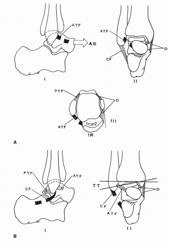
Figure 10.35 (A) The isolated tear of the anterior talofibular ligaments results in (I) anterior shift of the talus, (II) no lateral tilt of the talus with varus stress except for a minimal degree at the extreme of plantar flexion, (III) medial rotation of the talus. (B) The isolated transection of the calcaneofibular ligament results in (I) no anterior shift, (II) minor lateral talar tilt when the foot is plantar flexed.


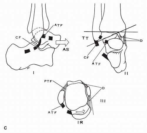
Figure 10.35 (Continued) (C) Transection of the anterior talofibular and calcaneofibular ligaments results in (I) marked anterior shift of the talus, (II) lateral talar tilt, (III) internal rotation of the talus when the foot is plantar flexed. (ATF, anterior talofibular ligament; CF, calcaneofibular ligament; PTF, posterior talofibular ligament; IR, internal rotation of talus.) (Data from Glasgow M, Jackson A, Jamieson AM. Instability of the ankle after injury to the lateral ligament. J Bone Joint Surg Br. 1980;62[2]:196.)


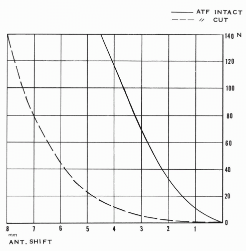
Figure 10.36 Anterior shift of the talus before and after section of the anterior talofibular ligament in dorsiflexion with variable degree of force applied. (ATF, anterior talofibular ligament; ANT shift, anterior displacement; N, Newton [force unit applied].) (Curve adapted from Johnson EE, Markolf KL. The contribution of the anterior talo-fibular ligament to ankle laxity. J Bone Joint Surg Am. 1983;65[1]:86.)


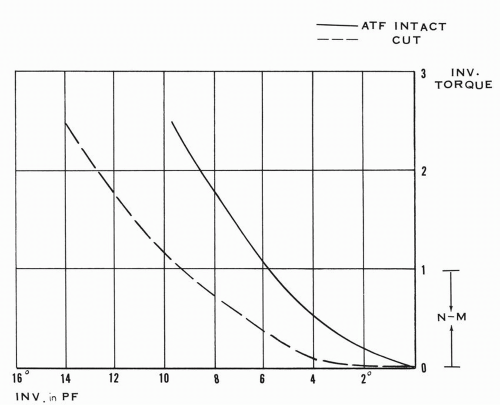
Figure 10.37 Inversion of the talus or lateral talar tilt in plantar flexion before and after section of the anterior talofibular ligament with variable inversion torque applied. (ATF, anterior talofibular ligament; INV, in PF, inversion or lateral tilt in plantar flexion; INV torque, inversion torque in N-M [Newtonmeters].) (Curve adapted from Johnson EE, Markolf KL. The contribution of the anterior talo-fibular ligament to ankle laxity. J Bone Joint Surg Am. 1983;65[1]:86.)


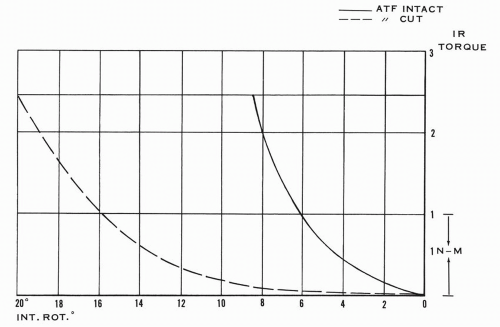
Figure 10.38 Internal rotation of the talus before and after section of the anterior talofibular ligament with variable internal rotation torque applied. (ATF, anterior talofibular ligament; INT. RCT., internal rotation of talus; IR TORQUE, internal rotational torque in N-M [Newton-meters].) (Curve adapted from Johnson EE, Markolf KL. The contribution of the anterior talo-fibular ligament to ankle laxity. J Bone Joint Surg Am. 1983;65[1]:86.)


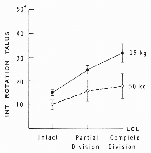
Figure 10.39 Mean range of medial talar rotation under vertical loading with lateral collateral ligament (LCL) intact, with partial division (section of the anterior talofibular ligament), and with complete division of the ligament (added section of the calcaneofibular and posterior talofibular ligaments). (McCullough CJ, Burge PD. Rotary stability of the load-bearing ankle. An experimental study. J Bone Joint Surg Br. 1980;62[4]:461.)

To simulate an external rotational injury of the ankle, a sequential division of the anterior two thirds of the deltoid ligament, the anterior tibiofibular ligament, and the posterior talofibular ligaments was carried out and the stressed external rotation of the talus was measured. With a vertical load of 15 kg there was a linear progressive increase of 20 degrees in the talar rotation from 24 to 46 degrees, or 83%. With vertical loading of 50 kg, the rotation decreased to 30 degrees (Fig. 10.40).


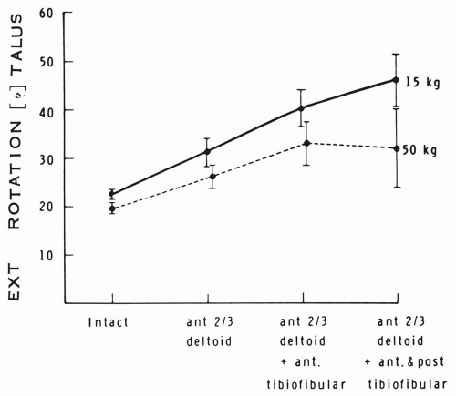
Figure 10.40 Mean range of external talar rotation under vertical loading with the ligaments intact and with sequential cuts of the anterior two thirds of the deltoid ligament and the anterior and posterior tibiofibular ligaments. (McCullough CJ, Burge PD. Rotary stability of the load-bearing ankle. An experimental study. J Bone Joint Surg Br. 1980;62[4]:461.)

In five ankles, the isolated transfixation of the inferior tibiofibular syndesmosis decreased the external talar rotation by 9.3 degrees ±1.3 degrees at 15 kg and by a smaller amount at 50 kg (Fig. 10.41). McCullough and Burge also presented the interesting concept of the components of the collateral ligaments forming a ring resisting the horizontal rotation (external or internal) of the talus by tension in opposing pairs (Fig. 10.42).18 They also specified that the range of horizontal rotation measured in their cadaveric ankles is greater than that in living subjects, because of the added dynamic stability provided by the muscles.

Rasmussen conducted a comprehensive study of the stability of the ankle in function of the supportive ligaments.41 This anatomic pool consisted of 152 cadaveric ankles, mostly elderly. In a subgroup of 113 ankles, mobility pattern curves were determined with a pin inserted into the talus connected to torque and angle sensors registering the rotary movements in the ankle simultaneously in two planes when affecting the talus by a torque of 1.5 N · m in different directions. The study was conducted with intact and with divided ligaments.

With intact ligaments, in 113 ankles, the dorsiflexion-plantar flexion was about 58 degrees, with dorsiflexion 20.87 degrees ± 7.53 degrees and plantar flexion 36.89 degrees ± 8.97 degrees. In 50 ankles, the talar tilt or talar adduction was 5.58 degrees ± 2.68 degrees, and the reverse talar tilt or talar abduction measured 4.84 degrees ± 1.96 degrees. Internal rotation of the talus in 63 ankles was 8.60 degrees ±2.62 degrees, and the external rotation was 8.21 degrees ±3.02 degrees.


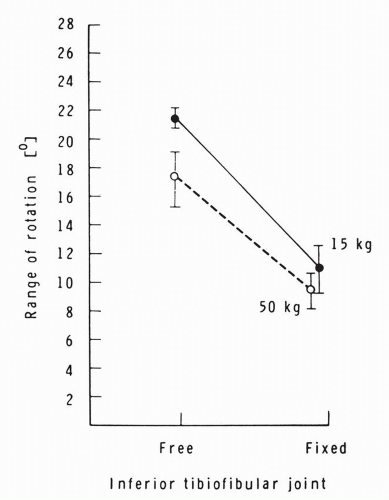
Figure 10.41 Mean range of talar external rotation under vertical load with the inferior tibiofibular joint free or fixed. (McCullough CJ, Burge PD. Rotary stability of the load-bearing ankle. An experimental study. J Bone Joint Surg Br. 1980;62[4]:402.)

The mobility pattern was analyzed in 12 ankles in the frontal plane and another 12 ankles in the horizontal plane after transection of the anterior talofibular ligament. In the frontal plane the talar tilt or adduction increased 4.83 degrees ± 1.80 degrees, mainly in plantar flexion. In the horizontal plane the medial rotation of the talus increased 10 degrees ±3.59 degrees (Figs. 10.43 and 10.44).

With transection of both the anterior talofibular ligament and the calcaneofibular ligament in nine ankles, the talar tilt or adduction increased 11.44 degrees ± 6.15 degrees, mostly in dorsiflexion and neutral. The medial rotation of the talus increased and the external rotation was unaffected also (see Figs. 10.43 and 10.44). Transection of the anterior talofibular ligament, the calcaneofibular ligament, and the entire posterior talofibular ligament resulted in marked instability. The lateral talar tilt was 45 to 60 degrees, the horizontal talar medial rotation increased to more than 21 degrees, and the talar external rotation increased by 10.67 degrees ± 4.63 degrees (see Figs. 10.43 and 10.44). The isolated transection of the calcaneofibular ligament in six ankles produced a negligible increase of 1.33 degrees ± 1.37 degrees in the lateral talar tilt, and the medial or lateral talar horizontal rotation was nearly unaffected.


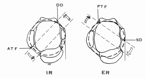
Figure 10.42 The components of the collateral ligaments of the ankle forming a ring resisting the horizontal rotation of the talus by tension in opposing pairs. Resisting the internal rotation (IR): the anterior talofibular ligament and the deep deltoid ligament. Resisting the external rotation (ER): the posterior talofibular ligament and the superficial deltoid ligament. (ATF, anterior talofibular ligament; DD, deep deltoid ligament; PTF, posterior talofibular ligament; SD, superficial deltoid ligament.)

Cass and coworkers investigated, in non-axially loaded configuration, the stability role of the components of the lateral collateral ligament in seven cadaveric ankles subjected to an inversion force.42 The study was performed with intact ligaments and with serial transections of the same. The calcaneus remained transfixed to its reference grid. Quantitative triaxial measurements of the motion were made. In the intact specimens with an inversion force of 2 kg, there was 12.1 degrees of adduction and 3.6 degrees of external rotation of the tibia relative to the talus. The tibial motion relative to the calcaneus was a mean maximum of 38 degrees of adduction and 24 degrees of external rotation. The sequential division of the three components of the lateral collateral ligament in an anteroposterior direction produced a gradual increase of the tibial adduction-external rotation. The isolated division of the calcaneofibular ligaments minimally affected these motions, with a 10% increase in adduction and a 3% increase in external rotation near 15 degrees of plantar flexion, whereas that of the anterior talofibular ligament increased the tibial adduction by 30% and the external rotation by 8% at 30 degrees of plantar flexion.

The combined division of these two ligaments produced instability near neutral position, with a tibial adduction increase of 41% and an external rotation increase of 65 degrees (Fig. 10.45). Cass and colleagues stressed the importance of the coupling of the adduction-external rotation instability of the leg and attributed the sensation of “giving ‘way’” in the patients with unstable ankles during gait “to a sudden external rotation subluxation of the leg on the talus.”42 The normal mandatory external rotation of the leg with respect to the fixed foot when walking on level ground occurs at 15% to 20% of the stance phase and the external rotation of the tibia-fibula relative to the

talus is resisted by the anterior talofibular ligament.42 This ligament is an essential component of the supportive horizontal ligamentous ring (see Fig. 10.42). The external rotation of the leg places the ligament under tension and the excess may lead to its rupture.


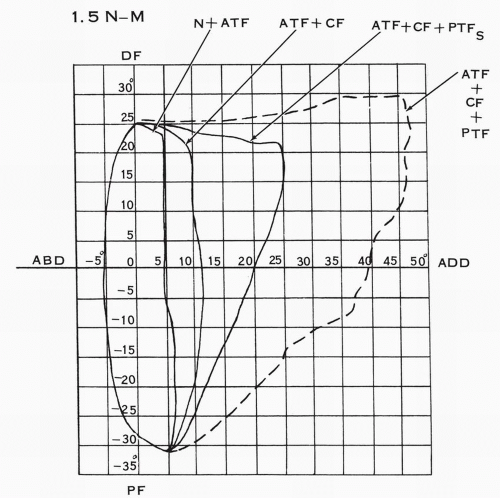
Figure 10.43 Mobility pattern in the sagittal and front planes after progressive section of the components of the lateral collateral ligament. The torque applied is 1.5 N-m. (N, neutral; ATF, anterior talofibular ligament; CF, calcaneofibular ligament; PTFS, posterior talofibular ligament short fibers; PTF, total posterior talofibular ligament; DF, dorsiflexion; PF, plantar flexion; ABD, abduction of talus; ADD, adduction of talus or lateral talar tilt.) (Adapted from Rasmussen O. Stability of the ankle joint. Analysis of the function and traumatology of the ankle ligaments. Acta Orthop Scand. 1985;56[Suppl 211]:34.)


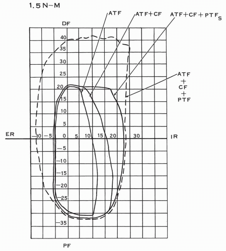
Figure 10.44 Mobility pattern in the sagittal and horizontal planes after progressive section of the components of the lateral collateral ligaments. The torque applied is 1.5 N-m. (ATF, anterior talofibular ligament; CF, calcaneofibular ligament; PTFS, short fibers of posterior talofibular ligament; ER, external rotation; IR, internal rotation; DF, dorsiflexion; PF, plantar flexion.) (Adapted from Rasmussen O. Stability of the ankle joint. Analysis of the function and traumatology of the ankle ligaments. Acta Orthop Scand. 1985;56[Suppl 211]:34.)


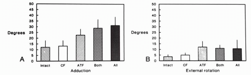
Figure 10.45 Mean maxima for adduction (A) and external rotation (B) of the tibia relative to the talus with the lateral collateral ligament intact and with sequential transection of its components. (G; calcaneofibular ligament; ATF, anterior talofibular ligament.) (Cass JR, Morrey BF, Chao EYS. Three-dimensional kinematics of ankle instability following serial sectioning of lateral collateral ligaments. Foot Ankle. 1984;5[3]:45.)


Experimental Study of Posterior Ankle Stability

Harper investigated posterior ankle stability in six cadaveric ankles.43 The posterior malleolus was ostectomized and the ankle was subjected to a posteriorly directed stress force, and the stability was assessed by lateral radiographs. The removed posterior malleolar fragment was increasingly larger, representing 30% to 40% and then 50% of the tibial articulating surface. No posterior talar subluxation was observed. In all six specimens, the medial malleolus was then ostectomized and the same posteriorly directed force applied manually, and no talar posterior shift was observed. By indirect proof, Harper concluded that the posterior talofibular ligament and the calcaneofibular ligaments “appeared to be the key structures providing posterior talar stability.”


Mechanical Characteristics of the Lateral Collateral Ligaments

The tensile strength of the anterior talofibular ligament was investigated by St. Pierre and colleagues in 36 cadaver ankles.44 The specimens consisted of the ligament attached to the lateral malleolus and to the talus. The average age of the cadavers was 64 years, with a range of 27 to 86 years. The tensile tests were conducted in pure tension to rupture or avulsion with the long axis of the anterior talofibular ligament nearly parallel to the axis of the lateral malleolus; the displacement rate was 12.5 cm/min. The tensile strength of the ligament to rupture had a mean value of 206 N (21 kg), ranging from 58 to 556 N (5.9 to 56.7 kg). In 50%, the failure was by bony avulsion from the talus and in 45% it was by mid substance failure. In 5%, the mode of failure was not clear, but none avulsed from the fibula.

Attarian and colleagues conducted a biomechanical study of the lateral collateral ligament and compared segments of tendon (peroneus brevis, split peroneus brevis, long extensor of the fourth toe).45 Twenty cadaveric ankles provided the bone-ligament-bone specimen of the anterior talofibular and the calcaneofibular ligaments. The donor age ranged from 23 to 82 years, with a mean of 58 years. Load-deflection tests were conducted to the point of failure. Cyclic loading at physiologic deflections prior to testing was done to stabilize the specimens. The anterior talofibular ligament load to failure was 138.9 N ± 23.5 N, and that of the calcaneofibular ligament was 345.7 N ± 55.2 N. Comparatively, the tensile strength to rupture of the peroneus brevis tendon and of the split peroneus brevis tendon was nearly the same, 258.1 N ± 63.5 N and 258.8 N ± 110.6 N, respectively. The long extensor of the fourth toe ruptured at 130.1 N ± 20.9 N.

Siegler and coworkers studied the tensile mechanical properties of the collateral ligaments of 20 ankles.46 The average donor age was 67.8 ± 15.2 years, ranging from 33 to 85 years. The lateral collateral ligaments were prepared as bone-ligamentbone. In each experiment, the long axis of the tested ligament was aligned with the line of application of the tensile force. The specimen was initially subjected to 15 preconditioning cycles. The maximal tensile force was increased by 44.5 N until failure of the ligament by avulsion or rupture. Tension-ligament elongation curves were determined (Fig. 10.46) where the yield point-load represents the failure of some fibers of the ligament that is still intact and the ultimate load corresponds to the failure of the ligament.

The anterior talofibular ligament had a yield force of 222 N and an ultimate load of 231 N and elongated 0.246 cm on average. The failure occurred by bone avulsion in 58% and by rupture in 42%. The calcaneofibular ligament yield force was 289 N and failure occurred at an ultimate load of 307 N. The mode of failure was bone avulsion in 70% and substance rupture in 30%. The strongest of the lateral collateral ligaments was the posterior talofibular ligament, with a yield force of 400 N and an ultimate load of 418 N, and a mode of failure similar
to that of the calcaneofibular ligament. These experiments were conducted with the tested ligament oriented near vertically, which corresponds to a position of plantar flexion for the anterior talofibular ligament and a position of dorsiflexion for the calcaneofibular and the posterior talofibular ligaments.


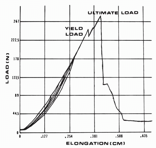
Figure 10.46 Tension-elongation results obtained from a tensile test conducted on a lateral collateral ankle ligament prepared as bone-ligament-bone. The yield point-load represents the failure of some fibers of the ligament, which is still intact. The ultimate load corresponds to the failure of the ligament. (N, Newton.) (Siegler S, Block J, Schneck CD. The mechanical characteristics of the collateral ligaments of the human ankle joint. Foot Ankle. 1988;3[5]:239.)


Deltoid Ligament


Anatomic Observations

Contrary to the lateral collateral ligament, the deltoid ligament is one ligament, in continuity, with some overlapping of its constitutional fibers. A division of this ligament into distinct anatomic separate entities is artificial and can be accomplished only by considering their insertional sites.

The ligament may be considered as being formed by two layers: superficial and deep. The superficial layer, delta shaped, extends from the anterior colliculus to insert on the talus, the navicular, the inferior calcaneonavicular ligament, the sustentaculum tali, and the posteromedial talar tubercle. The deep layer extends from the intercollicular groove and the inferior colliculus to the talar body as one or two strong bands.

The deep deltoid, the strongest component, prevents the lateral shift of the talus and limits the dorsiflexion of the ankle or the anterior rotation of the leg when the foot is stabilized. Its fibers are nearly horizontal in orientation and resist the external rotation of the leg relative to the talus or the internal rotation of the talus. It is an important component of the peritalar horizontal ligamentous ring (see Fig. 10.42). The talocalcaneal component of the superficial deltoid ligament limits the eversion of the calcaneus at the subtalar joint and contributes to the medial stability of the talus. The anterior tibiotalar ligament and the tibionavicular ligament restrict the plantar flexion of the foot and ankle. The former limits the external rotation of the talus in the ankle mortise and contributes to the transmission of the internal rotation of the tibia to the talus. The tibio-spring ligament fascicle or the superficial deltoid ligament provides the suspensory support to the inferior calcaneonavicular ligament against gravity and against the dynamic pressure exerted inferomedially by the talar head. The plantar segment of the tibialis posterior tendon supplements this support.


Experimental Investigation of the Role of the Deltoid Ligament

Close, in his experimental investigation, demonstrated the importance of the deep deltoid ligament in limiting the lateral talar shift (Fig. 10.47).16 Harper defined the relative functional role of the superficial and deep components of the deltoid ligament and of the lateral malleolus in a study of 24 cadaveric ankles subjected to manual stressing.47 The talar anterior and lateral shifts and the medial or valgus tilt were assessed. In the ankles, with transection of the anterior capsule, there was no talar lateral shift or medial tilt with stress. The anterior talar shift was limited to an average of 0.9 mm (range, 0 to 2.5 mm). With the lateral malleolus and its ligaments intact, transection
of the superficial or the deep deltoid component resulted in no change in the talar lateral or anterior shift or in the medial tilt. The transection of both the superficial and deltoid ligaments resulted in a medial talar tilt or abduction of 14 degrees (range, 13 to 16 degrees) but without associated increase of the talar anterior or lateral shift (Fig. 10.48).


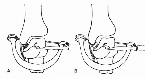
Figure 10.47 Lateral displacement of the talus after excision of the fibula and after added transection of the deep component of the deltoid ligament. (A) Talus laterally displaced 2.0 mm after removing fibula. (B) After sectioning the deep portion of the deltoid ligament 3.7 mm displacement of talus is possible. (Close JR. Some applications of the functional anatomy of the ankle joint. J Bone Joint Surg Am. 1956;38[1]:766.)

With removal of the lateral malleolus and both components of the deltoid ligament intact, there was no talar medial tilt or abduction. However, the anterior talar shift increased an average of 5.6 mm (range, 4 to 6 mm), and the lateral talar shift increased an average of 1.9 mm (range, 1.5 to 3 mm).

The transection of the superficial deltoid did not then affect the talar stability.


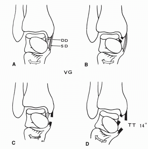
Figure 10.48 Medial talar tilt or talar abduction with valgus stress applied. (A) Superficial and deep deltoid components intact. (B) Transection of deep deltoid: no talar tilt. (C) Transection of superficial deltoid: no talar tilt. (D) Transection of both deltoid components: medial talar tilt. The lateral malleolus is intact. (SD, superficial deltoid ligament; DD, deep deltoid ligament; TT, medial talar tilt; VG, valgus stress.) (Data from Harper MC. Deltoid ligament: An anatomical evaluation of function. Foot Ankle. 1987;8[1]:19.)

With the superficial deltoid remaining intact, the transection of the deep deltoid ligament would result in an increase in the anterior talar shift to 8 mm (range, 7 to 9 mm) and in the lateral talar shift to 3.8 mm (range, 3 to 4.5 mm) (Fig. 10.49). No medial or valgus tilting of the talus was possible. Harper concluded the following:


An anterior talar shift of 2.5 mm is possible in an ankle intact except for the anterior capsule.

The deltoid ligament is the primary restraint against the talar valgus tilt.

The lateral malleolus and its ligament are the primary restraints against the anterior and lateral talar shifts. The deep deltoid ligament is the secondary restraint against the lateral and anterior talar shifts.


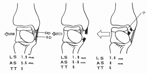
Figure 10.49 The lateral malleolus is excised. The talar lateral shift (LS), anterior shift (AS), and medial tilt (TT) are assessed with the components of the deltoid intact or with the transection of the superficial or the deep components of the deltoid ligament. The displacements are indicated in average millimeter values. (Data from Harper MC. Deltoid ligament: An anatomical evaluation of function. Foot Ankle. 1987;8[1]:19.)

Rasmussen investigated the contribution of the different components of the deltoid ligament by transection and experimental determination of the mobility pattern of the ankle.41 For the sake of clarifying the findings, the anatomic interpretation used by Rasmussen is to be defined first.

The tibiocalcaneal ligament is considered the sole component of the superficial deltoid ligament. The anterior tibiotalar ligament is considered “the anterior portion of the deep layer of the deltoid ligament.” The intermediate tibiotalar ligament and the posterior tibiotalar ligament are also components of the deep deltoid.

In our interpretation, although the last two are indeed deep components of the ligament, the anterior tibiotalar and tibionavicular ligaments are considered as superficial components. Furthermore, the tibio-spring ligament component, a superficial component of the deltoid ligament, has not been recognized in this investigation.

In 15 ankles, the transection of the tibiocalcaneal ligament increased the abduction of the talus or the medial tilt by 2.27 degrees ± 1.83 degrees. The talar mobility in the horizontal or the sagittal planes was not altered. In seven ankles, cutting of the tibiocalcaneal ligament and the anterior tibiotalar ligament minimally altered the above instability and plantar flexion did not increase. In four ankles, transection of the tibiocalcaneal ligament, the anterior talotibial ligament, and the intermediate talotibial ligament, which in our interpretation is equivalent to transection of most of the superficial deltoid ligament and of the anterior component of the deep deltoid ligament, resulted in an increase of 8.75 degrees ± 4.19 degrees in talar abduction, most marked in plantar flexion. In the horizontal plane, the abnormal lateral rotation of the talus amounted to 2.40 degrees ± 1.52 degrees. In addition to the above components, transection of the posterior tibiotalar ligament or the major component of the deep deltoid ligament resulted in such a lax ankle medially that no mobility pattern could be plotted. Isolated cutting of the anterior tibiotalar ligament did not cause any instability.

Quiles and coworkers investigated the function of the components of the deltoid ligament in 35 ankles by measuring the distance between the origin and the insertion of the ligaments at rest, during flexion-extension at the ankle, and during abductionpronation of the foot.48 Pins were inserted at the attachment sites of the ligaments and the distances measured and plotted.

In plantar flexion, the calcaneotibial ligament and the posterior talotibial ligament relax, and the tibionavicular ligament is taut. In dorsiflexion, the reverse occurs. With abduction of the foot, the tibionavicular ligament is under tension and the posterior tibiotalar ligament is relaxed.

The transection of the posterior tibiotalar ligament affects the function of the other components, but the reverse does not occur. With complete transection of the deltoid, there was lateral displacement of the talus.


Mechanical Characteristics of the Deltoid Ligament

Siegler and colleagues investigated the tensile mechanical properties of the components of the deltoid ligament with the same anatomic pool of 20 ankles used to study the lateral collateral ligament.46 Surprisingly, their investigation indicated an early failure of the tibiocalcaneal ligament at an ultimate load of 44.5 N, indicating a negligible support provided by this component. In their study “it was discarded as a significant supporting structure of the ankle.”

In reviewing the anatomic preparation of the different components of the deltoid ligament (specifically in Figures 1 and 2 in the article by Siegler and colleagues46) it appears to us that the tibiocalcaneal ligament has been “prepared” as an unusually narrow band, which is not the case in our anatomic dissections. This may account for the weak mechanical characteristics reported in this study.

The posterior tibiotalar ligament or major component of the deep deltoid ligament had superior mechanical properties with a yielding force of 405 N and an ultimate load of 467 N.

The mode of failure was avulsion in 60% and tear in 40%. This ligament thus could provide significant resistance to ankle dorsiflexion and to lateral or posterior shift of the talus. The tibio-spring ligament also manifested strong mechanical characteristics, with a yield force of 351 N and an ultimate load of 432 N. The mode of failure was avulsion in 31% and tear in 69%. Our interpretation of the potential function of this ligament has already been presented in the functional study of the deltoid ligament. The superficial tibionavicular ligament was the weakest, with a yield force of 107 N and an ultimate load of 120 N. The mode of failure was tearing in 100%.


Stability of the Loaded Ankle

Stormont and coworkers studied the stability of the loaded ankle in 12 distal leg-midfoot specimens that were stabilized through the tibia and the calcaneus.49 The specimen was equilibrated with the foot at 90 degrees to the long axis of the tibia and tested with an axial load of 0 N and 670 N (68 kg). Six specimens were subjected to internal and external rotational stress in unloaded and loaded conditions. The stability of the ankle with intact or divided ligament(s) was studied in 20 degrees of plantar flexion, in neutral, and in 15 degrees of dorsiflexion in two specimens each. The six remaining specimens were tested identically with inversion-eversion loads. The serial sectioning was performed in a sequential manner: posterior talofibular, calcaneofibular ligament, retinaculum, anterior joint capsule, anterior talofibular ligament, posterior capsule, deltoid ligament, lateral talocalcaneal ligament, and finally the tibiofibular syndesmosis. A torque ranging from 336 to 398 Nm was applied to determine the initial range of displacement.


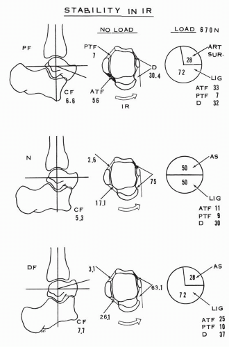
Figure 10.50 Stability of the ankle in internal rotation stress with and without vertical load of 670 N (newtons). Percentage of restraint to the internal rotation torque-displacement by each component of the collateral ligaments and the articular surfaces is presented in neutral, dorsiflexion, and plantar flexion positions of the ankle. (ATF, anterior talofibular ligament; PTF, posterior talofibular ligament; CF, calcaneofibular ligament; D, deltoid ligament; AS, articular surface; IR, internal rotation.) (Data from Stormont DM, Morrey BF, Kai-nan AN, et al. Stability of the loaded ankle. Relation between articular restraint and primary and secondary static restraints. Am J Sports Med. 1985;13[5]:295.)

Stormont and colleagues, by arbitrary convention, considered any structure providing more than 33% of the restraint to a specific displacement as a primary restraint, whereas a structure providing 10% to 33% of the restraint was considered a secondary restraint, and a structure providing less than 10% was considered an insignificant contributor to the stability of the joint.49 In internal rotation of the foot on the leg with 20 degrees of plantar flexion and without load, the anterior talofibular ligament provided 56% of resistance and the deltoid 30%; they are considered the two primary major restraints. Their restraining function was determined by the ankle position. In neutral, the deltoid provided 75% of the stability and the anterior talofibular ligament 17%; in dorsiflexion, the deltoid contributed 63% of the restraint and the anterior talofibular ligament 26%. The calcaneofibular ligament and the posterior talofibular ligaments were insignificant contributors (Fig. 10.50).

Under load, in neutral position, the articular surface provided 50% of the stability and the posterior talofibular ligament became a secondary constraint. In external rotation of
the foot on the leg without load, the calcaneofibular ligament becomes a major contributor, averaging 65% to stability. The posterior talofibular ligament is a secondary restraint. This ligament provides no resistance in 15 degrees of dorsiflexion. The deltoid ligament and the anterior talofibular ligament have secondary influences. With loading, the calcaneofibular restraint averages 43% and the posterior talofibular ligament 24%. The deltoid ligament now provides substantial support, averaging 20% except in neutral (3.2%), and the anterior talofibular ligament contributes an average of 17% to stability except in plantar flexion (5.3%). The articular surfaces under loading provide an average of 27% of stability (Fig. 10.51).

In inversion or varus stress, the lateral collateral ligament provided 87% of the resistance in the unloaded condition with the following average contribution from each component: anterior talofibular ligament, 27%; calcaneofibular ligament, 53%; posterior talofibular ligament, 11%, with only 5.6% contribution in plantar flexion. The deltoid ligament provided insignificant resistance in neutral and dorsiflexion and 11% in plantar flexion. In the loaded condition, no ligament contributed to stability, and the restraint was provided 100% by the articular surfaces. In eversion or valgus stress, the deltoid ligament provided 83% of the stability and the lateral collateral ligament 17% (Fig. 10.52). In the loaded mode, once again no ligament contributed to stability, and the resistance to the valgus stress was 100% articular. The study indicates that during inversion or eversion, “the ankle instability may occur during loading or unloading but not once the ankle is fully loaded.”49


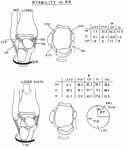
Figure 10.51 Stability of the ankle in external rotation stress with and without vertical load of 670 N (newtons). Percentage of restraint to the external rotation torquedisplacement by each component of the collateral ligaments and the articular surfaces is presented in neutral, dorsiflexed, and plantar flexed positions of the ankle. The calcaneofibular ligament is a major restraining structure. (ATF, anterior talofibular ligament; PTF, posterior talofibular ligament; CF, calcaneofibular ligament; D, deltoid ligament; AS, articular surface; AV, average contribution; ER, external rotation.) (Data from Stormont DM, Morrey BF, Kai-nan AN, et al. Stability of the loaded ankle. Relation between articular restraint and primary and secondary static restraints. Am J Sports Med. 1985;13[5]:295.)


FUNCTIONAL SEGMENTAL ANALYTIC STUDY OF THE FOOT


Subtalar or Talocalcaneal Joint Motion


Single Axis of Motion

The axis of the subtalar joint was studied by Manter,50 Hicks,12 Isman and Inman,51 and Inman.10 It is oblique,
oriented upward, anteriorly and medially. It penetrates the posterolateral corner of the os calcis, passes perpendicular to the canalis tarsi, and pierces the superomedial aspect of the talar neck. Manter reported the angulation of the axis to have a 42 degrees average inclination (range, 29 to 47 degrees) in the sagittal plane relative to the horizontal line and a 16 degrees average medial deviation (range, 8 to 24 degrees) in the transverse plane relative to the long axis of the foot passing through the first interdigital space.50 Inman provided measurements that are very similar: 42 degrees ± 9 degrees of inclination in the sagittal plane and 23 degrees ± 11 degrees of medial deviation in the horizontal plane relative to the axis of the foot passing through the second interdigital space (Fig. 10.53).10


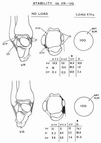
Figure 10.52 Stability of the ankle in varus and valgus stress with and without vertical load of 670 N. Percentage of restraint to the varus or valgus stress by each component of the collateral ligaments and the articular surfaces is presented in neutral, dorsiflexion, and plantar flexion of the ankle. The calcaneofibular ligament is a major restraining structure in varus stress, whereas the deltoid ligament is a major restraining structure in valgus stress of the ankle. Under vertical load the stability is provided by only the articular surfaces. (Data from Stormont DM, Morrey BF, Kai-nan AN, et al. Stability of the loaded ankle. Relation between articular restraint and primary and secondary static restraints. Am J Sports Med. 1985;13[5]:295.)

The motion components at the subtalar joint can be determined from a simple vectorial analysis of the subtalar joint axis components, which are three: longitudinal, vertical, transverse. The greater longitudinal component generates supination-pronation, the vertical component generates abductionadduction, and the lesser transverse component generates flexion-extension. Any instantaneous motion is a combination of the three simultaneously occurring motions. The axis of the talocalcaneal joint invariably generates two combination patterns of motion: pronation-abduction-extension and supination-adduction-flexion (Figs. 10.54, 10.55, and 10.56). This basic motion of the calcaneus was clearly demonstrated in our specimens (Fig. 10.57) and was demonstrated by Farabeuf in anatomic models (Fig. 10.58).52


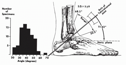
Figure 10.53 Variations in inclination of axis of subtalar joint as projected upon sagittal plane. The single observation of an angle of almost 70 degrees was present in a markedly cavus foot. (Inman TV. The Joints of the Ankle. Baltimore: Williams & Wilkins; 1976:37.)

The turning in of the heel was termed endorotation of the calcaneus by Lewis and the reverse was termed exorotation.53 For the clinician, exorotation of the calcaneus corresponds also to valgus of the heel and endorotation to varus.

Manter, in his study of the motion around the subtalar axis, recognized and measured a longitudinal displacement along the axis and described the motion at the subtalar joint as that of a screw.50 He compared the posterior calcaneal surface to the helical surface of a screw. Serial sections of this calcaneal surface made perpendicular to the subtalar joint axis revealed spiral rather than circular arcs. He considered this surface as being an “oblique helicoid, or screw-shaped surface.” He measured the helix angle of the posterior calcaneal surface by dropping a perpendicular line from a point on the axis to the articular surface (Fig. 10.59). The average helix angle was found to be 12 degrees. In pronation, the calcaneus, being held fixed, the talus advances along the subtalar axis approximately 1.5 mm for each 10 degrees of rotation at the joint. Van Langelaan measured also the helical motion at the subtalar joint.3 The axial translation of the talus was 1.7 mm (range, 1 to 2.6 mm) in a posterolateral direction during the exorotation of the leg of 30 degrees. Manter described the subtalar joint behavior “like a right-handed screw in the right foot and like a left-handed one in the left foot” (Fig. 10.60).50 The calcaneus advances along the subtalar axis during supination-adduction-flexion or varus of the heel and retreats along the same axis during pronation-abduction-extension or valgus of the heel.

The subtalar range of motion is variable, as indicated in Table 10.5. For the clinician, 25 to 30 degrees of inversion and 5 to 10 degrees of eversion is a practical average range of motion. During the stance phase of the gait on even ground, the heel strikes with minimal inversion at the subtalar joint, followed by eversion ranging from 5 to 10 degrees at 10% of the walking cycle. From there on, inversion occurs at the subtalar joint, reaching a maximum of 5 degrees at 62% of the walking cycle.


Multiple Axes of Motion

Van Langelaan, in an x-ray photogrammetric study of ten cadaver leg-foot preparations with incorporated metal markers, determined the polyaxial helical nature of the tarsal—including subtalar—motions.3 The extremities were loaded with 120 N weight (12.24 kg) and subjected to 30 to 35 degrees of external rotation, and the joint axes and motions were determined.

The subtalar motion was analyzed as being helical with continuous change in the position of the axes and thus forming a discrete bundle of axes (Fig. 10.61). A resultant single axis of the subtalar joint had an average angle of inclination of 41.4 degrees (range, 27 to 54.9 degrees) relative to the horizontal plane and an average angle of deviation of 22.2 degrees (range, 7 to 35.8 degrees). With 30 degrees of external rotation of the leg, the talus rotated 23.6 degrees (range, 15.5 to 30 degrees) in “abduction-eversion,” corresponding to abduction-pronationextension, and shifted along the subtalar axis in a posterolateral direction of 1.7 mm (range, 1 to 2.6 mm).


Motion and Stability

The motion at the subtalar joint is guided by the contour of the articular surfaces, their orientation, and the intrinsic and extrinsic ligaments.

The posterior calcaneal surface has been considered as a segment of a cone with the axis of the revolution of the surface directed anteromedially, intersecting the sustentaculum tali at nearly a right angle in the adult.9 Manter considered the posterior calcaneal surface as an oblique helicoid or screw-shaped surface.50 Inman demonstrated a screwlike behavior of the surface in 58% of 42 specimens and concluded that “the remarkable variation is the important factor.”10 Huson stressed the strong curvature of this surface medially forming a “bottleneck,” whereas the lateral segment of the surface has a lesser curvature.8

The posterior talar articular surface is quadrilateral, usually rectangular medially and more or less oval laterally. The surface is strongly concave in the long axis and usually flat or minimally concave transversely. From a functional point of view, the posterior calcaneal articular surface may be considered as a male ovoid surface and the posterior talar articular


surface as a female ovoid surface. The combined anterior and middle calcaneal surfaces form a female ovoid surface and the inferior articular surface of the talar head forms a male more or less flattened ovoid surface. MacConaill and Basmajian analyzed the motion components generated by the moving ovoid surfaces relative to each other.30 A male ovoid surface moving on a female ovoid surface slides, rolls, and spins. The rolling is in a direction opposite to the sliding (Fig. 10.62). A female ovoid surface moving on a male ovoid surface slides, rolls or rocks, and spins. The rolling is in the direction of sliding (Fig. 10.63). The roll is a tilt that maintains the surface contact and the spin maximizes the congruency. Huson analyzed the spin at the posterior talocalcaneal joint.8 Because of the differential of the curvatures of the articular surface—more curved medially and less curved laterally—a pure sliding creates more incongruency of the corresponding surfaces, whereas an associated spin minimizes the incongruency (Fig. 10.64). This interpretation is inclusive in the broader and more comprehensive analysis of the movement of ovoid surfaces presented by MacConaill and Basmajian.30 If the ovoid surfaces are obliquely oriented with regard to the long axis of the foot, the generated motion will have two components. The associated spin creates the third motion component.


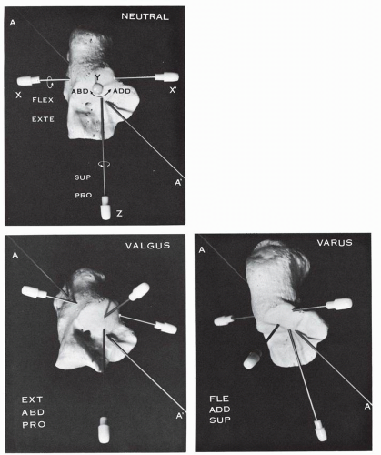
Figure 10.54 The axis of the talocalcaneonavicular joint AA′ as indicated passing through the os calcis in neutral position. The axis AA′ has three components: XX, which generates flexion-extension (FLEX-EXTE); Y, which generates abduction-adduction (ABD-ADD); Z, which generates supinationpronation (SUP-PRO). In valgus position the anterior aspect of the os calcis is simultaneously extended, abducted, and pronated. In varus position the anterior aspect of the os calcis is simultaneously flexed, adducted, and supinated.


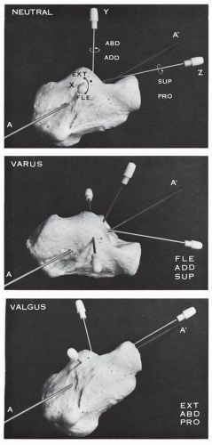
Figure 10.55 Axis of the talocalcaneonavicular joint AA′ seen in lateral view with the secondary axes X, Y, Z. The middle figure indicates the os calcis in varus and demonstrates the flexion (FLE) and supination (SUP) components. The bottom figure indicates the os calcis in valgus and demonstrates the components of extension (EXT) and pronation (PRO). (ABD, abduction; ADD, adduction.)


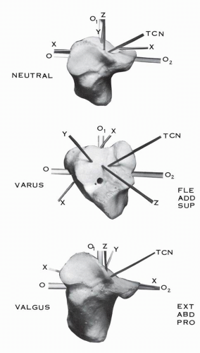
Figure 10.56 Frontal view of the os calcis. In varus of the heel the anterior aspect of the os calcis is flexed (FLE), adducted (ADD), and supinated (SUP). In valgus of the heel the anterior aspect of the os calcis is extended (EXT), abducted (ABD), and pronated (PRO). (TCN, talocalcaneonavicular axis; XX, transverse axis of flexion-extension; Y, vertical axis of abduction-adduction; Z, longitudinal axis of supination-pronation; O, O1, O2, cruciform reference line.)


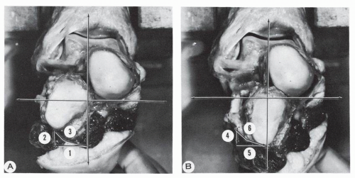
Figure 10.57 Anatomic model of the hindfoot. (A) Valgus position of the os calcis involving (1) abduction, (2) extension, (3) pronation. (B) Varus position of the os calcis involving (4) flexion, (5) adduction, (6) supination.


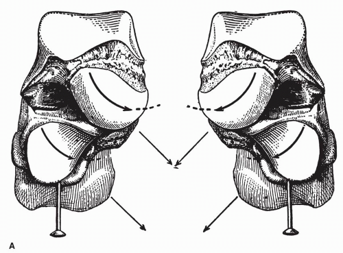
Figure 10.58 (A) Relationship of the talus and the calcaneus in the standing position as indicated by the vertical pin inserted in the calcaneus. The posterior calcaneal surface is covered by the external apophysis of the talus. The “condylar” surface of the talus is medial relative to the “trochlear” surface of the calcaneus. The long axis of the talar condylar surface is parallel to the long axis of the trochlear surface of the cuboid. Both axes are directed inferiorly, medially, and posteriorly, and this allows an “oblique flexion inwards.”


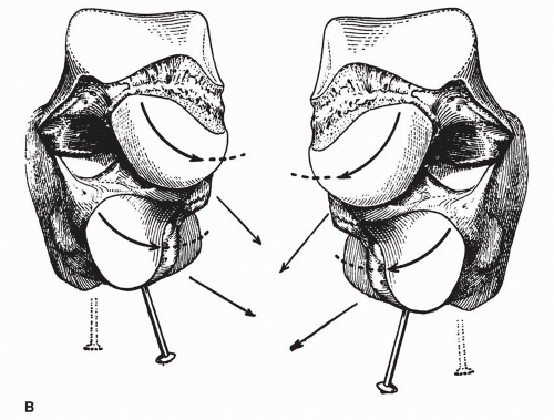
Figure 10.58 (Continued) (B) The talus has remained unchanged. The calcaneus is turned inward, as evidenced by the obliquity of the calcaneal pin. The long axes of the talar condylar and calcaneal trochlear surfaces are convergent. This corresponds to the “physiologic varus of flexion + adduction + supination,” which results from the combined movements of the navicular on the talus, the cuboid on the calcaneus, and the calcaneus on the talus. (From Farabeuf LH. Precis de Manuel Opératoire. Paris: Maisson; 1889:827.)


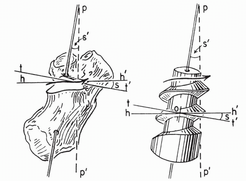
Figure 10.59 Comparison of the posterior calcaneal facet of the right subtalar joint with a right-hand screw. Arrow represents the path of a body following the screw. hh′ is the horizontal plane in which motion is occurring. tt′ is a plane perpendicular to the axis of the screw. s is the helix angle of the screw, equal to the angle s′, which is obtained by dropping a perpendicular pp′ from the axis. (Manter JT. Movements of the subtalar and transverse tarsal joints. Anat Rec. 1941;80:402.)


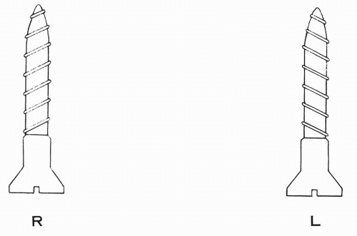
Figure 10.60 Right-hand and left-hand screws.


TABLE 10.5 REPORTED RANGES OF SUBTALAR MOTION


Author


Range of Motion


Manter (1941)


10 to 15 degrees


Hicks (1953)


24 degrees


Close and colleagues (1967)


9.9 to 28 degrees


Inman (1976)


10 to 65 degrees (average, 40 degrees 6 7 degrees)


MacMaster (1976)


30 degrees (25 degrees inversion, 5 degrees eversion)


American Medical Association (1988)


50 degrees (30 degrees inversion, 20 degrees eversion)


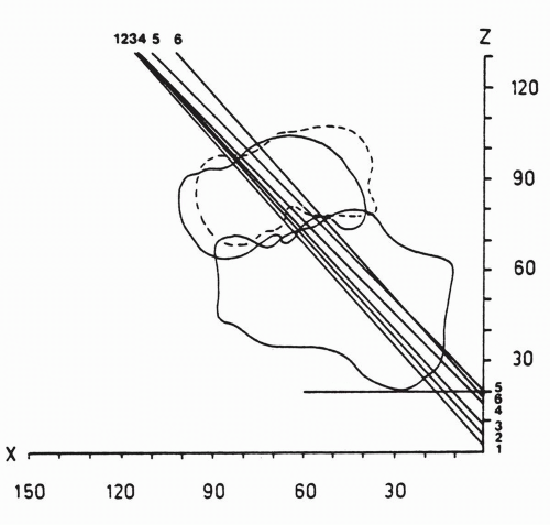
Figure 10.61 Relative talocalcaneal helical axes with 10 degrees of talocalcaneal exorotation projected on sagittal plane. (Van Langelaan EJ. A kinematical analysis of the tarsal joints. An X-ray photogrammetric study. Acta Orthop Scand. 1983;54[Suppl 204]:147.)

More specifically, the posterior calcaneal articular surface is oriented obliquely from posteromedial to anterolateral. Furthermore, the posterior segment is more dorsal and the anterior segment of the surface is more plantar. A female ovoid surface moving along this surface will naturally flex or extend and at the same time will supinate-pronate. Theoretically, a convex male surface oriented transversely will generate only the motion of flexion-extension, whereas such a surface oriented longitudinally will generate only the motion of supination-pronation. The oblique orientation of the posterior calcaneal surface will generate a combination of both flexion-extension and supination-pronation (Fig. 10.65). The inescapable spin creates the third motion component present at this joint: adduction-abduction. In “reading” into the contour and orientation of the posterior talocalcaneal joint, we can now clearly see that the generated motion is that of flexion-supination-adduction or extension-pronation-abduction. The talus and the calcaneus move in opposite directions to reach the end-position. In the clinician’s “valgus” of the heel, the calcaneus moves in extension-pronation-abduction or the talus moves in flexion-supination-adduction. In “varus,” the calcaneus is in flexion-supination-adduction and the talus moves in extension-pronation-abduction (Fig. 10.66).


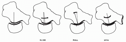
Figure 10.62 A male ovoid surface (posterior calcaneal articular surface) moving on a female ovoid surface (posterior talar articular surface) slides, rolls, and spins. The rolling is in a direction opposite to the sliding. The sliding advances the moving surface but creates a gap that is closed by the reverse rolling, and the maximum surface contact is achieved by the spinning of the moving surface. (Concept of MacConaill and Basmajian.)


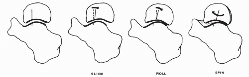
Figure 10.63 A female ovoid surface moving on a male ovoid surface slides, rolls, and spins. The rolling is in the direction of the sliding.


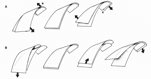
Figure 10.64 Diagrammatic representation of the posterior calcaneotalar articular surfaces. The posterior calcaneal surface has “convex profiles lying in a medial, backward and upward direction. The curvatures grow stronger in the same direction and in addition the profiles of the medial and anterior part of the facet, bordering on the canalis tarsi, are more curved than the lateral ones. Such surfaces in gliding over each other will show great discongruencies when they follow their strongest or weakest curvatures,” as seen on the lower diagrams (B). “If this shift is simultaneously combined with a turn the discongruencies are limited to a circumscribed part (indicated by the asterisk) of the articular surfaces,” as seen on the upper diagrams (A). (Huson A. Anatomical and Functional Study of the Tarsal Joints. Leiden: Drukkerij, “Luctor et Emergo”; 1961:137.)

The degree of orientation of the articular surfaces affects the amplitude of the motion components. The posterior calcaneal surface has an inclination angle with an average of 65 degrees, a minimum of 55 degrees, and a maximum of 75 degrees relative to a line drawn along the superior surface of the calcaneal body. A larger inclination angle provides more flexion component to the motion (Fig. 10.67). The posterior talar articulating surface has a declination angle with an average of 37 degrees, a minimum of 26 degrees, and a maximum of 50 degrees relative to the anterior trochlear line. A greater declination angle orients the surface in a longitudinal direction that will increase the flexion-extension component, whereas a smaller declination angle orients the surface more transversely and increases the supination-pronation component (Fig. 10.68).

MacConaill and Basmajian consider the subtalar joint as a bicondylar joint between the talus and the calcaneus, and the “rotation of one or the other of the mating bones can take place around an axis between the condyles.”30 This axis of motion is indeed located and passes through the canalis tarsi and the medial segment of the talocalcaneal interosseous ligament. Farabeuf stressed the rotational motion of the talus in a “tourniquet” fashion over the os calcis, or vice versa, taking place around a center located in the innermost part of the canalis tarsi through a twisting of the fibers of the interosseous ligament.52 He clearly demonstrated this rotation on his diagram (Fig. 10.69).


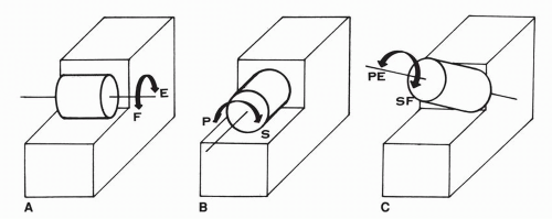
Figure 10.65 (A) A convex male surface oriented transversely generates the motion of flexion (F) and extension (E). (B) A convex male surface oriented longitudinally generates the motion of pronation (P) and supination (S). (C) A convex male surface oriented obliquely—as indicated—generates a combination of pronation-extension (PE) and supination-flexion (SF).

The fibers of the talocalcaneal interosseous ligament are oriented upward, medially, and anteroposteriorly. The lateral fibers are longer and have more excursion laterally, whereas the shorter fibers on the inner side have less excursion. The cervical ligament originates on the calcaneal surface of the sinus tarsi and is oriented upward, anteriorly, and medially to insert on the talar neck. This arrangement of the ligaments promotes—as qualified by Huson—a “swinging motion” with a center of movement located along the short medial fibers of the ligament of the canalis tarsi.8 The cervical ligament remains tight in both exorotation (valgus) and endorotation (varus) of the heel. The
talocalcaneal interosseous ligament of the canalis tarsi and the cervical ligament may be considered as cruciate ligaments of the subtalar joint, as determined by their opposite orientation. The cervical ligaments and the calcaneofibular ligament have an approximate similar orientation.


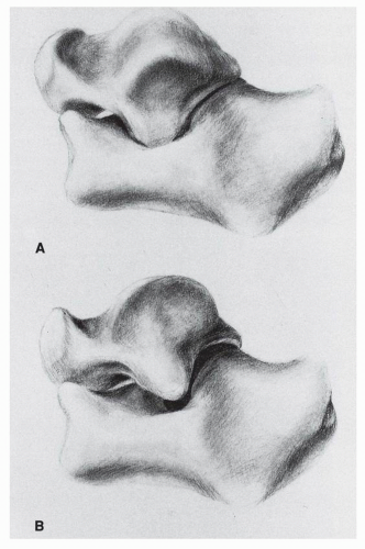
Figure 10.66 (A) Valgus of the heel: The calcaneus being held fixed, the talus moves in flexion-supination-adduction. The lateral process of the talus is low and strikes Gissane’s angle of the calcaneus. If the talus is held in neutral, then the calcaneus is in extension-pronation-abduction. (B) Varus of the heel: The calcaneus being held fixed, the talus moves in extension-pronation-abduction. The lateral process of the talus is high in position in the sinus tarsi. If the talus is held in neutral, then the calcaneus is in flexion-supination-adduction.

The bony stability of the subtalar joint or close-pack position is achieved with exorotation or valgus of the calcaneus. In this position there is maximum contact and near congruous fit at the posterior talocalcaneal joint. The talar lateral process descends and advances on the posterior calcaneal surface and the solid talar wedge or male V fits into the female V of the calcaneal surface. With endorotation or varus of the calcaneus, the sustentaculum talus moves toward the posteromedial tubercle of the talus and considerably narrows the medial opening of the canalis tarsi.

The talar lateral process is now dorsal on the corresponding calcaneal surface. This anatomic relationship laterally allows the clinician to recognize the valgus or varus position of the hindfoot roentgenographically. The cervical ligament and the inferior extensor retinaculum limit the endorotation of the calcaneus.54 The talocalcaneal interosseous ligament of the canalis tarsi remains tight during the endo- and exorctation of the calcaneus.8, 54 Smith, however, considers the talocalcaneal ligament of the canalis tarsi as limiting the exorotation or eversion of the calcaneus.

Tochigi et al.55 analyzed five fresh frozen cadaver lower extremities (ages 25 to 85 years) for the three-dimensional movement of the talus and calcaneus relative to the tibia under axial loading from 89.8 to 686 N. The induced talar and subtalar motions were triaxial. When the axial load was increased from 9.8 to 686 N, the maximum total ankle rotation averaged 3.5 degrees ± 1.2 degrees with plantar flexion 2.6 degrees ±1.1 degrees, adduction 2.1 degrees ±1.0 degrees, and negligible inversion 0.1 degrees ± 0.7 degrees. In the intact subtalar joint, under axial loading the induced motion was also triaxial. The total subtalar motion averaged 3.2 degrees ± 1.3 degrees, mostly eversion, with dorsiflexion 0.8 degrees ±0.9 degrees and abduction 0.8 degrees ±1.0 degrees.

The ankle rotation did not significantly change after isolated sectioning of the anterior talofibular ligament. After the combined sectioning of the interosseous talocalcalcaneal and anterior talofibular ligaments the maximum ankle joint rotation averaged 5.2 degrees ± 1 degrees, whereas plantar flexion averaged 4.0 degrees ± 0.9 degrees, and adduction 3.3 degrees ±0.8 degrees.

Tochigi et al.56 investigated the load-displacement characteristics of the subtalar joint in six cadaver specimens, using an axial distraction test and a transverse multidirectional drawer test. Cyclical loading (± 60 N) was applied and loaddisplacement responses were collected before and after cutting the interosseous talocalcaneal ligament. The results confirmed the role of the interosseous talocalcaneal ligament in maintaining apposition at the subtalar joint suggesting that interosseous talocalcaneal ligament failure causes inversion instability of the subtalar joint. They also suggested the role of the interosseous talocalcaneal ligament in stabilizing the subtalar joint against drawer forces applied to the calcaneus from lateral to medial. The authors suggested examining a patient with possible subtalar instability with a drawer force applied “along the preferential axis roughly from the posterior aspect of the fibula to the central region of the medial malleolus.”56

Fujii et al.57 assessed the mechanical characteristics of the ankle-hindfoot complex in 13 cadaver specimens mounted in a testing apparatus. A constant rotational force in the form of inversion-eversion, internal-external rotation was applied throughout the entire range of the ankle sagittal plane and the resulting calcaneo-tibial motion was measured.

With inversion force applied, the calcaneotibial inversion was greatest in maximal plantar flexion (mean 22.1 degrees ± 6 degrees) and gradually decreased with dorsiflexion. With eversion force applied, the calcaneotibial eversion gradually increased with increasing dorsiflexion to 12.7 degrees ± 7.4
degrees. With internal rotation force applied, calcaneotibial rotation increased from plantar flexion to neutral ankle position. With external rotation force applied, calcaneotibial external rotation from neutral to maximal dorsiflexion increased. Their conclusion was that “the ankle is less stable in plantarflexion when inversion and internal rotation forces are applied” and “the ankle was less stable in dorsiflexion when eversion and external rotational forces were applied.”


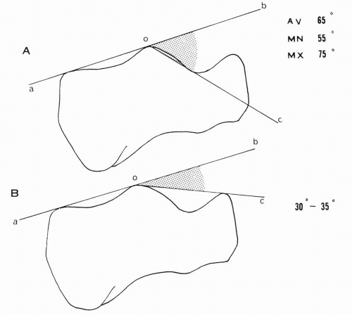
Figure 10.67 (A) Inclination angle of the posterior calcaneal surface. (B) Boehler’s angle.

Kjaersgaard-Andersen and colleagues determined experimentally the stabilizing effect of the ligamentous structures in the sinus and canalis tarsi at the subtalar joint.58 In 20 cadaveric specimens, the total range of motion was measured at the subtalar joint and the subtalar-ankle joint complex.

A continuous movement was obtained by applying a constant torque and moment of 1.5 N · m. This resulted in a force transmission to the subtalar joint of 10 N (or 1.02 kg). The movement was recorded and computer analyzed in three planes. The study was conducted first in the intact specimens. In 10 specimens the motion was assessed after transection of the cervical ligament. In another 10 specimens the motion was assessed after transection of the talocalcaneal interosseous ligament of the canalis tarsi.

In the first 10 specimens, the median movement at the talocalcaneal joint was 15.5 degrees in neutral. This small range of motion may be explained by the fact that the applied force was minimal (1 kg) and the specimens may have been obtained from an older age group. Lang and Wachsmuth have demonstrated indeed that with aging the field of motion of the foot contracts in the transverse segment.9

After transection of the cervical ligament, the increase of motion was as follows:


In the horizontal plane (internal-external rotation): 10% In the frontal plane (pronation-supination): 14%. This motion

is termed adduction-abduction by the authors. In the sagittal plane (dorsiflexion-plantar flexion): 20%.


In the second group of 10 specimens, the median movement at the talocalcaneal joint with an intact ligament was 11.9 degrees in neutral.

After transection of the talocalcaneal ligament of the canalis tarsi, the increase in the range of motion was as follows:

In the horizontal plane (internal-external rotation): 21% In the frontal plane (pronation-supination): 16% In the sagittal plane (dorsiflexion-plantar flexion): 57%, with 43% of the increase in dorsiflexion and 14% in plantar flexion.


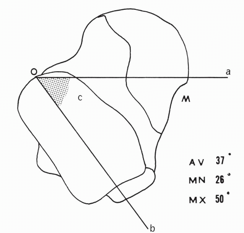
Figure 10.68 Declination angle of the posterior talar articular surface.


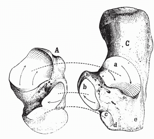
Figure 10.69 The rotational motion of the talus over the calcaneus. The arrows indicate the direction of rotation in a “tourniquet” fashion around the axis of rotation X located in the canalis tarsi. (A, talus; C, calcaneus; a, posterior calcaneal articular surface, cone shaped; b, sustentacular surface; c, anterior calcaneal surface.) (Farabeuf LH. Precis de Manuel Opératoire. Paris: Maisson; 1889:818.)

This study is suggestive of the more important stabilizing role of the talocalcaneal ligament of the canalis tarsi limiting the exorotation or valgus of the calcaneus.

The stabilizing role of the ankle ligaments in subtalar motion was also investigated by Kjaersgaard-Andersen and colleagues in two different studies.59, 60

The role of the tibiocalcaneal fascicle of the deltoid ligament was analyzed in ten cadaveric ankle-feet.59 A torque or moment of 1.5 N · m was applied with an effective force of 10 N (1 kg) acting on the joint. Data were obtained from continuous movement curves and subjected to computer and statistical analysis. The motion was registered in three planes. After immobilization of the ankle joint with an external fixator, the talocalcaneal motion was assessed before and after transection of ligaments. The external fixator was removed and the total range of motion was assessed again.

The median percentage of increase of motion at the subtalar joint after transection of the tibiocalcaneal fascicle of the deltoid ligament was as follows:


In the horizontal plane (internal-external rotation): 12%, with 10% in external rotation and 2% in internal rotation

In the frontal plane (pronation-supination): 31%, with 30% in pronation and 1% in supination. This motion is termed abduction-adduction by the authors.

In the sagittal plane (dorsiflexion-plantar flexion): 40%, with 30% plantar flexion and 10% dorsiflexion.

It is apparent that the transection of this ligament results in an increase in plantar flexion, pronation, and external rotation at the talocalcaneal joint.

The motion increased also at the combined tibiotalocalcaneal joint complex, mainly in pronation, external rotation, and plantar flexion, indicating the supportive role of the ligament at the ankle joint also.

Using the same methodology, Kjaersgaard-Andersen and colleagues analyzed the role of the calcaneofibular ligament with regard to the motion at the subtalar joint.60 Ten cadaveric ankle-foot preparations were used. A torque or moment of 1.5 N · m was applied and the mobility of the talocalcaneal and tibiotalocalcaneal joint was assessed on the intact specimens and after sectioning the calcaneofibular ligament.

The motion in the frontal plane or supination (termed adduction by the authors) was assessed at different degrees of dorsiflexion-plantar flexion. After sectioning of the calcaneofibular ligament, the mean increment of supination at the combined tibiotalocalcaneal joint complex was 3 to 7 degrees, increasing from the plantar-flexed position to maximum dorsiflexion (Fig. 10.70). The mean increment of supination at the subtalar joint was 3.1 to 4.6 degrees, increasing from 5 degrees of plantar flexion to 5 degrees of dorsiflexion (Fig. 10.71). This study demonstrated the importance of the calcaneofibular ligament in determining the lateral stability of the subtalar joint.

This finding is contrary to that of Cass and coworkers, who detected no influence of the calcaneofibular ligament on subtalar supination (author’s adduction), which remained constant in plantar flexion or dorsiflexion.42

The variability of the orientation of the calcaneofibular ligament, as analyzed by Ruth, may contribute to the explanation
of these functional discrepancies.32 Furthermore, the functional implication of the variable anatomic relationship between the calcaneofibular ligament and the lateral talocalcaneal ligament was investigated by Trouilloud and colleagues in 26 ankles.61 They divided their specimens into three types: A, B, and C. In type A (35%), a lateral talocalcaneal ligament blends with or reinforces intimately the calcaneofibular ligament and diverges from the latter at the talar or at the calcaneal insertion. In type B (23%), a distinct lateral talocalcaneal ligament is present just anterior to the calcaneofibular ligament. In type C (42%), the lateral talocalcaneal ligament is absent.


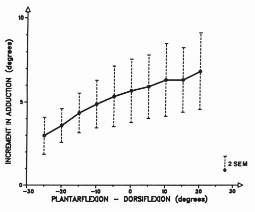
Figure 10.70 Mean increments of adduction (or supination) at the tibiotalocalcaneal joint complex after section of the calcaneofibular ligament in ten specimens. (Kjaersgaard-Andersen P, Wethelung J-O, Nielsen S. Lateral talocalcaneal instability following section of the calcaneo-fibular ligament: A kinesiologic study. Foot Ankle. 1987;7[6]:358.)


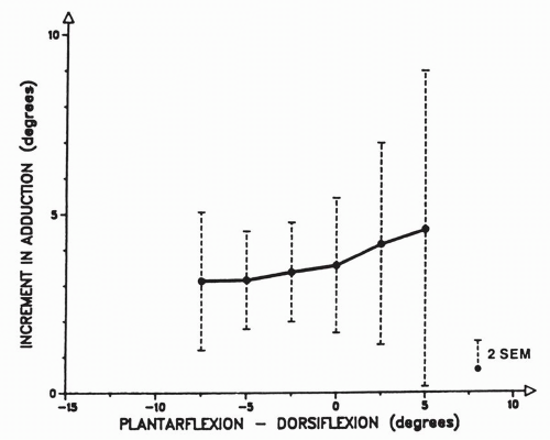
Figure 10.71 Mean increments of adduction (or supination) at the talocalcaneal joint after section of the calcaneofibular ligament in ten specimens. (Kjaersgaard-Andersen P, Wethelung J-O, Nielsen S. Lateral talocalcaneal instability following section of the calcaneo-fibular ligament: A kinesiologic study. Foot Ankle. 1987;7[6]:359.)

The transection of the calcaneofibular ligament in type B did not affect the subtalar or the talocalcaneonavicular motions, whereas in types A and C it affected the subtalar motion, resulting in the author’s interpretation of a talonavicular subluxation.

Martin et al.62 investigated the elongation behavior of calcaneofibular and cervical ligaments during inversion loads in nine cadaver specimens (ages range 63-81 years). Two methods
of inversion assessment were used: manual and roentgenographic. Under inversion load with the calcaneofibular ligament intact the mean elongation of the cervical ligament was 0.58 mm ±0.33 mm by manual measurement and 0.46 mm ± 0.23 mm by x-ray measurement. With the calcaneofibular ligament transected, under inversion load, the elongation of the cervical ligament was 0.88 mm ±0.37 mm by manual measurement and 0.78 mm ±0.37 mm by x-ray measurement. With the transection of the calcaneofibular ligament, the inversion range of motion increased 7.5 degrees ± 2.75 degrees manually and 7.7 degrees ±2.95 degrees by x-ray measurement.


Midtarsal Joint Motion: Calcaneocuboid, Talonavicular, and Cubonavicular

The midtarsal joint—transverse tarsal joint or Chopart’s joint—is formed by the calcaneocuboid and the talonavicular joints. A functional unit is formed by the cuboid and the navicular, which form an amphiarthrosis and move upon the anterior calcaneal surface and the talar head. Manter has described two axes to the midtarsal joint: longitudinal and transverse (Fig. 10.72).50

The longitudinal axis passes through the posterolateral aspect of the calcaneus and the beak of the cuboid, and is directed from posterolaterally to anteromedially. This axis slopes upward anteriorly 15 degrees and is medially deviated 9 degrees. With the calcaneus held fixed, the movement around this axis is that of pronation-supination, with some abduction associated with pronation and some adduction associated with supination. The motion around this axis is also helical, involving a screwlike action. The helix angle is 10 degrees. The direction of the screw is opposite that of the subtalar joint. It is left-handed in the right foot and right-handed in the left foot (Fig. 10.73). The second axis of the midtarsal joint is quite steep and oblique.


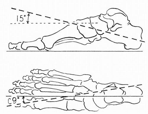
Figure 10.72 The longitudinal axis of the transverse tarsal joint projected in the sagittal and the horizontal planes of the foot. (Manter JT. Movements of the subtalar and transverse tarsal joints. Anat Rec. 1941;80:407.)


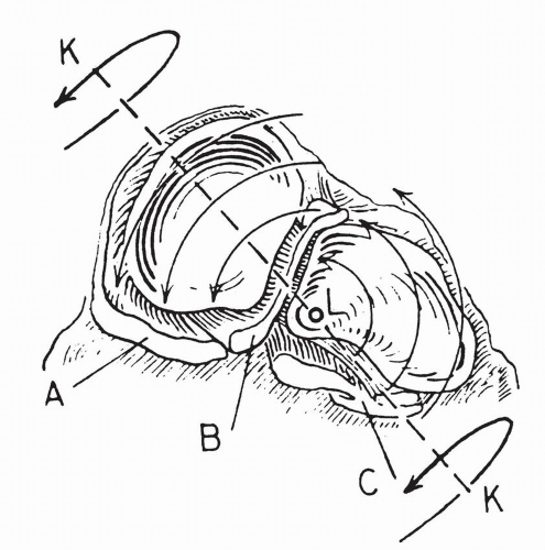
Figure 10.73 Posterior view of the right transverse tarsal joint shows the articular surfaces of the navicular and the cuboid. Light arrows indicate motion about a longitudinal axis L; heavy arrows indicate motion about an oblique axis KK. (A, plantar calcaneonavicular ligament; B, deep portion of the bifurcate ligament; C, long and short plantar ligaments.) (Manter JT. Movements of the subtalar and transverse tarsal joints. Anat Rec. 1941;80:404.)

The inclination angle is 52 degrees and the declination or medial deviation is 57 degrees. The motion generated is that of dorsiflexion-abduction or plantar flexion-adduction of the cubonavicular when the talus and the calcaneus are held fixed. No helical motion was detected along this axis.

Hicks also describes two axes to the midtarsal joint: oblique and longitudinal (Fig. 10.74).12 The longitudinal axis is directed from the inferior aspect of the navicular to the posterolateral aspect of the heel. It slopes upward anteriorly. The major motion occurring around this axis is pronation with slight abductionextension and supination with slight adduction-flexion. The range of motion is 8 degrees.

The oblique axis is directed from the superomedial aspect of the talar head to the inferolateral aspect of the heel. This axis generates the motion of pronation-abduction-extension and of supination-adduction-flexion. The range of motion is 22 degrees.

May 28, 2016 | Posted by in ORTHOPEDIC | Comments Off on Functional Anatomy of the Foot and Ankle

Full access? Get Clinical Tree

Get Clinical Tree app for offline access