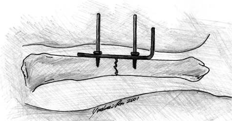
Chapter 6 Most orthopaedic surgeons are not familiar with the history of bone fixation, and the literature on the issue is scant (either old or out of print). The authors had a difficult time trying to learn the historical development of osteosynthesis and found only a few publications on the topic. These are listed in the reference section for serious readers.1–7 The earliest technique of internal fixation of bone fractures was probably ligature or wire used in 1775 by Lapuyade and Sicre, surgeons from Toulouse.4,6 Other confirmed cases were the successful wiring of an un-united humeral fracture in 1827 by J. H. Rodgers of New York,6,8 fixation of an open humerus fracture with threaded suture in 1839 by Flaubert of Rouen,9 and fixation of a comminuted lower leg fracture using lead wire in 1851 by Dr. Long of Toulon.1,4 The use of screws for fixation in bone probably started in the late 1840s. In 1850, Cucuel and Rigaud described the use of screws for management of two fracture cases, a sternum fracture and an olecranon fracture.4–6 The first documented application of a plate for bone fixation was made by Hansmann in 1886.2,4 The plate was made of metal and was L-shaped with six screw holes. The plate was inserted into the fracture site through a skin incision and fixed to the bone across the fracture line. The screws were also inserted through the skin for easy removal. When the bone healed, the plate was pulled out by holding the part that had been left out of the skin (the bent end of the plate) (Fig. 6–1). Albin Lambotte (1866–1955), a Belgian surgeon, is generally regarded as the father of osteosynthesis due to his pioneering work and tremendous contribution to the field.4,5 It was Lambotte who coined the term “osteosynthesis.” Through the 19th century, osteosynthesis was further developed and perfected by several famous surgeons, including W. Arbuthnot Lane, W. O. Sherman, and later, in the 1940s, Robert Danis (1880–1962).5 FIGURE 6–1 The first bone plate by Hansmann in 1886. Robert Danis was regarded as the father of modern internal fixation.4 His three objectives of osteosynthesis3 (immediate mobilization of the injured limb, anatomical restoration of fractured bone, and primary bone healing) set the foundation for the late Arbeitsgemeinschaft für Osteosynthesefragen (AO) technologies developed by Maurice Müller in the 1960s.10 In the 1960s AO, headed by Müller, introduced its basic principles of fracture treatment: anatomical reduction, stable internal fixation, and early mobilization. More recently, plating methods have focused on the principles of “biological fixation.” These methods attempt to preserve the blood supply for improving the rate of fracture healing, decreasing the need for bone grafting, and decreasing the incidence of infection and refracture.7 According to the literature, little attention has been paid to the fixation of osteoporotic bone until recently.11 To briefly review the history, major methods for managing osteoporotic or mechanically compromised bone are listed in Table 6–1. Many methods are covered in other chapters in this book. The purpose of this chapter is to highlight major principles and methods in the field.
CURRENT METHODS AND TRENDS
IN FIXATION OF OSTEOPOROTIC BONE
| Principle | Features | Early Publications (First Author, Year, Reference) |
|---|---|---|
| Screws, anchor, nuts | ||
| Expansion bolt/screws | Improved bone purchase | Lesoin 1983,12 Sell 1989,13 Cook 200014 |
| Cementing screws | Enhanced screw fixation | McKoy 2000,15 Broos 2000,16 Chs. 21, 22 |
| Interlocking screws | Enhanced screw fixation | McKoy 2000,17 Ch. 20 |
| Swellable bone anchor | Improved bone purchase | Nien 2001,18 Richter 199919 |
| Hollow wall anchor | Pullout resistant | McKoy 200120 |
| POR nut | Prevents screw pullout | Lieberman 199821 |
| Schuhli nuts | Improved cortical purchase, preserves blood supply | Kolodziej 1998,22 Ring 199923 |
| Plates | ||
| Adhesive plate | Prevents motion between the plate and the bone, reduces stress protection | Meyrueis 197724 |
| Mennen plate | Preserves blood supply, reduces stress protection | Mennen 1981,25 198926 |
| LC-DCP | Preserves blood supply, reduces cortical porosity | Perren 1991,27 Klaue 1991,28 Ch. 25 |
| MCP | Preserves blood supply, reduces stress protection | Abel 199829 |
| PC-Fix | Prevents motion between the plate and the bone, reduces stress protection, preserves blood supply | Tepic 1992,30 Miclau 199531 |
| Zespol plate | Preserves blood supply, fixed angle | Ramotowski 199132 |
| LISS | Preserves blood supply, reduces stress protection | Fankhauser 1999,33 Schandelmaier 199934 |
| IM nails | ||
| Expandable IM nail | Good bone reduction | Shasha 1999,35 Ch. 30 |
| Rectangular IM nail | Fits large IM canal, rotational stability | Wu 199136 |
| Zickel nails | Rotational stability | Zickel 197737 |
| Cement | ||
| With metal devices | Enhanced stability of metal implants | Cameron 1975,38 Schatzker 1975,39 Harrington 1975,40 Muhr 1979,41 Bartucci 198542 |
| Vertebroplasty | Mechanically compromised bone | Galibert 1987,43 Kaemmerlen 198944 |
Abbreviations: POR nut, pullout resistant nut; LISS, less invasive stabilization system; LC-DCP, limited contact dynamic compression plate; PC-Fix, point contact fixator; MCP, minimum contact plate.
CHARACTERISTICS OF OSTEOPOROTIC BONE
The biochemical and cellular defects associated with osteoporosis lead to structural changes in bone that are particularly applicable when considering traumatic fractures and their repair. Osteoporotic bone is characterized not only by a decreased amount of bone, but also by alterations in the architecture and composition of the affected osseous tissues.45,46 Structural changes predictably affect the physical properties of bone by lowering the level of maximum tolerable stress, decreasing elasticity, and reducing the potential for energy absorption.45 The final result is a bone that is not only thin but also weak and brittle. Besides being more susceptible to incurring fractures, patients with osteoporosis tend to have significant difficulty associated with fracture fixation, more postoperative complications, and longer recovery times.47,48
The most constant feature of osteoporotic bone is a decrease in bone density. In fact, the World Health Organization defines osteoporosis as having bone mass 2.5 standard deviations below the mean bone density.49 An average person’s bone mineral density decreases by 50% between the ages of 20 and 80, so any superimposed osteoporotic changes could easily lower a patient’s bone density to a critical level.45 Bone density appears to be the major factor linked to the biomechanical functioning of osteoporotic bone. Studies have shown that a decrease in bone density is associated with a decrease in maximal stress tolerance, elasticity, and energy absorption.45 In other words, density is directly related to the strength of bone. The loss of density is seen globally, affecting both cortical and cancellous bone, with the cancellous bone being affected to a much greater degree.47
The second aspect of bone that is affected by osteoporosis is the microarchitecture of the tissue itself. As osteoporosis decreases deposition and increases resorption of calcium, the trabecular framework of bone is affected. There is a decrease in cross-linking of subchondral bone, measured by the Singh Index. In this scale, bone quality is graded from 1 to 6 based on the trabecular bone pattern. Associated with the decrease in connectivity, there is a thinning of the trabeculae from resorption.45 So, not only are there fewer connections, but the existing ones are thinner than normal. The quality of these trabeculae is crucial to the interlocking of screws, pins, wires, or intramedullary nails.
This microarchitecture of bone tissues is critical because it determines the resistance to compressive forces. With increased thickness of the trabeculae and more cross-linking, bone is better able to withstand torsion and bending. Loading of bone plays an important role in maintaining structure and integrity. The stress absorbed by bone stimulates growth and maintenance of trabecular connectivity, ultimately increasing the cross-sectional area. Loading is actually an essential part of fracture repair and is lost when a patient becomes immobile from a fracture. Stable internal fixation allows patients to ambulate soon after surgery and begin this process of reforming and strengthening trabecular cross-links.
Along with these changes in microarchitecture, there are associated changes in the macroarchitecture as well. Osteoporotic bone has a thinner cortex and larger medullary canal than healthy bone. While the overall diameter of the long bones may remain the same, the ratio of cancellous to cortical bone is increased.50 The thin layer of cortex surrounding abundant cancellous bone is a weaker structural model and predisposes to low-energy fractures such as those through the femoral neck and greater trochanters. It is precisely these fractures that are most often seen in falls with the elderly. The abundance of cancellous bone will also adversely affect the fixation of osteoporotic fractures.
SCREWS
Fracture fixation is made possible through a vast variety of bone screws. Without screws, the use of many fixation devices, such as bone plates, intramedullary nails, and even some joint prostheses, would be less effective or even impossible. Each type of bone screw is uniquely designed for specific applications. The type of bone screw chosen most often depends on the general health of the bone at or near the fracture (normal versus osteoporotic), the location of the fracture (metaphysis, epiphysis, diaphysis), the density of bone (cortical versus cancellous), and the type and classification of fracture. Bone screws are designed around these parameters. Screws have many functions in orthopaedic surgery including bringing bone fragments together or fixing the fracture alone, fixing plate to bone, interlocking an intramedullary nail, working as anchors for wires, and fixing ligament or tendons to bone. This section will focus on common screw types and the relevance to internal fixation in osteoporotic bone.
TYPES OF SCREWS
There are numerous types of screws available today. Each style possesses unique advantages in different applications. Bone screws may be categorized as cortical or cancellous, self-tapping or non-self-tapping, solid or cannulated, and fully threaded or partially threaded.
Cortical vs. Cancellous
The basic types of screws common to the average individual are wood and metal screws, which are two basic types of screws employed to attach objects together in everyday applications. If these two types of screws are placed side by side, variations in design can be immediately observed (Figs. 6–2A,B). The wood screw generally possesses a smaller core with larger threads spaced farther apart than its metal counterpart. This is no accident. The wood screw is used to penetrate materials with less density and resistance. The design of the wood screw offers deeper thread penetration, providing better stabilization in the wood. The metal screw, on the other hand, must have small threads closely spaced to pierce through the screw hole in the metal. This design does not provide as much thread penetration, but the small pitch assures that more threads are in contact with metal. It would not be possible to drive a wood screw with large threads into metal because the resistance would be too great. On the other hand, metal screws could be driven into wood, but the grip would not be nearly as strong and the screw would eventually fail (cut out) in most cases.
Similarly, cortical and cancellous bone screws possess different geometry based on the required function. The cancellous bone screw is analogous to the wood screw. It features larger, wider-spaced threads and a smaller core diameter. This enables the screw to easily penetrate and obtain a strong grip in less dense cancellous bone located in the metaphyseal and epiphyseal regions of long bones. On the other hand, cortical bone most commonly located in the diaphyseal areas is analogous to metal in terms of density and resistance to penetration. Hence, smaller threads spaced closely together enable penetration while still maintaining a solid grip. As in the “real-life” example, it would not be possible to screw a cancellous bone screw into cortical bone. Similarly, a cortical screw could rather easily be driven into cancellous bone. However, the small threads would provide a limited grip in the less dense trabecular bone, and the screw would most likely be pulled out over time. Images of cortical and cancellous bones depicting the variation in thread size and quantity are shown in Figures 6–3A,B.
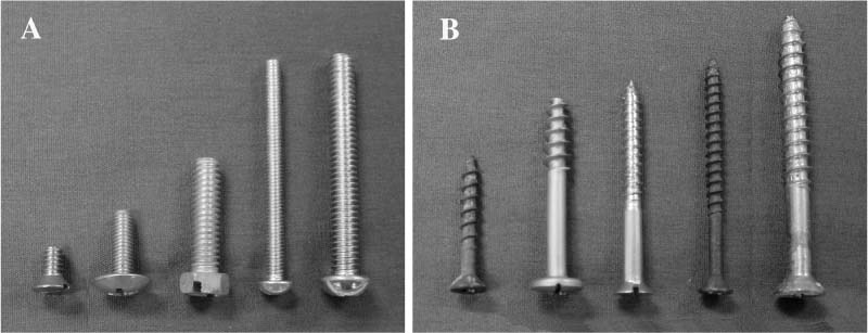
FIGURE 6–2 (A) Metal screws and (B) wood screws.
Cortical screws are fully threaded screws commonly used to attach plates to bone. Cortical screws may be used as lag screws if the near cortex is over-drilled. This technique allows the threads near the head of the screw to turn freely in the guide hole and the threads in the far cortex to take purchase and produce compression between the near and far cortexes.
Self-Tapping vs. Non-Self-Tapping
Depending on the nature of the fracture and the type of bone, surgeons may elect to employ self-tapping (Fig. 6–4) or non-self-tapping bone screws. For self-tapping screws, the surgeon first prepares a pilot hole using a drill bit slightly larger than the screw’s core diameter but smaller than the outer diameter of the threads. The screw is then driven into the pilot hole as the threads cut a shallow path into the cortex. Self-tapping screws are advantageous in thin cortical bone, according to Müller et al.10 However, these researchers recommend that self-tapping screws not be used in thick cortical bone due to the relatively high resistance they are subjected to. The large amounts of torque necessary to drive the self-tapping screw in cortical bone could result in the shearing of the screw or imprecise incision.
Non-self-tapping screws, on the other hand, do not cut their own path. After the pilot hole is drilled, a tap is used to cut deeper grooves matching the contour of the screw into the cortex. The result is deeper thread penetration and higher accuracy. Cortical screws are typically non-self-tapping whereas cancellous screws are often self-tapping. Non-self-tapping screws work very well in thick cortical bone. However, Müller et al10 suggest that non-self-tapping screws should not be used in thin flat bones such as those in the face, skull, pelvis.
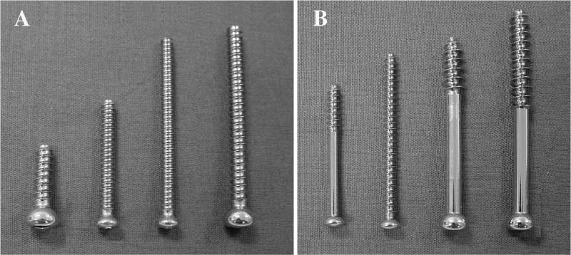
FIGURE 6–3 (A) Cortical vs. (B) cancellous screws.
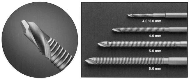
FIGURE 6–4 Self-drilling and self-tapping Schanz screws.
Solid vs. Cannulated Screws
Most bone screws appear to be very similar to metal or wood screws at first glance. They possess a similar thread pattern, size, and overall shape. In addition, these screws usually have a solid core like the conventional screws. Another type of screw often used in fracture fixation is a cannulated screw. A cannulated screw has a hollow core. During surgery pins are initially inserted into bone at the area of the fracture. These pins temporarily represent the axis of the screw. Once the pins are manipulated to the desired configuration and alignment, the cannulated screw simply slides over the pin and is driven into the specimen. This feature provides optimum alignment and is advantageous where precise screw insertion is desired. Both small and large cannulated screws are available. According to Müller et al10 large cannulated screws are commonly utilized in long bone fracture fixation in metaphyseal areas such as the femoral neck, femoral condyles, and tibial plateau. Smaller cannulated screws are typically used in similar regions of smaller long bones such as the distal radius and humerus, as well as the distal and proximal tibia.
Fully Threaded vs. Partially Threaded Screws (Lag Screws)
As in conventional screws, bone screws are offered in both partially and fully threaded versions. Surgeons use fully threaded screws mainly for affixing plates to bone. Partially threaded plates are advantageous when compression between the near and far cortex is desired. The latter have threads only up to a certain point on the shaft. The core is smooth from this point to the head. This allows for the smooth portion of the screw to glide through the near cortex while the threads are driven into the far cortex. This brings the fracture together through compression.
SPECIAL VARIANTS
Special variants include Herbert screws, expansion screws or bolts, dynamic hip screws (DHS), dynamic condylar screws (DCS), and the recently developed cementing screws, interlocking screws, and hollow wall anchor. Correct implementation is achieved through a clear understanding of the advantages and disadvantages of each variant.
Herbert Screws
Herbert screws are unique in that they possess threads of different pitch on each end of the screw.51 The shank of the screw is unthreaded at the center, whereas the ends have threads of different diameters and different pitch. The leading end of the Herbert screw is used for penetration and thus has threads that are small in diameter. The thread at the proximal end of the screw has a smaller pitch than that of the distal end and a larger outer diameter. It is the difference of the thread pitch on the proximal and distal threads that create compression effect to the fractured proximal and distal fragments (Fig. 6–5). Herbert screws were originally designed for scaphoid bone fracture and later were also used for transarticular fractures and many other types of fractures.
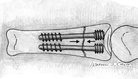
FIGURE 6–5 Herbert screw used for fixation of a phalangeal fracture.
Pedicle Screws
Pedicle screws are used in spinal fixation in conjunction with plates or rods, which will be discussed further below. Most pedicle screws are fully threaded. Although pedicle screws are biomechanically sound, their use is still very controversial, due mainly to the high complication rates. Reported complications include neurological deficits and vascular injuries caused by pedicle violation, epidural hematoma, device breakage, slippage, migration, and malpositioning. These complications can lead to infections, paralysis, and weakness of the lower extremities and bladder and bowel control problems. The solution is 100% accuracy of screw placement without pedicle violation. The newly developed concept of a self-guided pedicle screw (Fig. 6–6), invented by Dr. Baoren Liu and further developed in the authors’ laboratory (see Chapter 35), may bring a bright future to the use of pedicle screws.52
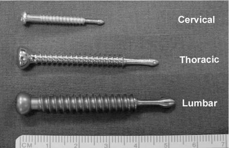
FIGURE 6–6 Liu’s self-guided pedicle screw.
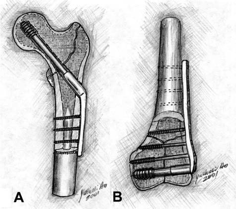
FIGURE 6–7 (A) Synthes’ DHS and (B) DCS for fracture fixation of proximal and distal femoral fractures.
Dynamic Hip Screws/Dynamic Condylar Screws
Dynamic hip screws (DHS) are internal fixation devices used for femoral neck fractures in conjunction with “lateral plates” (Fig. 6–7A). More specifically, DHS are often used in intertrochanteric, subtrochanteric, and basilar neck fractures. These special screws are much more complex than other bone screws. DHS consist of a screw and bone plate assembly. Once proper alignment is obtained using Kirschner wires and angle guides, the canal for the screw is reamed and tapped if necessary. With the canal properly prepared, the DHS is then inserted followed by the chosen DHS plate. The DHS plate is fixed to the femoral surface using the screw of choice, typically cortical screws.
Dynamic condylar screws (DCS) are used for distal femoral fractures (Fig. 6–7B). DCS are structurally similar to DHS. They are comprised of a screw attached to a bone plate. Installation procedures for the DCS are very similar to the DHS. After Kirschner wires are used with an angle plate to achieve optimum alignment, a canal is created with a reamer and tapped if needed. The screw is inserted and a bone plate is attached to both the screw and bone.
Cementing Screws
Cementing screws are an experimental screw design currently being tested in Belgium by Reynders16 (see Chapter 22) and in the United States (at the authors’ laboratory) by McKoy and An15 (see Chapter 21). Cementing screws are unique in that they have through-holes spaced at intervals along the shank. These holes allow injected bone cement to flow through the screw into the surrounding bone, providing a more stable and robust fixation (Fig. 6–8). In the authors’ laboratory, we compared the ultimate holding power of a new cementing screw (8 to 10 holes, evenly spaced) injected with polymethylmethacrylate (PMMA) with a solid screw with the same dimensions secured with PMMA by the standard technique. Both screws were placed into embalmed and fresh-frozen lumbar vertebral bodies and pulled out using an MTS system. The cementing screw had 278% greater holding power compared with the standard screw. The cementing screw provided a dramatic increase in holding power in osteoporotic bone. This novel screw is promising for fixation in osteoporotic bone and warrants clinical evaluation. Dr. Reynders’ screw design has two side holes and has been effectively used clinically for metaphyseal fractures.16
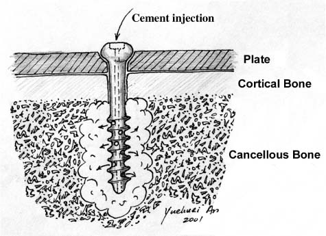
FIGURE 6–8 The mechanism of the McKoy-An cementing screw.
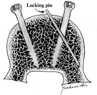
FIGURE 6–9 The mechanism of the McKoy-An inter-locking screw.
Interlocking Screws
An interlocking screw was recently designed in the authors’ laboratory by McKoy and An (see Chapter 20).17 It features the interlocking of the inserted screw by a locking pin (Fig. 6–9). Mechanical testing showed a larger force was required to pull out the interlocking design than the standard screw. The locking screw not only helps to prevent screw backout but also adds additional bony purchase. This new interlocking screw for osteoporotic bone is very promising and warrants clinical evaluation.
Expanding Bolts or Screws
Lesoin et al12 published an early report on the expanding screw or bolt in 1983. It consists of an expanding cylinder and a screw. It was designed for anterior cervical spine fixation. The same principle has been recently adapted for a new design of pedicle screw (Fig. 6–10).14 The advantages of pedicle screw fixation depend on its ability to maintain bony purchase until the fusion mass is stable. The combination of osteoporotic bone with removal and replacement of pedicle screws in revision procedures substantially reduces screw mechanical fixation strength and can lead to clinical failure. The expanding pedicle screw design could be used to improve biomechanical fixation in bone of compromised quality. The mean axial pullout force in bone of all qualities was increased 30% when the expanding pedicle screw design was used.14 This included an appropriate 50% increase in pullout force in bone of poor quality (low bone mineral density). The preliminary clinical and radio-graphic results were supportive of the biomechanical design rationale and mechanical testing.
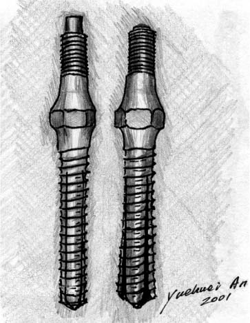
FIGURE 6–10 Omega21™ expandable screw for spine fixation.
Hollow Wall Anchor
A hollow wall anchor recently tested in the authors’ laboratory has shown promise for fixation in osteoporotic bone.20 We compared the ultimate holding power of this expandable anchor (Fig. 6–11) with a standard solid screw of similar dimensions. The solid screw and the expandable anchor were both placed into fresh-frozen lumbar vertebral bodies and pulled out using a mechanical testing system. The expandable anchor had a holding power 74% greater than the standard screw. The expandable anchor provides a significant increase in holding power without the problems associated with cement. This prototype anchor is promising for fixation in osteoporotic bone and warrants further evaluation. A more theoretical and experimental analysis of this technique was reported previously and its performance was significantly better than conventional screws for fixation in osteoporotic bone.53
PLATES
Since the 1960s, both rigid fixation (AO principles) and biological fixation have evolved to provide for improved healing. Even with the widespread use of intramedullary (IM) nailing for diaphyseal bone fractures, plate osteosynthesis is still recognized as the treatment of choice for most articular fractures, many metaphyseal fractures, and certain diaphyseal fractures such as those in the forearm. Importantly, the evolution of internal fixation and specifically the emerging of the concept of biological fixation has been largely due to the development of plating techniques.
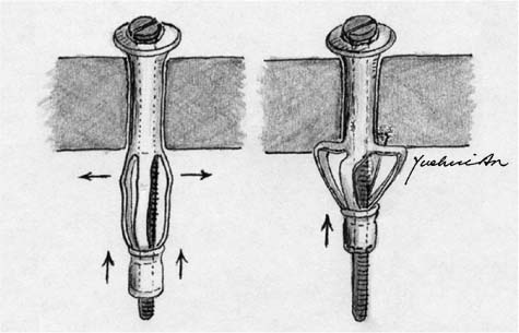
FIGURE 6–11 Expandable hollow wall anchor.
RIGID FIXATION AND BIOLOGICAL FIXATION
AO principles for internal fixation, based on Danis’ work,3 include anatomical reduction, stable fixation, and early limb mobilization.10 The first AO self-compressing plate was reported in 1963 and is still widely used.54 The oval screw holes and eccentrically placed screws provide self-compression to the fractured bone ends. Danis also designed a compression device for applying compression to conventional plates, which is not widely used today.54 The famous dynamic compression plate (DCP) was introduced in 1969 for fracture treatment (Figs. 6–12A,B).55–57 Besides its use for general rigid fracture fixation, it has been also used as a tension band, neutralization, and buttress plate.10,27 A similar design was reported by Mittelmeier in 1974.27,58 Using these rigid fixation techniques, bone healing is normally primary with scarce radiographic callus formation. However, to achieve anatomical reduction and stable fixation, excessive exposure of the fracture site and dissection of the periosteum are needed, which inevitably results in damage to the local blood supply. Another disadvantage of these techniques is the effect of stress protection, which causes local bone necrosis and osteopenia.
Due to the limitations of the early compression plate versions, with resulting damaged blood supply and bone loss adjacent to the plate caused by excessive exposure of the fracture sites and stress shielding (stress protection),59 a new concept of internal fixation evolved nearly 20 years ago that is termed biological fixation.27 Biological fixation can be defined as fixation that limits the injury to soft tissues and blood supply.27
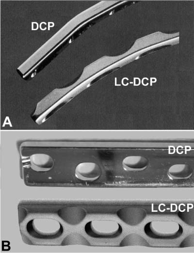
FIGURE 6–12 (A) The standard AO dynamic compression plate (DCP) and (B) the limited contact dynamic compression plate (LC-DCP).
Several plate designs directly and indirectly supported the new concept, such as the wave plate by Brunner and Weber (Fig. 6–13)60 and the bridge plate by Heitemeyer et al.61,62 These plates bypass the fracture site to reduce the vascular disruption and allow easier bone graft at the fracture site. In 1990, Perren et al27,63 published their new plate design for biological fixation, the limited contact dynamic compression plate (LC-DCP) (Figs. 6–12A,B). This design significantly reduces the effect of stress protection of the plate and the disturbance of blood supply, resulting in a lesser degree of local osteoporosis and clinically reduced nonunion and infection rates.
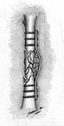
FIGURE 6–13 The wave plate.
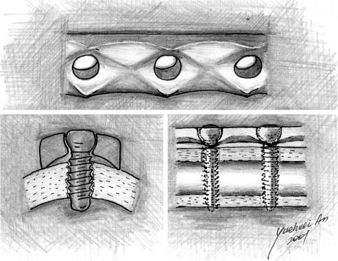
FIGURE 6–14 Point contact fixator (PC-Fix).
For addressing similar circulatory and stress concerns, the point contact fixator (PC-Fix) has recently been introduced (Fig. 6–14).30,31,64,65 In a sheep tibial fracture model, the strength values in the PC-Fix groups at 12 and 96 weeks were significantly higher than in the corresponding DCP groups.65 Healing of simple diaphyseal fractures treated by PC-Fix was superior to that achieved by conventional DCP. The histological evaluation suggested that the observed differences can be accounted for by the absence of implant-related cortical necrosis and by the circumferentially uninterrupted (if smaller) callus in the PCFix group.
Another recent development based on the same principle is a minimum contact plate (MCP) designed by Abel and Sun (Fig. 6–15).29 Four-point bending and torsion tests were conducted to compare the new MCP with the DCP and LC-DCP. Mechanically, the MCP plate was found to have adequate stiffness and strength for clinical application because it is at least as stiff and strong as one of the commonly used plates under both bending and torsional loading conditions.
SPECIAL DESIGNS THAT MAY BE USED FOR OSTEOPOROTIC BONE
Based on their shapes, there are many special designs that fit the needs of osteoporotic bone fixation, including clamp-on plates, blade plates, less invasive stabilization system (LISS) plates, etc.
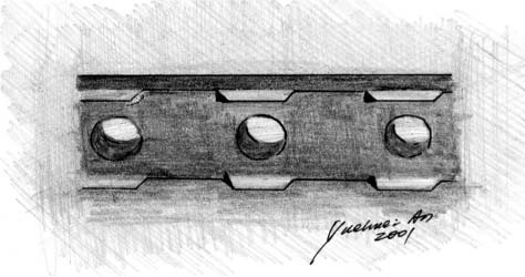
FIGURE 6–15 Minimum contact plate (MCP).
LC-DCP, MCP, and PC-Fix
As mentioned above, LC-DCP, MCP,29 and PC-Fix reduce the contact area between the plate and the adjacent bone surfaces, leading to decreased effect of stress protection and clinically lower rates of delayed union and nonunion. They have great potential for treating osteoporotic fractures.
Adhesive Plate
The design of the adhesive plate was reported by Meyrueis in 1977 but it has not been well used and documented.24,66 The ridges on the undersurface of the plate increase the adherence of the plate to bone (Fig. 6–16). By increasing the coefficient of friction between the plate and the bone, the stresses on the screws can be diminished by one third. The ridges should not be such as to prevent the later removal of the plate. Further work both experimentally and clinically is needed for effective use of this plate design. It should be noted that the PC-DCPs may have similar effect to that offered by the adhesive plate, a factor that also warrants further investigation.66
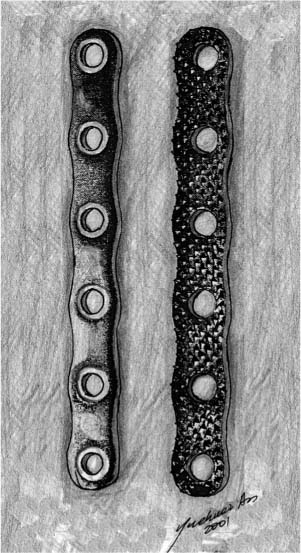
FIGURE 6–16 Meyrueis’ adhesive plate.
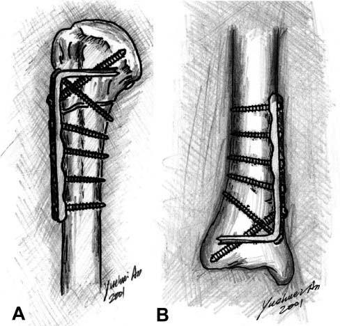
FIGURE 6–17 Blade plates fixed in (A) proximal humerus and (B) distal tibia.
Blade Plate
Blade plates are L-shaped plates consisting of the plate portion and the blade.67,68 They are commercially available (Synthes, USA) and can also be made from a standard bone plate as described by Dr. Palmer in Chapter 24 of this book. The plate portion is fixed to diaphyseal or metaphyseal areas of long bone and the blade is inserted into the end of the bone (epiphyseal or metaphyseal areas, such as humeral head, proximal and distal femoral condyle, upper or distal tibia) (Fig. 6–17). Blade plates offer stable fixation because of the fixed angle at the plate-blade junction.67,68
Buttress Plate
The condylar buttress plate is a broad dynamic compression plate with cloverleaf distal portion for accommodating up to six cancellous screws. It is suitable for fixing comminuted femoral condylar fractures. It does not provide rigid fixation as a DCS or blade plate. Also, the relationship between the screws and the plate is not fixed as in LISS.
Mennen Plate
A paraskeletal clamp-on plate has been developed that maintains the operatively reduced position of a fractured long bone during the healing phase while having a minimal effect on the healing procedure.26,69,70 The plate consists of a central ridge with paired fingerlike projections on each side, constructed in such a manner that in head-on projection the ridge and two projections form just slightly more than a semicircle (Fig. 6–18). The points of the projections, which are wedge-shaped and bent at right angles toward the center, are squeezed into the bone with a crimping tool. The technique is simple, the operating time significantly shortened, and the healing time notably reduced; fracture union is sound without signs of disuse osteopenia, stress protection, or damage to the bony architecture due to drill holes.69,70 The plate has been used for many different kinds of fractures of long bone,69–71 metacarpal bone,72 and even mandibular bone.73,74
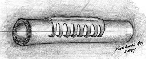
FIGURE 6–18 Mennen plate.
The Mennen plate has been also advocated for femoral shaft and femoral periprosthetic fractures (Figs. 6–19A,B), as well as revision total hip surgery (combined with bone graft) for patients with severe bone loss. Mennen plate fixation provides an adequate and easy technique for femoral periprosthetic fractures and aseptic loosening of total hip replacement with severe bone loss. By preserving the periosteal blood supply, the time required for bone graft incorporation is shortened, resulting in an early final outcome.75–77 However, controversy exists with evidence claiming less adequate fixation of elderly femoral periprosthetic fractures.71,78 Therefore, the safest use of the Mennen plate may be non-weight-bearing tubular bones (Figs. 6–19A,B) and the mandible.
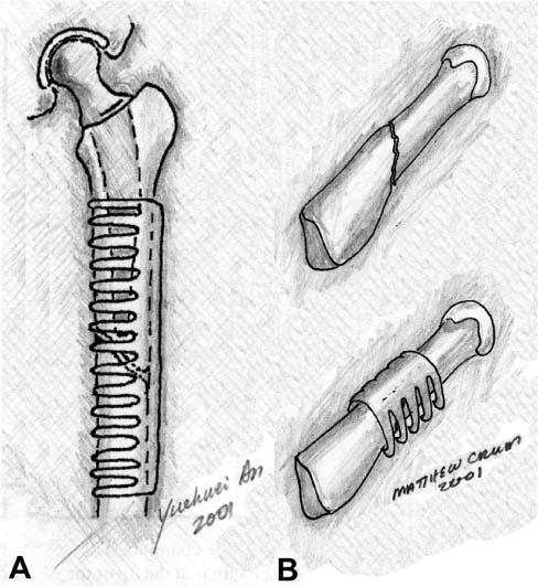
FIGURE 6–19 Mennen plate fixation of (A) a femoral periprosthetic fracture and (B) a metacarpal fracture.
Zespol Plate
Developed by Ramotowski et al32 in Poland, Zespol is a system consisting of a plate, platform screws, and nuts that form a small clamp fixator (Fig. 6–20). In this procedure, the plate is not screwed onto the surface of the bone, but is fixed above the bone by special platform screw bolts. The ZESPOL system has less bending stability than DCP. However, the stability of the Zespol system can be regarded as being sufficient overall. The Zespol fixator can be used either internally or externally. Based on its design, Zespol features fixed-angle, self-compression, less soft tissue injury, and preservation of blood supply (if used externally).
Cushioned Plates
A cushioned plate includes a metal plate portion and a plastic part underneath the metal plate (cushion)79,80 or around screw holes (plastic washers, namely stress-relaxation plate),81 leading to less rigid fixation, although stable fixation is obtained. Less stress protection and resulting osteopenia under the plate is expected for this kind of device, making the fixation more “biological.”
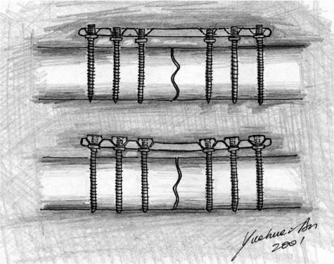
FIGURE 6–20 Zespol plate.
Axially Mobile or Sliding Plates
A reduction in axial stiffness of fixators (or plates) has been shown to be beneficial to bone healing, and many external fixators have been designed that incorporate axial dynamization. Recently two similar axially mobile (sliding) plates have been designed for long-bone fracture fixation, to give the bone fragments a degree of axial mobility while maintaining bending and torsional stability after fixation.82–84 Mechanical testing data have shown that the sliding plates are comparable in both bending and torsion with conventional compression plates. Actually, plates with a sliding feature had been reported early in the history of internal fixation of bone fractures, including the Lambotte plate (1909), Townsend-Gilfillan plate (1943), and Egger plate (1948). Theoretically, if the fixation is stable under bending and torsional loading, axial sliding will mechanically stimulate the fracture site for more “biological” bone healing (secondary callus formation).
Augmentation Methods for Plate Fixation
The Schuhli nut was originally designed for plate fixation in osteoporotic bone.22,85 It elevates the plate above the bone surface (Fig. 6–21), making less direct contact between the plate and bone and resulting in preserved blood supply. The nut can also reduce the mobility of the screw within the screw hole, leading to less motion between the screw and the plate.86 In addition, in the case of missing cortical bone, Schuhli nuts can serve as proximal cortices and make “bicortical fixation” feasible.87
Bioabsorbable strips are another kind of augmentation of screw/plate fixation (see Chapter 23).88 The strip is introduced into the medullary canal through the fracture site. Then, screws penetrate the proximal cortex, the strip, and finally the distal cortex, resulting in a stable “tricortical fixation” of the screw/plate (Fig. 6–22).88
Cement augmentation is a major technique and it will be discussed below in the “Cement and Composite” section.
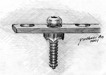
FIGURE 6–21 Schuhli nut.
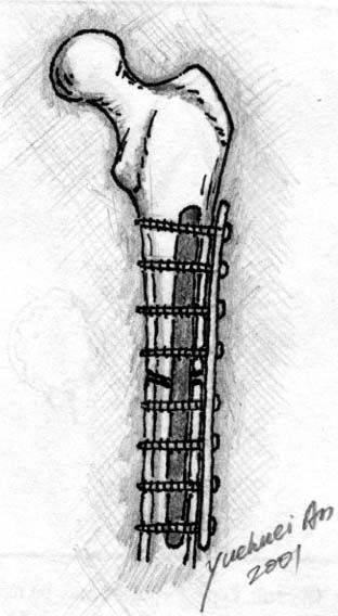
FIGURE 6–22 Augmentation of plate-screw fixation using bioabsorbable strips.
MINIMALLY INVASIVE FIXATION TECHNIQUES
Minimally invasive percutaneous plate osteosynthesis (MIPPO) for distal femoral fractures,89,90 transarticular approach and retrograde plate osteosynthesis (TARPO) for distal femoral fractures,91 LISS,34 minimally invasive surgeries for foot and ankle fractures,92,93 and a recent development of percutaneous compression plating of intertrochanteric hip fractures94 are common types of minimally invasive plate fixation techniques. Here we use LISS as an example (see Chapter 25).
LISS is a recent development for fixation of long bone fractures, and features locked screws and minimally invasive surgical procedures (see Chapter 25). It is an internal fixator with the plate lying beneath the deep fascia and muscle but outside of the periosteum. The plate is anatomically preshaped (Fig. 6–23). The screw used for LISS is monocortical, self-drilling, and self-tapping, and fixes itself to the plate after complete insertion. It preserves blood circulation because the plate is inserted through a small incision at the epiphyseal level and no excessive soft tissue dissection is needed (biological fixation). The beneficial result has been shown in several publications.95,96 The fixation is rigid because there is no movement at the screw-plate junction (fixed-angle concept). Although the product has been on the market for several years, there are only a few basic research and small series in the literature.33,34,97 The LISS is indicated for the stabilization of fractures of the distal femur (distal shaft, supracondylar and intraarticular fractures). Clinical results have shown that LISS is beneficial for osteoporotic bones and periprosthetic fractures.
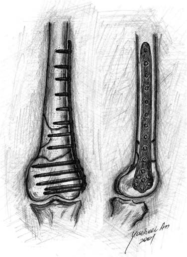
FIGURE 6–23 LISS fixation of comminuted distal femoral fracture.
INTRAMEDULLARY NAILS
The internal fixation of long bone with IM nails has become one of the most frequently performed procedures in orthopaedics today. Although the operation is commonly used to stabilize complicated fractures of both the humerus and tibia, it is in the femur where it has truly proved its worth. With the development of new hardware and the refinement of technique since its introduction in World War II, IM nailing has become the new standard for the treatment of long bone fractures.50
The theory underlying the procedure is simple. Placement of an internal fixation device aids in the transmission of forces from one end of the bone to the other. By allowing the implant to carry the majority of the stress, the damaged bone is better able to maintain alignment as well as lay down a proper matrix. With these two effects, IM nailing lowered the risk of pseudoarthrosis and infection, shortened hospital stay, and accelerated the return to function. Studies show that with femur fractures in trauma victims, early skeletal stabilization substantially reduces the incidence of pulmonary complications, shortens ventilator and intensive care unit times, and improves the overall survival rate.50
The merits of IM nailing are even more important when patients with osteoporosis present with femoral fractures. These patients often have complicated shatter fractures that require rigid stabilization. Nailing is particularly suited to osteoporotic bone because its central location in bone distributes loads more uniformly than do plates. Since the bone is already in a weakened state, this distribution reduces the risk of pseudoarthrosis and secondary stress fractures.47 Elderly patients also benefit from shortened hospital stays, reduced infection rates, and fewer pulmonary complications.
The diaphysis with its large medullary canal of osteoporotic long bone is not always amenable to stabilization with plating because the anchoring screws prefer a thick cortex to maintain purchase. Interlocking IM nailing can bridge the two sides of the cortex of osteoporotic bone to provide rigidity but maintains less stability than in normal bone.98
DEVELOPMENT OF INTRAMEDULLARY NAILING
The modern era of IM fixation is credited to Dr. Kuntscher of Germany.9,10 While he did not originate the concept of IM fixation, he was the first to systematically develop the technique based on basic science and clinical research conducted in the 1940s. Despite Kuntscher’s clinical success, IM nailing did not become a popular procedure until the late 1970s. This was in part due to the 1958 formation of the Swiss AO group and their organized study of methods of internal fixation. They focused their research on the plate and screw techniques and regarded IM nailing as a less rigid and inferior form of fixation. The group ultimately published their results in 1970 as the now-famous “Manual of Internal Fixation.”10 With the advent of improved imaging and cannulated lag screws later in the decade, it became easier to perform IM nailing as a closed procedure. As surgeons saw decreased blood loss and improved infection rates, interest in the procedure surged. At this time, Kuntscher performed a series of closed IM nailings that finally established the technique as the standard of care.99
Related posts:
 External Fixation in Osteoporotic Bone
Norian SRS Resorbable Cement for Augmentation of Internal Fixation of Hip Fractures
Synthes Spiral Blade Intramedullary Nail System for Proximal Humeral Fractures
An Injectable Cementing Screw for Fixation in Osteoporotic Bone
Internal Fixation of Osteoporotic Proximal Femoral Fractures Using a Novel Device Enhanced by Hydroxyapatite Granules
TPS Devices for Treatment of Vertebral Tumors and Pathological Compression Fractures
External Fixation in Osteoporotic Bone
Norian SRS Resorbable Cement for Augmentation of Internal Fixation of Hip Fractures
Synthes Spiral Blade Intramedullary Nail System for Proximal Humeral Fractures
An Injectable Cementing Screw for Fixation in Osteoporotic Bone
Internal Fixation of Osteoporotic Proximal Femoral Fractures Using a Novel Device Enhanced by Hydroxyapatite Granules
TPS Devices for Treatment of Vertebral Tumors and Pathological Compression Fractures
Stay updated, free articles. Join our Telegram channel

Full access? Get Clinical Tree


