Fig. 1
The three rotations necessary to describe full 3D orientation. The IMU outputs the rotation around the Earth-fixed reference coordinate system’s x-, y- and z-axis
The fusion of the data from all internal sensors is usually performed using a Kalman filter [21]. A Kalman filter is a set of equations which try to estimate the state of a discrete-time controlled process. In a recursive matter, it estimates the states in the past, present and in the future, even when the precise nature of the modeled system is unknown [22]. The estimated state at some point in time is adjusted by feedback in the form of potentially noisy measurements from the sensors. This way, a continuous cycle is achieved by first projecting into the future and then improving the value based on actual measurements. The forward projection is based on past values which means that in order for the IMU to produce reliable output, it is necessary for the Kalman filter to build up a history first [23]. This initial warm-up time depends on the environment where the sensor works in.
Behrens et al. [16] proposed an inertial sensor-based guided navigation tool for tumor re-identification. They make use of the fact that in cytoscopic interventions the anatomy of the bladder reduces the degrees of freedom (the bladder opening with the urethra forms a fixed pivotal point). The endoscope movement they try to estimate is therefore limited to a vertical, horizontal and axial rotation as well as translation. Integrating one sensor into endoscopes with different view angles and applying an extended endoscope model they are able to accurately measure orientation angles but experience inaccuracies trying to measure the translation of the endoscope due to temporal drift effects that occur due to double integration of the accelerometer values.
Ren et al. [19] developed a prototype IMU including an extended Kalman filter for tracking hand-held surgical instruments and compared it to optical tracking. In their work, they considered the problem of estimating the gravity and magnetic field under small perturbations and their relationship to the measurements of the gyroscope sensors. They were able to achieve very accurate results, however, they experienced problems with environmental interference and their gyro-assisted compensation was not able to fully compensate for it.
O’Donovan et al. [17] used an inertial and magnetic sensor-based technique for joint angle measurements. The technique makes use of a combination of IMUs attached to the lower extremities to compute joint angles and the ankle joint. Since the IMUs are not depending on a fixed reference coordinate system, their technique may be suitable for use in a dynamic system such as a moving vehicle.
All these systems report problems estimating the heading information from the IMU due to magnetic field distortions. The rotation around the z-axis (heading information) is heavily relying on accurate magnetic field measurements. If the surrounding magnetic field is distorted, the employed Kalman filter relies more on the measurements from the gyroscope and accelerometer, introducing drift errors due to the above mentioned double integration.
Hybrid systems were proposed to overcome the limitations of a single tracking technology [13, 24–26]. Haid et al. [13] presented novel methods combining image processing routines with inertial sensors for surgical navigation and Ren et al. [27] proposed an integrated tracking system for endoscopic surgery combining inertial sensors with electromagnetic tracking to reduce the effect of environmental distortions. However, these systems have an increased complexity and are significantly more expensive.
In this book chapter, we propose a low-cost system to measure the acetabular fragment orientation during PAO surgery which is solely based on inertial measurements units Fig. 2. We make use of a newly designed device to measure the orientation of the patient’s anterior pelvic plane (APP) and to register the orientation of the patient’s pelvis and acetabular fragment, respectively, we are able to compute the inclination and anteversion of the acetabular fragment intra-operatively in real-time. Compared to work reported in [16], we only measure rotations and combine readings from two IMUs. Walti et al. [28] use an inertial measurement sensor to track the surgical instrument during pedicle screw placement. Their application makes use of just one sensor and the whole procedure to place the pedicle screw only takes a short amount of time reducing the influence of drift errors. Our work can be compared to [17] with the difference that we use the system in a clinical setting inside the operating room (OR) for a demanding open surgery. To our knowledge, we are the first to use the IMUs to measure the acetabular orientation during PAO surgery, successfully removing the line-of-sight limitation of optical tracking systems.
Fig. 2
Our application to visualize the re-orientation of the acetabular fragment. The four landmarks can easily be picked on the computer model. Battery level and signal strength of the sensors is indicated using green (or red) marks at the top. The updated inclination and anteversion values are shown on the side below the starting values. The acetabular fragment is rotated on the screen to give the surgeon a 3D view of the current state (Color figure online)
2 Materials and Methods
2.1 Pre-operatively
For visualization purposes a patient-specific computer model which is acquired from segmented CT data is used. Next, four landmarks are picked on the computer model before the surgery. These landmarks—left and right anterior superior iliac spine (ASIS) as well as the left and right pubic tubercles (PUBIS)—define the APP. Reorientation of the acetabular fragment is modeled as a rotation of the fragment around the center of the femoral head. With the help of a previously developed comprehensive PAO planning system [9] we estimate the femoral head center by fitting a sphere to the femoral head. Additionally, to compute the acetabular orientation (anteversion and inclination) the acetabular cup plane normal has to be known. To compute the cup plane, the acetabular rim points are automatically detected using the PAO planning software and a plane is linearly fitted through the points to get the plane normal [9].
2.2 Inertial Measurement Units
Two commercially available MEMS inertial sensors (Xsens Technologies, The Netherlands) fuse data from three internal accelerometers, three gyroscopes and three magnetometers as well as a barometer to output full 3D orientation data in an Earth-fixed coordinate system. The sensor fusion is performed using a variation of the Kalman filter [21]. The orientation data is read into our application and processed using the software development kit provided with the sensors. As the sensor system used in this work is a commercially available system and therefore not open, we refer the reader to other works using Kalman filter equations and IMUs for more on this topic [29, 30]. It is possible to read the orientation from the sensor in three different representations (Euler angles, rotation matrix and quaternion) which are all equal and represent the same orientation in the Earth-fixed coordinate system. We did internal processing using the quaternion representation, however, in this book chapter, for the sake of simplicity, we use rotation matrices to explain all the computations performed.
2.3 Registration
After acquiring all pre-operative information, the computer model’s orientation is registered to the patient’s pelvis’ orientation. For that task, we designed a new device which aligns a single IMU with the patient’s APP (Figs. 3 and 4). Aligned with the device’s top plate, the sensor’s orientation (local z-axis) represents the APP normal since all three pillars are of equal length and parallel to each other. The computer model is then transformed in a way that its APP (known from the picked landmarks), and therefore the whole model, has the same orientation as the patient’s APP/pelvis. One hundred data packets from the wireless sensor (quaternion orientations) are recorded and the orientation of the APP is estimated by taking the mean of all quaternion orientations to filter out noisy data. The algorithm proposed by Markely et al. [31] is used to compute the average quaternion by performing an eigenvalue/eigenvector decomposition of a matrix composed of the given quaternions.
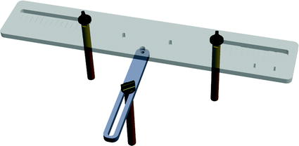
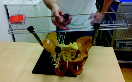
Fig. 3
APP measuring device. Three pillars are placed on the right and left anterior superior iliac spine (ASIS) and one of the two pubic tubercles. The sensor is placed on the top plate which is aligned with the APP
Fig. 4
The newly designed APP measuring device is placed on the patient’s pelvis so that the three levers are placed on the two ASIS and one pubic tubercle. The top plate will then be aligned with the APP and the sensor can measure its orientation
2.4 Sensor Setup
After registration, the two sensors are mounted to the patient: one sensor is attached to the patient’s pelvis (Sensor A) and the other is mounted to the acetabular fragment (Sensor B, see Fig. 5). The output from Sensor A and B at time t, represented using a rotation matrix, specifying the orientation of a sensor with respect to an Earth-fixed reference orientation O is then:

With  and
and  being the rotation matrices of sensor A (pelvis) and B (fragment) at time t representing the rotations necessary to bring sensor A and B from the reference orientation O (perfectly aligned with the Earth-fixed coordinate system) to its current orientation. The rotation is expressed as rotations around the three axes of the Earth fixed coordinate system (roll—x-axis, pitch—y-axis, yaw—z-axis). Before reorientation, the starting orientation of each sensor is recorded (t = 0). At every time point t after the initialization step (t = 0), we take the current rotation matrices from sensor A and B to compute the incremental update between t − 1 and t for each sensor:
Intuitively speaking,  and
and  define a rotation from the sensor’s orientation at time point t − 1 back to the reference orientation O and then forward to the orientation at time t.
(1)
(2)
and being the rotation matrices of sensor A (pelvis) and B (fragment) at time t representing the rotations necessary to bring sensor A and B from the reference orientation O (perfectly aligned with the Earth-fixed coordinate system) to its current orientation. The rotation is expressed as rotations around the three axes of the Earth fixed coordinate system (roll—x-axis, pitch—y-axis, yaw—z-axis). Before reorientation, the starting orientation of each sensor is recorded (t = 0). At every time point t after the initialization step (t = 0), we take the current rotation matrices from sensor A and B to compute the incremental update between t − 1 and t for each sensor:(3)
(4)
and define a rotation from the sensor’s orientation at time point t − 1 back to the reference orientation O and then forward to the orientation at time t.To estimate the rotation of the fragment with respect to the patient’s pelvis we must account for movements of the pelvis during surgery. The rotation of the pelvis (sensor A) is the same as an inverse rotation of the fragment (sensor B) and vice versa. This way, movements of the patient intra-operatively can be compensated by treating the incremental update of the pelvis  inversely, with the assumption that the rotation center is the same. Therefore, to compute the incremental update of the fragment, we first rotate the fragment by the incremental update from sensor B and then apply an inverse rotation using the incremental update from sensor A:
Using  , we rotate the acetabular cup plane normal at every time point t and recompute the acetabular orientation as described below.
inversely, with the assumption that the rotation center is the same. Therefore, to compute the incremental update of the fragment, we first rotate the fragment by the incremental update from sensor B and then apply an inverse rotation using the incremental update from sensor A:(5)
, we rotate the acetabular cup plane normal at every time point t and recompute the acetabular orientation as described below.2.5 Acetabular Orientation
In our application we compute radiographic inclination and anteversion angles [32] which are defined as:
 of Implant Osseointegration by Means of a Reconstruction Algorithm on Micro-computed Tomography Images
Fusion for Computer-Assisted Bone Tumor Surgery
Three-Dimensional Imaging in Fracture Treatment with a Mobile C-Arm
Assisted Diagnosis and Treatment Planning of Femoroacetabular Impingement (FAI)
Robotics for Musculoskeletal Surgery
of the Art of Ultrasound-Based Registration in Computer Assisted Orthopedic Interventions
of Implant Osseointegration by Means of a Reconstruction Algorithm on Micro-computed Tomography Images
Fusion for Computer-Assisted Bone Tumor Surgery
Three-Dimensional Imaging in Fracture Treatment with a Mobile C-Arm
Assisted Diagnosis and Treatment Planning of Femoroacetabular Impingement (FAI)
Robotics for Musculoskeletal Surgery
of the Art of Ultrasound-Based Registration in Computer Assisted Orthopedic Interventions


(6)
Related posts:
of Implant Osseointegration by Means of a Reconstruction Algorithm on Micro-computed Tomography Images
Fusion for Computer-Assisted Bone Tumor Surgery
Three-Dimensional Imaging in Fracture Treatment with a Mobile C-Arm
Assisted Diagnosis and Treatment Planning of Femoroacetabular Impingement (FAI)
Robotics for Musculoskeletal Surgery
of the Art of Ultrasound-Based Registration in Computer Assisted Orthopedic Interventions
Stay updated, free articles. Join our Telegram channel
Full access? Get Clinical Tree
