Fig. 1
The different pathomorphologies and pathobiomechanics of intraarticular FAI are shown. Top Normal hip with sufficient clearance for range of motion. Bottom left Pincer impingement: early contact of the femoral head and the acetabular rim caused by the excessive acetabular coverage or abnormal orientation of the acetabulum. Bottom right Cam impingement: the femoral head-neck asphericity is jammed into the acetabulum leading to labral as well as chondral damage of the acetabulum and femoral head. The majority of FAI hips exhibit features ofa combined cam-pincer pathomorphology
The diagnosis of FAI is based on clinical examination and imaging modalities such as conventional radiography, MR-arthrography, and computed tomography. Conventional radiography has the advantage of almost unlimited availability, cost effectiveness, and low radiation. Many conventional radiographic parameters have been established that allow the assessment and characterization of morphological parameters of the hip, both normal and abnormal, in patients with FAI (Table 1) [9]. However, conventional radiography allows only static evaluation of the underlying pathology. In addition, it is a two-dimensional representation of a three-dimensional structure, and relies on correct positioning during image acquisition. To counteract malpositioning and subsequent malorientation of the pelvis on the x-ray, software packages have been developed which correct pelvic tilt and rotation after the radiograph has been performed [10, 11]. MR-arthrograms are used for the three-dimensional assessment of bone, as well as periarticular soft tissue such as cartilage, the acetabular labrum, the hip capsule, and the surrounding muscular envelope [12–14]. Similar to conventional radiography, MR-arthrography provides only static impressions of the articulation, while it fails in the assessment of the underlying dynamic problem in FAI. Novel computer-assisted image-guiding software tools have therefore been developed to face this problem [15, 16]. CT is the method of choice for three-dimensional bony reconstruction and dynamic assessment of the hip joint due to its superior contrast properties compared to MRI [17]. The computer-assisted assessment of the dynamic conflict involved in FAI allows simulated range of motion, collision detection and accurate mapping of impingement areas. In addition, treatment planning can be achieved by performing a virtual resection of the previously detected impingement zones at the femoral head-neck junction. This book chapter gives an overview on selected computer-assisted two- and three-dimensional tools and their role for the diagnosis and treatment plan in patients with FAI. The possibility for both static and dynamic evaluation, method reliability and reproducibility, and the applicability in the routine clinical setting are outlined.
Table 1
Definition of the investigated radiographic hip parameters
Parameter | Definition | Normal values [46] |
|---|---|---|
Lateral center-edge angle (LCE) [27] | Angle formed by a line parallel to the longitudinal pelvic axis and a line connecting the center of the femoral head with the lateral edge of the acetabulum | 23°–33° |
Anterior center-edge angle (ACE) [24] | Angle formed by a vertical line and a line connecting the center of the femoral head and the anterior edge of the acetabular rim at 25° to the sagittal plane | >25° |
Acetabular index [28] | Angle formed by a horizontal line and a line through the most medial point of the sclerotic zone of the acetabular roof and the edge of the acetabulum | 3°–13° |
Extrusion index [14] | Percentage of uncovered femoral head in comparison to the total horizontal head diameter | 70–100 % |
ACM angle [23] | Angle constructed by the following points: (A) lateral edge of acetabulum, (M) midpoint of a line connecting the lateral and the inferior acetabular edge, (C) point of the bony acetabulum intersecting the perpendicular line relative to line through point M | 40°–50° |
Anterior coverage [11] | The percentage of femoral head covered by the anterior acetabular rim in AP direction | 15–26 % |
Posterior coverage [11] | The percentage of femoral head covered by the posterior acetabular rim in AP direction | 36–47 % |
Craniocaudal coverage [11] | The percentage of femoral head covered by the acetabular rim in craniocaudal direction | 70–83 % |
Crossover sign [3] | Positive if the projected anterior wall crosses the posterior wall | Negative |
Retroversion index [11] | Ratio of length of retroverted acetabular opening to the entire length of the acetabular opening | |
Posterior wall sign [3] | Positive if the posterior acetabular rim is projected medial of the center of the hip | Negative |
2 Two-Dimensional Computer-Assisted Tools
Evaluation of acetabular pathomorphology for pincer-type impingement (i.e. acetabular overcoverage either from retroversion or protrusion) is routinely performed using conventional two-dimensional radiographs such as an AP pelvis view. However, many radiographic parameters used to assess acetabular orientation and depth are highly dependent on the positioning of the patient during image acquisition [9, 18, 19]. Although AP pelvic radiographs are usually obtained according to a standardized protocol [14], variations of pelvic orientation are a natural consequence of the patient’s posture, body habitus, and level of discomfort with certain positions. These variations are difficult to accurately assess and correct while the image is being acquired without adding additional radiation burden to the patient. If pelvic tilt and rotation are not accounted for during analysis, this can subsequently lead to misinterpretation of radiographic parameters of the hip and, ultimately, incorrect treatment decisions. Variations of pelvic tilt and rotation have been identified as the most important factors influencing the interpretation of radiographic hip parameters [18, 19]. In this context, a recent study evaluated the effect of pelvic rotation and tilt on 11 common radiographic hip parameters (Table 2) [9]. The study investigated potential deviations in an experimental setting involving 20 cadaver pelves. The pelves were placed in a neutral position (neutral rotation and 60° pelvic inclination [20]) prior to acquisition of a standardized AP radiograph. The radiograph was then virtually rotated and tilted in predefined increments. The authors found that five of the eleven parameters (anterior acetabular coverage, posterior acetabular coverage, cross-over sign, retroversion index, and posterior wall sign) changed with increasing pelvic malorientation while the other six evaluated parameters (lateral center-edge angle, acetabular index, extrusion index, ACM angle, Sharp angle, and craniocaudal coverage) exhibited no significant changes indicating to be inert to pelvic malorientation (Table 2).
Table 2
Table outlining the parameters that are inert to pelvic rotation and tilt (restricted to a range of ±24° tilt and ±12° rotation, maximum deviation) [9]
Radiographic hip parameters that are inert to pelvic rotation and tilt | Radiographic hip parameters that change relevantly with pelvic rotation and tilt |
|---|---|
Lateral center-edge angle [27] | Anterior acetabular coverage [11] |
Acetabular index [28] | Posterior acetabular coverage [11] |
Extrusion index [14] | Crossover sign [3] |
ACM angle [23] | Retroversion index [18] |
Sharp angle [47] | Posterior wall sign [3] |
Craniocaudal coverage [46] |
The need to correct for pelvic tilt and rotation lead to the development of a software package called Hip2Norm [10]. Similar to computed tomography, Hip2Norm allows to accurately calculate femoral head coverage from a conventional antero-superior radiograph of the pelvis. The program extrapolates three-dimensional information about the hip joint morphology from two-dimensional AP pelvis radiographs. This is achieved by interactively digitizing the following landmarks from two-dimensional radiographic images: the inferior margins of the tear drops as the horizontal reference, the contour of the projected anterior and posterior acetabular rim, the middle of the sacrococcygeal joint and the upper border of the symphysis as the vertical reference (Fig. 2). Additionally, the femoral head as well as acetabular center and radius are obtained from a fitting circle that is created from three points drawn by the user. The projected anterior and posterior acetabular rims are also manually defined by the user (Fig. 2). The technique is based on a cone-beam projection model presuming the source to film distance, that is extracted directly from the technical documentation of the X-ray machine (Fig. 3), and the object to film distance (representing the surrounding soft tissue envelope) that has previously been shown to be 30 mm on average [19]. The software also requires sphericity of both the acetabulum and the femoral head. The reconstructed coordinate system from the defined landmarks allows for calibrating the acetabular rim back to a neutral, pelvic orientation consisting of pelvic tilt (around the transverse axis), pelvic rotation (around the longitudinal axis), and pelvic obliquity (around the sagittal axis). The latter is corrected by the inter-teardrop line. Pelvic rotation is restored accurately by adjusting the midpoint of the sacroiliac joint and the upper border of the symphysis to meet on a vertical line [10]. Pelvic tilt is corrected with a one-time strong lateral pelvic radiograph and the pelvic inclination angle. The pelvic inclination angle is defined by the intersection of a line connecting the anterior boarder of the sacral promontory with the upper border of the symphysis and a horizontal line (Fig. 4). Normal pelvic inclination has been found to be 60° [20–22]. Pelvic inclination strongly correlates with the change of the distance between the upper border of the symphysis and the midpoint of the sacrococcygeal joint. Thus, one time calibration of the distance with a lateral pelvic radiograph is recommended. However, as a strong lateral pelvic view is rarely obtained in the routine clinical setup, the individual pelvic tilt can be estimated with the vertical distance between the sacrococcygeal joint and the upper border of the symphysis. The mean values for this vertical distance in a normal population have been shown to be 32 mm in men and 47 mm in women [18]. After virtual neutralization of pelvic tilt and rotation, Hip2Norm calculates the corrected coverage of the femoral head (total anterior coverage, total posterior coverage, total cranio-caudal coverage), as well as acetabular version (cross-over sign, retroversion index, posterior wall sign) and further common hip parameters (lateral center edge angle, acetabular index, ACM-angle, extrusion index, anterior center edge angle; Table 1) in this neutralized orientation (Fig. 5) [3, 18, 23–27]. Hip2Norm has been validated and showed high consistency, accuracy, reliability and reproducibility [11]. The mean accuracy to correct for pelvic malpositioning ranged from 0.1° to 0.7° for the angular measurements and from 0.4 to 2.0 % for the relative units/acetabular coverage when compared to the gold standard (defined by computed tomography and conventional radiographs of cadaver pelves in a neutral orientation [11]). The least accurate measurements were found for the lateral center edge angle (ICC 0.53 [0.34–0.77]) [27], the acetabular index (intraclass correlation coefficient [ICC] 0.49 [0.29–0.67]) [28], and anterior center edge angle (ICC 0.54 [0.40–0.81]) [24]. Consistency of the software was assessed by re-transforming radiographic hip parameters obtained from radiographs with the pelvis in predefined malrotation and -tilt back to the neutral orientation (correction algorithm). All parameters showed good to excellent consistency (ICC > 0.6) except the anterior center edge angle (ICC 0.61 [0.29–0.91]). A good to very good reproducibility and reliability (ICC > 0.6) was found for all parameters except for the reliability of the retroversion index (ICC 0.56 [0.46–0.65]) [11].
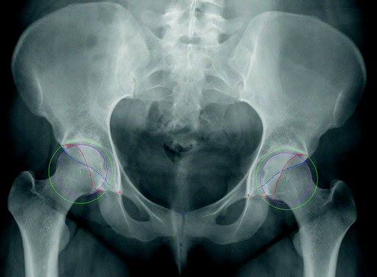
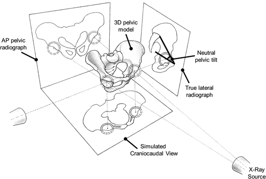
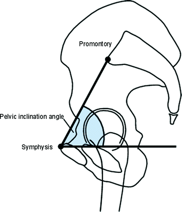
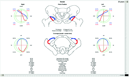
Fig. 2
The graphical user interface of Hip2Norm is shown. For the calculation of radiographic hip parameters (Table 1) and the correction of deviations of pelvic tilt and rotation, the following landmarks are manually plotted [1]. The mid-point of the sacrococcygeal joint (upper blue cross), the upper border of the symphysis (lower blue cross), the inferior margins of the teardrops (red crosses) and the contours of the projected anterior (blue line) and posterior (red line) acetabular rim. Additionally, the femoral head center (pink cross) and the femoral head circumference (pink circle) and the acetabular center (green cross) and acetabular circumference (green circle) are obtained by fitting a circle to three points specified by the user (Color figure online)
Fig. 3
Hip2Norm calculates the three-dimensional configuration of the hip joint from a conventional AP pelvic radiograph. The software uses a cone projection model allowing to determine cranio-caudal, anterior and posterior femoral coverage. In addition, alterations of pelvic tilt, rotation and obliquity can be corrected with the help of vertical/horizontal distances between the symphysis and the sacrococcygeal joint (pelvic tilt and rotation) and the inter-teardrop line (pelvic obliquity). In order to assess pelvic tilt, an additional one-time strong lateral radiograph is necessary to normalize the absolute horizontal distance to the pelvic inclination angle. Alternatively, the individual pelvic tilt can be estimated with mean values for this vertical distance in a normal population (32 mm male; 47 mm female) [11, 18]
Fig. 4
The image shows a schematic of strong lateral pelvic radiograph (superimposition of both femoral heads). Pelvic inclination is measured as the angle between a line connecting the sacral promontory and the anterior boarder of the symphysis and a horizontal line. Normal pelvic inclination has been found to be 60° [20–22]
Fig. 5
The result sheet of the Hip2Norm analysis is shown. After definition of the osseous landmarks (Fig. 3), the software computes common radiographic hip parameters (Table 1). After deviations of pelvic tilt and rotation have been normalized, the software corrects all parameters that show variations depending on pelvic orientation (Table 2) [9]. High software accuracy, consistency and reliability has previously been proven in a validation study [11]
3 Three-Dimensional Computer-Assisted Tools
While conventional imaging modalities provide only static impressions of the dynamic problem in FAI, the data sets of tomographic imaging methods using image guided applications bear high potential for the dynamic assessment of FAI allowing to perform preoperative simulation of range of motion, collision detection and accurate visualization of impingement areas. In this respect, the software HipMotion has been developed to perform a CT based, three-dimensional kinematics analysis of the hip joint. The application uses three-dimensional models of the patient’s anatomy based on polygonal meshes that are created from DICOM (digital imaging and communications in medicine) volume data. CT data originate from a native computed tomography scan without contrast with a minimum slice thickness of 2 mm. The CT scan of the pelvis has to include the proximal femur including the greater and lesser trochanter and distal femur exposing the femoral condyles. Although there is a potential hazard of radiation exposure, the advantages of CT data for three-dimensional model segmentation outweigh those of magnetic resonance imaging. This is mainly due to the sharp contrast between osseous structures and soft tissue. The attempts to use alternative tomographic modalities without radiation such as MRI have been unsatisfactory until now because automated segmentation of three-dimensional models remains a challenge as a result of the morphological complexity and large signal-to-noise ratio of MRI.
3.1 Simulation of Natural Motion Pattern in a Three-Dimensional Model
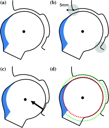
After reconstruction of the three-dimensional polygon model, the femur is separated from the pelvis by manually tracing the joint line. Automatic separation of the two bones is not always feasible due to the proximity of the femoral head and pelvis in the articulation. For simulation of hip joint range of motion and collision detection, realistic, natural implementation of the biomechanics of hip joint motion using a mathematical algorithm is crucial. The first described applications reduced the biomechanical behavior of the hip to a simple ball and socket model with a fixed hip joint center [29]. However, this mathematically feasible method simplifies the calculation while it does not represent the natural motion pattern of a hip joint. In a previous study, it was shown that the hip joint performs a combination of rotation and translation during hip motion [30]. This is, on the one hand, the result from a conchoid shape of the femoral head, and, on the other hand, due to a certain degree of viscoelasticity of the femoral head surface resulting from compressive forces towards the cartilaginous surface within the articulation during hip motion [31]. A modification to the simple “fixed center” algorithm is the constrained method that evaluates impingement areas within a maximum perimeter of 5 mm from the acetabular rim [32]. However, with this method intraarticular impingement is neglected. Another algorithm, the translated method, computes a displacement vector according to the detected impingement and performs an additional translation to the rotational center perpendicular to the detected intraarticular impingement zone. In order to achieve higher accuracy and reliability for the location and extent of osseous impingement areas, the equidistant method has been introduced [15]. This algorithm preserves a constant joint space imitating the cartilage lining at any functional hip position. This is achieved by superimposing the acetabular and femoral sphere center based on the individual joint anatomy. The result is a dynamic joint center during virtual hip motion allowing combined rotational and translational motion patterns (Fig. 6). In an in vitro study, the equidistant method has been proven to be superior to the conventional methods in terms of accuracy and reliability representing the highest resemblance with the natural characteristics of the hip joint (Fig. 7). Thus, HipMotion operates with the equidistant method for simulation of hip motion, collision detection and treatment planning.
 of Implant Osseointegration by Means of a Reconstruction Algorithm on Micro-computed Tomography Images
Fusion for Computer-Assisted Bone Tumor Surgery
Three-Dimensional Imaging in Fracture Treatment with a Mobile C-Arm
Robotics for Musculoskeletal Surgery
of the Art of Ultrasound-Based Registration in Computer Assisted Orthopedic Interventions
Reconstruction-Based Planning of Total Hip Arthroplasty
of Implant Osseointegration by Means of a Reconstruction Algorithm on Micro-computed Tomography Images
Fusion for Computer-Assisted Bone Tumor Surgery
Three-Dimensional Imaging in Fracture Treatment with a Mobile C-Arm
Robotics for Musculoskeletal Surgery
of the Art of Ultrasound-Based Registration in Computer Assisted Orthopedic Interventions
Reconstruction-Based Planning of Total Hip Arthroplasty


Related posts:
of Implant Osseointegration by Means of a Reconstruction Algorithm on Micro-computed Tomography Images
Fusion for Computer-Assisted Bone Tumor Surgery
Three-Dimensional Imaging in Fracture Treatment with a Mobile C-Arm
Robotics for Musculoskeletal Surgery
of the Art of Ultrasound-Based Registration in Computer Assisted Orthopedic Interventions
Reconstruction-Based Planning of Total Hip Arthroplasty
Stay updated, free articles. Join our Telegram channel
Full access? Get Clinical Tree
