Computer Navigation in Hip Arthroplasty and Hip Resurfacing
Rupesh Tarwala and Lawrence D. Dorr
Key Points
• Successful total hip arthroplasty (THA) depends on proper positioning of components.
• Computer navigation helps in accurate cup position and reduces chances of human error.
• Navigation is a very useful tool in avoiding malposition of the cup in minimal incision surgery.
• Restoration of leg length and offset is most accurate with navigation.
Rationale and Indications
Since Smith-Petersen designed a successful hip arthroplasty operation in the 1930s, hip surgery has been the glory operation for orthopedics. Each decade has brought improvement. Austin-Moore replaced the femoral head with a monoblock stemmed prosthesis in the 1940s. The 1950s saw metal-on-metal articulations for the first time. The revolution occurred in the 1960s, when Charnley used acrylic cement to fix the acetabular and femoral components, which resulted in much greater patient satisfaction than the press-fit stems with monoblock heads of the 40s and 50s. Charnley’s results with all-polyethylene cups bettered those achieved with McKee-Farrar metal-on-metal designs, so the Charnley hip replacement became the gold standard around the world.
Innovation did not stop with Charnley. Charles Engh led the move to bone ingrowth fixation with the anatomic medullary locking (AML) design in the late 1970s. The 1980s saw an explosion of implant designs and companies. Total hip replacement and, subsequently, total knee replacement made orthopedics a commercial bonanza, and every new small company had its own implants. The advantage for surgeons was that the best designs were soon revealed, and bone ingrowth fixation gradually became dominant. The focus in the decade of the 1990s was the articulation surface, and metal-on-metal, ceramic-on-ceramic, and highly crossed linked polyethylene significantly increased the longevity of operations. By the decade of the 2000s, fixation was a certainty with confidence in the durability of the articulation.
Failures in the decade of the 2000s can be attributed to failure of performance of the operation by the surgeon. Surgeons operate using their experience, instinct, and intuition to create a result. This is effective for most patients. However, all surgeons have outliers, and with hip replacement, these outliers occur when the surgeon does not implant the components in the correct position. The version of both the femoral component1–3 and the acetabular component4–7 is misjudged, even by experienced surgeons.
With predictability of fixation and articulation surfaces, it is incumbent on arthroplasty surgeons to make the predictability of component position secure. The only method to do this requires the use of machines in the operating room to overcome human errors of judgment. Judgment errors are most common with the acetabulum because it is attached to the pelvis, which is further influenced by the spine and the longitudinal axis of the body. The surgeon’s judgment of cup position is confounded by the pelvis being buried under skin, fat, and muscle. Estimation of pelvic position is worse when the operation is performed in the lateral position because pelvic landmarks are more hidden than when the supine position is used.
Femoral component anteversion can be estimated by the surgeon more easily than acetabular position because more bony landmarks are evident. The femoral neck proximally can be sighted, as can the epicondyles distally, to judge the axis of the femur. With cemented stems, because the stem is smaller than the canal and can be manipulated inside the canal, the anteversion can be more precisely controlled by the surgeon. Errors are still made, as was evidenced in two reports.1,3 Surgeons have much less control with cementless stems, which are rigidly press-fit in a fixed bony structure. The bony structure itself varies from retroversion to high degrees of anteversion.8 Insertion of a stem is controlled by femoral bony neck anteversion, the anterior-posterior isthmus at the level of the lesser trochanter, and diaphyseal bone by both external radius and internal thickness of the posterior cortex (type A, B, C bone9). In fact, estimates by the same experienced surgeon have the same precision for stem anteversion (11.3 degrees)2 and cup anteversion (12.3 degrees).4 This precision means that the estimate can be wrong by these many degrees. By contrast, the precision of computer navigation in the same studies was less than 5 degrees for both stem and cup. For surface replacement, computer navigation is used to center the stem and cup; this nearly eliminates the risk of neck notching.
Whether the arthroplasty is conventional or surface, the principles of cup position are the same. The most important technical factor in cup position is COR, which should be within 2 mm of anatomic for greatest durability of the arthroplasty.10 The COR has the most influence on impingement: if it is lateralized, the metal neck can impact the edge of the metal shell (risk increases with poor combined anteversion); if it is superior or medialized, the risk of bone-on-bone impingement increases unless femoral offset, or hip length, is increased (by the use of an offset stem or by lengthening of the hip/leg).
Inclination and anteversion of the cup also have rigid criteria for success. Inclination cannot exceed 45 degrees for optimal wear11; when it exceeds 50 degrees, it causes runaway wear with metal-on-metal12,13 and increases the risk of breakage of ceramic14 or highly cross-linked polyethylene.15 Cup anteversion can be targeted to a mean of 20 degrees with a cemented stem. With cementless stem anteversion, the anteversion of the cup must be adjusted to the stem anteversion to position the arthroplasty within the safe zone of combined anteversion of 25 to 50 degrees (37 ± 12 degrees), with men usually 25 to 35 degrees and women 30 to 50 degrees (the more flexible the patient’s hip, the bigger the combined anteversion).16 With a cementless stem, the femoral preparation should be done first to determine the stem anteversion; the cup anteversion should then be created to provide the desired combined anteversion.
Quantitative knowledge in the operating room is required to reproduce COR and to correct inclination and anteversion of the cup in 100% of patients. Tilt of the pelvis must be known to align the cup inclination and anteversion on the coronal plane of the body, which is the functional plane for the patient.17,18 Stem anteversion should be quantitatively known also. Quantitative knowledge is not possible without a machine in the operating room, that is, computer navigation or robotic guidance. This chapter will outline the principles of technique in using computer guidance in the operating room and the results reported when this is done.
Technical Considerations
Pelvic Registration
The tools needed for computer navigation in the operating room need to be calibrated. This calibration is done by the scrub person while the patient is prepared for anesthesia. The pelvic registration is done with the patient supine on the operating table. The pelvic skin is prepped with a sterilization chemical and is draped so the registration device is attached to the iliac crest under sterile conditions. Three threaded pins are inserted obliquely at the thickest portion of the crest (where a bone graft usually is taken). The pointer guide must contact bone for most accurate registration, so to minimize skin damage, puncture wounds are made with a no. 15 scalpel. The anterior posterior plane (APP) of the pelvis is registered by touching the two anterior superior iliac spines and the pubis near the pubic tubercles. At the completion of registration of the APP, the drapes are removed and the array is removed from the attachment device to the pelvis; the patient is then prepared for the operation.
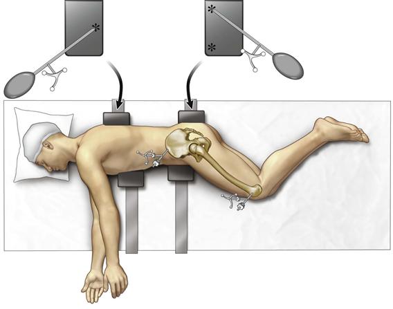
If the operation is to be done with the patient in the lateral position, the patient is now turned to the lateral position and is fixed securely with two anterior and two posterior posts (Fig. 74-1). The patient’s skin is prepared with a sterile chemical, and when draped the pelvic array must be draped into the field. The longitudinal axis of the body is measured by touching the posterior pelvic and chest supports, creating a triangle between them (see Fig. 74-1). This axis allows the software to determine the pelvic tilt (APP angle to the body axis). Knowledge of the degrees of pelvic tilt allows the acetabular component inclination and anteversion to be positioned on the coronal plane.

Figure 74-1 Patient properly secured with two padded posts supporting the chest and two padded pelvic supports. The pointer guide (your spoon-shaped instrument) is used to register the longitudinal axis of the body by touching the posterior posts in a triangular shape (asterisks) with two points on the pelvic support and one on the chest support.
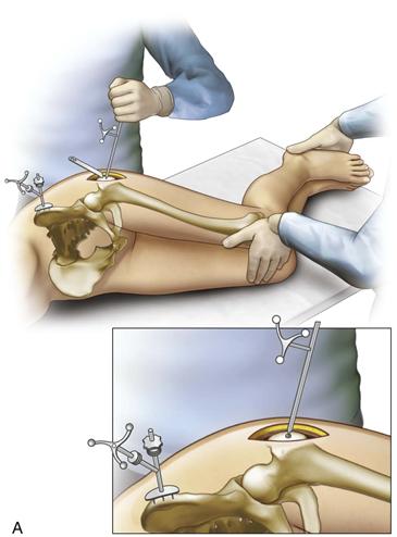
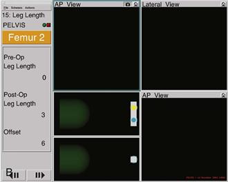
After the incision has exposed the greater trochanter, a small unicortical screw is inserted for measurement of leg length and offset, with the legs aligned on top of each other by the tibial tubercles and heels. This measurement is repeated after reconstruction of the hip is completed and reduction of the hip is done. Both legs are kept in the same position, as for the measurement before reconstruction. The computer will report the change in hip length and offset (Fig. 74-2A and B). It is critical that the same assistant align the leg position for measurements before and after reconstruction.


Figure 74-2 A, A pelvic array is fixed to the iliac crest by three pins. A 3.2-mm screw is inserted into the prominence of the greater trochanter as a reference site for measuring leg length and offset. The pointer guide touches the screw head to register preoperative values into the computer and is touched again after reconstruction to obtain the change in length and offset. B, The legs are overlaid by aligning the patellae and the heels during length and offset measurements. This ensures that the leg is in the same position. The pelvic array is seen on the iliac crest. A retractor exposes the screw, which the pointer guide touches.
Femoral Preparation
No matter the approach used, the femoral neck is cut at the level determined by the surgeon. The femur is prepared first; this represents a paradigm change in conventional hip replacement.16 Preparing the femur first allows the surgeon to estimate femoral anteversion and position the cup to provide a correct combined anteversion of mean 37 ± 12 degrees. The femoral component anteversion can be more accurately measured by computer navigation, as we have done,2,16 but this requires pins in the femoral diaphysis, and we have learned that these pins cause residual pain for 6 to 8 weeks for many patients. Because the femoral anteversion can be estimated within 5 degrees with experience, we have stopped measuring femoral anteversion with navigation.
Acetabular Preparation
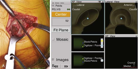
The acetabulum is exposed by retraction of the femur anteriorly or posteriorly, depending on the approach. We use the posterior approach, and this will provide the basis of our description. If difficulty is encountered with anterior retraction of the femur, the surgeon should release the anterior-superior capsule and the reflected head of the rectus muscle; this will facilitate the maneuver. With the acetabulum in full view, the labrum is excised, as is the pulvinar from the cotyloid notch. Removal of the pulvinar from the cotyloid notch allows registration of the cortical bone of the notch, and this enables the software to calculate the medial wall of the anatomic acetabulum by combining these points with those on the acetabular wall. Sixteen points are taken on the walls, while osteophytes are avoided (Fig. 74-3A). Four additional points are taken in the cotyloid notch. These 20 points allow the software to compute the anatomic center of rotation and the acetabular bony position relative to the pelvis (Fig. 74-3B). Measurement of the longitudinal axis of the body and computer determination of pelvic tilt, which was done by touching the posterior supports, allow the cup to be positioned in the combined anteversion safe zone according to the axis of the body (functional position), rather than just in relationship to the pelvis (anatomic plane).

Figure 74-3 A, Intraoperative view of the pointer guide touching the periphery of the acetabulum. The central cotyloid notch is avoided for this measurement, as are osteophytes. B, After 16-point registration of the acetabulum, the computer screen shows the acetabular center of rotation in the two planes. Four additional points in the cotyloid notch show the medial wall. On the left side of the screen, in the box under the word “center,” the diameter of the acetabulum is given (52 mm in this patient).
Stay updated, free articles. Join our Telegram channel

Full access? Get Clinical Tree


