Biomechanics of the Artificial Hip Joint
Georg N. Duda, Christian König, Georg Bergmann, Stephan Tohtz, Carsten Perka and Markus O.W. Heller
Key Points
Introduction
Long-term survival of the artificial hip joint is influenced by several factors, including prosthesis design,1,2 quality of surrounding bone stock,3 degree of patient activity,4 and surgical aspects such as orientation of the implant.5 Furthermore, it is accepted that modifications in joint geometry secondary to hip arthroplasty have an impact on joint function,6 primary stability,7 and bone remodeling.8
To improve the long-term survival of joint replacements and to minimize rehabilitation time, a fundamental understanding of the biomechanics of the joint is necessary. This becomes even more relevant in revision cases. Such an understanding is important because the geometry of the artificial hip can differ from the preoperative condition, and this may lead to significantly altered mechanical boundary conditions in the joint. During total hip arthroplasty (THA), surgeons often aim to optimize function and loading conditions through specific geometric alteration of the musculoskeletal structures. However, without detailed knowledge regarding in vivo musculoskeletal loading, neither the short-term nor the long-term consequences of these intraoperative alterations can be accurately predicted.
This chapter aims to provide a basic explanation of the biomechanics of the artificial hip and to assess possible consequences when the geometry of the joint is altered. Even though the complex biomechanical analyses introduced in this chapter may be difficult to perform in daily clinical practice, an understanding of basic musculoskeletal mechanisms may help the clinician to incorporate biomechanical principles in the individual treatment of patients. This chapter also aims to raise awareness of the importance of preoperative planning for joint replacement. Although it is common to consider geometric aspects of joint reconstruction, planning tools or even navigation systems that consider the biomechanics of the artificial joint are not now a routine component of clinical practice of THA.
To fully comprehend the biomechanical consequences of changes in joint geometry, an appreciation of the internal loading conditions of the joint must be gained. Load transmission via the joints and in long bones has long been considered of importance for clinical evaluation and biomechanical analysis.9 However, illustrations of loading conditions in the femur have often been oversimplified by displaying only the hip contact force acting on the femoral head. This tends to leave the impression that forces are transmitted through the bone and “leave” the bone at its distal end. This concept has widely influenced the design of experimental apparatus used in fatigue testing,10 evaluation of the primary stability of implants,11 and remodeling analyses.12 As described in greater detail in the following pages, in vivo measurements and numeric analyses of musculoskeletal loading show that load transfer is modified along the entire length of the bone through continuous action of muscles. To understand the femoral load state, the original misconception should therefore be revised to reflect the close relationship between joint contact forces and muscle action.
The Basic Science of the Hip Joint
Musculoskeletal Loading Conditions at the Hip
Background
Knowledge of external loads on the body and their corresponding internal counterparts is essential for gaining more detailed information on the loads that an artificial hip joint has to bear. Because these internal and external loads define mechanical boundary conditions in the joint, this knowledge also provides the basis for investigating and understanding biological processes that occur during bone healing and remodeling.13,14
In 1870, Julius Wolff described, for the first time, the interrelationship between loading, stress, and strain in anatomic structures; he later manifested this description in the so-called Wolff’s laws.15 Based on Wolff’s investigations, Koch published the first analytical determination of loading conditions in long bones.16 The remarkable role that muscles play in the loading scenario of long bones was first described later by Pauwels.17 Using the abductors and the iliotibial tract, Pauwels illustrated the way in which muscle forces reduced internal loading within the bone. In numerous examples, Pauwels also described how muscles and tendons counteracted bending moments generated at the hip through the action of body weight by examining areas of tensile and compressive strain within the cross-section of long bones.18
Although it is now known that the contributions of muscles are essential in the mechanical loading of bones, the actual forces occurring in vivo are hardly accessible. Direct measurement of the coordinated action of all muscle forces in vivo is impossible, as ethical considerations discourage the use of invasive methods in humans. Therefore, the only opportunity to estimate the complex distribution of muscle forces is offered by computer analysis.
In various studies, optimization algorithms were used to solve the distribution problem and to simulate loading conditions at the hip.19–30 A common approach to validating these models was comparison of muscle activation patterns obtained from simulation versus measured muscle activities as determined by electromyography (EMG). However, this method does not allow quantitative validation of musculoskeletal loading conditions. Instrumented implants provide hip contact forces for different activities for individual patients in vivo.31–37 An additional method of validating predicted musculoskeletal loading conditions is comparison of calculated hip contact forces versus in vivo measured forces. Hip contact forces measured with instrumented prostheses have been compared with results of computer modeling in the same patients by Heller and coworkers38 and Brand and coworkers.34 The latter study measured hip contact forces 58 days postoperatively, and gait analysis was performed 90 days postoperatively. Therefore, a cycle-to-cycle comparison of measured and calculated hip contact forces was not possible. Heller and coworkers38 used a cycle-to-cycle comparison of measured and calculated hip contact forces to attain a basic understanding of the biomechanics of the artificial hip joint.
Determination of Internal Loading Conditions
To analytically describe musculoskeletal loading conditions within the body, the movement of the extremities and the external loads must be known. This information can be gained through gait analysis, whereby movement of the lower extremity and ground reaction forces on the feet can be measured, even for large patient cohorts.39 Based on this individual measurement of movement and external loads, resulting joint reaction forces can be calculated using an inverse dynamics approach.40 Here, joint loads represent the sum of all forces and moments at the joint generated by muscular activity. With the use of optimization algorithms, a “reasonable” solution can be found for a pattern of muscular activity that can balance these forces and moments.19,41 However, it is necessary to validate these mathematical analyses against in vivo data to verify the plausibility of the results.34 One option for gaining such in vivo data is the use of telemetric implants as, for example, developed by Bergmann and colleagues.42
Heller and coworkers38 followed such an approach in their study and verified their results calculated with a musculoskeletal model by using hip contact forces measured with telemetric hip implants. A full description of the musculoskeletal model of the lower limb,38 muscle and joint contact force calculations,43 and collection of gait data42 can be found in greater detail in the literature and is briefly summarized here. Four THA patients with telemetric prostheses (11 to 31 months postoperatively) were considered in the study. For all four patients, individual anatomic measures were determined from computed tomography (CT) scans and radiographic findings (pelvic width and depth; femoral, tibial, and foot length). In addition, neck length, neck stem, and cervicodiaphyseal and anteversion angles were recorded. Gait analysis data for walking and stair climbing42 (i.e., ground reaction forces, limb segment positions, velocities, and accelerations) were determined simultaneously with the use of in vivo hip contact forces. A computer model of the human lower extremity (CT data; Visible Human Project, National Library of Medicine), including bone surfaces and muscles, was developed (Fig. 2-1). Where appropriate, muscles were wrapped around bony contours. This model was then scaled to match the individual anatomies of the four different patients. Muscle and joint contact forces were calculated throughout the gait cycle for both walking and stair climbing using an optimization algorithm that minimized the sum of muscle forces. For validation, hip contact forces calculated for individual gait cycles were compared directly with corresponding in vivo measurements, revealing good agreement.
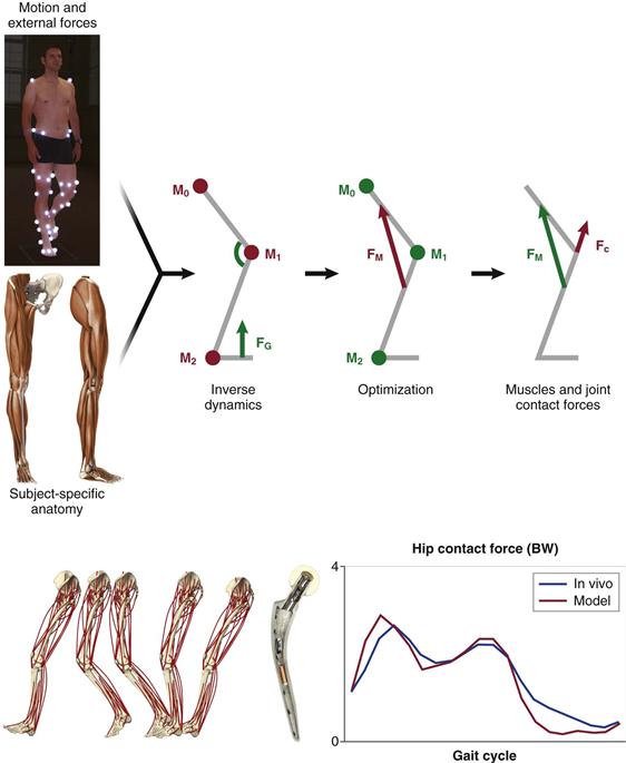
Figure 2-1 Schematic representation of patient-specific determination of internal loading conditions. Gait analysis data are recorded for a subject (i.e., ground reaction forces and moments), together with limb segment positions from which velocities and accelerations are determined (upper left). Using key anatomic measures of the patient’s anatomy (pelvic width and depth; femoral, tibial, and foot length; femoral neck length; cervicodiaphyseal and anteversion angles), which can be derived from medical imaging data, a patient-specific musculoskeletal model is generated (lower left). Combining these data in an inverse dynamics approach provides access to intersegmental resultant joint moments. Muscle and joint contact forces are then calculated using an optimization algorithm, which minimizes the sum of muscle forces to balance these moments (upper right). To validate the predictions of the musculoskeletal model, hip contact forces calculated for individual gait cycles of four patients were compared directly with corresponding in vivo forces measured with telemetric hip implants (lower right).
With the use of such validated musculoskeletal models, the biomechanics of the artificial hip can be explored in greater detail. Variations in numerous parameters describing the anatomically reconstructed artificial hip can be simulated using the computer model, including, for example, variations in prosthesis placement and orientation. Furthermore, although in vivo measurements provide limited data, describing internal forces acting at a single location, musculoskeletal models that predict muscle and joint forces throughout the entire extremity provide a means to analyze and better understand loading conditions throughout the entire bone.
Biomechanics of the Proximal Femur
The musculoskeletal model has revealed44 that internal loading of the femur is predominantly characterized by axial compression (Fz), with small mediolaterally (Fx) and anteroposteriorly (Fy) oriented shear forces (Fig. 2-2). During walking, both compressive and shear forces are largest at the femoral head and decrease distally toward the diaphysis. This is related to the relatively large activity of the abductors during gait.45–47 Bending moments in the femur are dominated by the frontal plane bending moment (My), and axial torsion (Mz) is the smallest of all moments (see Fig. 2-2).
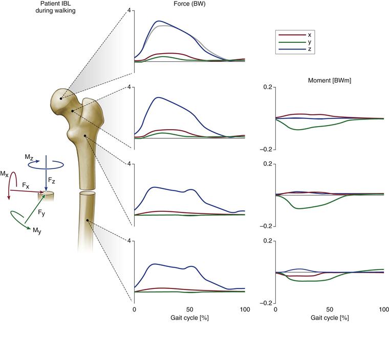
Figure 2-2 Internal loads at four levels of the femur during the walking cycle are shown for one specific subject. Forces are given in multiples of body weight (BW), moments in body weight meters (BWm), and time in percent of walking cycle, starting with heel strike. Dark graphs, Fx is the shear force from medial to lateral; Fy is the shear force from anterior to posterior; and Fx is the axial compression force from proximal to distal. Mx is the backward acting bending moment in the sagittal plane, My is the inward acting bending moment in the frontal plane, and Mz is the torsional moment in the transverse plane. The moments at the head center are zero. Light graph, In vivo measured hip contact force component is Fz. All signs are reversed for the proximal sides. (Redrawn from Heller MO, Bergmann G, Deuretzbacher G, et al: Influence of femoral anteversion on proximal femoral loading: measurement and simulation in four patients. Clin Biomech [Bristol, Avon] 8:644–649, 2001.)
Even though patterns differed over time because of patients’ individual gait characteristics,48 combined with their postoperative rehabilitation, load magnitudes appeared to be comparable between the four patients during walking (Fig. 2-3) and stair climbing (Fig. 2-4). However, large differences were found in the magnitude of compressive forces acting down the femur (Fz), where, during stair climbing, forces peaked in the diaphyseal part of the bone because of contraction of the vasti.49,50 In addition to observed general patterns of forces and moments acting within the femur, patient-specific loading characteristics were apparent. Variation was noted, not only in the head, but throughout the length of the bone. The importance of considering the muscle contribution when analyzing mechanical loading is underlined by the fact that the bending moments determined were considerably smaller than those predicted by previous analyses, which neglected muscle forces.16,18,51
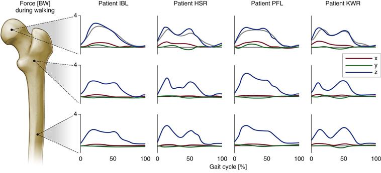
Figure 2-3 Internal forces at three levels of the femur, values in body weight (BW). Results are shown for four patients during walking (for further explanation, see Fig. 2-2). (Redrawn from Heller MO, Bergmann G, Deuretzbacher G, et al: Influence of femoral anteversion on proximal femoral loading: measurement and simulation in four patients. Clin Biomech [Bristol, Avon] 8:644–649, 2001.)
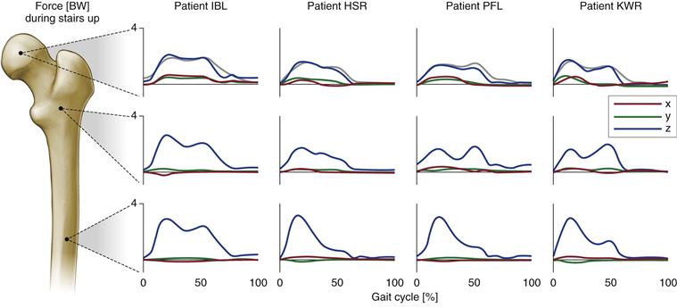
Figure 2-4 Internal forces at three levels of the femur, values in body weight (BW). Results are shown for four patients during stair climbing (for further explanation, see Fig. 2-2). (Redrawn from Heller MO, Bergmann G, Deuretzbacher G, et al: Influence of femoral anteversion on proximal femoral loading: measurement and simulation in four patients. Clin Biomech [Bristol, Avon] 8:644–649, 2001.)
Generally, analyses revealed that higher hip contact forces occurred during stair climbing activities than during level gait in all four patients,42 corresponding to larger internal forces and moments. It has to be kept in mind, however, that fast walking causes forces at the hip joint that are higher than during stair climbing.31 The general ratio of compression to shear forces and of bending to torsional moment remained similar throughout. The literature suggests that specific situations such as stumbling are capable of causing excessive hip contact forces.32 Analysis of musculoskeletal interaction suggests that under these conditions, muscle activity alone is capable of generating extreme joint forces. Similarly, all other bony regions spanned by activated muscles may become excessively loaded during activities such as stumbling.52 If muscles are activated to their full potential, they may produce not only maximal forces at the joints and extreme compression forces in the bone but also excessive bending and shear forces. In patients with joint arthroplasty, such high contact forces and bony loads may endanger the bone implant interface and the longevity of the implants; this is addressed later in the chapter.
Influence of Joint Reconstruction on Biomechanics of the Artificial Joint
Reconstruction of the Joint Center
It has been suggested that implanting the acetabular cup of the artificial joint in a cranialized position will lead to unfavorable loading conditions in the joint,53 which are associated with disadvantageous long-term clinical results.54,55 These observations led to additional studies evaluating the influence of acetabular cup placement on loading conditions at the hip, as well as on the long-term polyethylene wear of the cup itself.56
In a musculoskeletal model, the acetabular cup was translated up to 10 mm in the medial, lateral, anterior, posterior, cranial, or caudal position. For these altered positions of the hip center, the mean joint contact force during the whole gait cycle and peak hip joint contact forces were determined during walking and stair climbing activities and were compared with those forces occurring in an anatomically reconstructed acetabulum.
This analysis revealed that mediolateral deviation from the anatomic location of the hip center has the greatest influence on loading conditions in the hip (Fig. 2-5). The mean joint contact force, which summarizes the net change in joint loading over the full cycle, decreased when the joint center was medialized, while lateralization by 10 mm led to an increase in mean contact forces (walking, 8%; stair climbing, 7%). A cranialized joint center slightly decreased and a 10-mm caudalized joint center increased mean contact forces by 1% during a cycle of normal walking, and by 2% for a stair climbing gait cycle. Deviation in the anterior-posterior direction resulted in changes to the mean contact forces, which stayed below 3%. Changes in peak hip contact forces during the gait cycle were greater than those noted in mean contact forces over the entire cycle, and the largest increase in peak joint contact force was seen in a lateralized hip center (+14%).
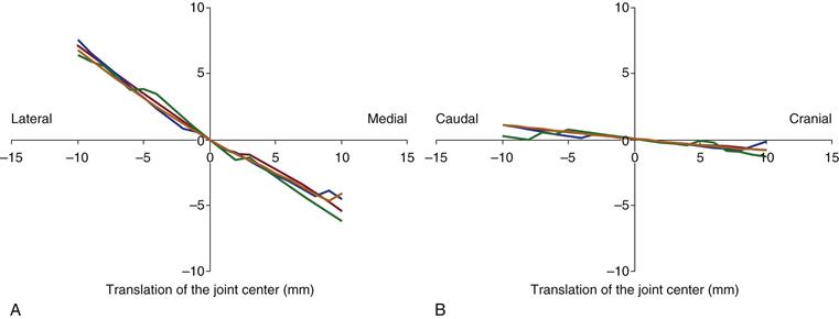
Figure 2-5 Influence of cranial-caudal (a) and mediolateral (b) translation of the hip center on joint contact forces in the hip. Displayed is the change in mean hip contact forces during a walking cycle in relation to values in the anatomically reconstructed joint. (Modified from Heller MO, Schroder JH, Matziolis G, et al: [Musculoskeletal load analysis: a biomechanical explanation for clinical results—and more?]. Orthopade 3:188, 190–194, 2007.)
Among 109 retrospectively analyzed primary hip replacements with an average follow-up of 9.3 years,57 the joint center was anatomically reconstructed in 61% (n = 66) (group I). The joint center was cranialized in 29 patients (27%) (group II), medialized in 10 patients (group III), and caudalized in 4 patients (group IV). Although no significant difference was observed between any of the groups in terms of Harris hip scores, and no difference in the linear polyethylene wear rate was found between groups I and II, the group with the medialized joint center (group III) and with lower joint contact forces exhibited significantly lower wear (0.077 mm3/year) than the group with an anatomically reconstructed joint (group I; P = .018). Analyses56 therefore revealed an interrelation between the location of the artificial hip joint center, joint contact forces acting in the artificial hip, and wear of the polyethylene inserts.
Related posts:


Stay updated, free articles. Join our Telegram channel

Full access? Get Clinical Tree


