BIOMECHANICS
I. Introduction—Biomechanics of the musculoskeletal system is the study of the effect of forces on the musculoskeletal system. Forces may be generated by muscle contractions or from externally applied sources. When a force is applied by an outside source, acceleration occurs and thus movement of an extremity. External forces can be explained using Newton’s laws of motion. The application of external loads on materials and their effect is determined by the stress and strain of the material.
A. Definitions
1. Biomechanics—Biomechanics is the study of the effects of forces on the musculoskeletal system.
2. Statics—Statics is the branch of physics concerned with the analysis of loads (Force = Torque/Moment) on physical systems in static equilibrium.
3. Kinematics—Kinematics is a branch of dynamics that describes the motion of objects without consideration of the circumstances leading to the motion. Motions may be within the body (joint kinematics) or may be during gait.
4. Scalars—Scalars have magnitude but no direction. These include mass, age, time and height.
5. Vectors—Vectors have magnitude and direction. These include force, velocity, acceleration, torque, stress, and strain. Vectors may be resolved into components that are perpendicular to each other, so that one is normal (perpendicular) and the other is parallel to a plane.
B. Newton’s Laws—Newton’s laws form the basis of biomechanical principles; they are:
1. A physical body will remain at rest, or continue to move at a constant velocity along a straight path, unless an external net force acts upon it.
2. The rate of change of momentum is proportional to the resultant force producing it and takes place in the direction of that force (Force = Mass × Acceleration).
3. Every action has an equal and opposite reaction.
C. Forces
1. A force is the quantity that changes velocity and/or the direction of an object (i.e., the vectors having magnitude and direction). The magnitude of a force is equal to the mass of the object multiplied by the acceleration of the object. The unit of force is kg m/s2, which is a newton (N).
2. Forces, stresses, and strains can be resolved into normal and shear components with respect to any arbitrary plane at any point of application on the structure.
3. Normal stress—Normal means perpendicular to a particular plane. Normal stress may be compressive or tensile.
4. Shear stress—Shear means parallel to a particular plane.
D. Moment
1. A moment is the quantity that changes the angular velocity. It is the action of a force that tends to rotate an object about an axis.
2. Moments are vectors. The magnitude of a moment = force × perpendicular distance to the axis of rotation; that is, it is equal to the mass moment of inertia of the object and its angular acceleration. The unit of the moment is the newton-meter (N·m). The direction of the moment is given by the right-hand rule.
E. Equilibrium
1. The concept of static equilibrium is used for solving problems related to orthopaedic biomechanics.
2. Static equilibrium is the situation in which no acceleration occurs in the system. (The system is at rest or moving at a constant velocity.)
3. Carrying objects—A weight held by the arm creates a moment about the elbow, the magnitude of which is calculated as the product of the force acting on the hand and the perpendicular distance between the line of action of the force and the center of rotation of the joint (Fig. 4-1).
4. Stance—The forces acting about the hip joint during single leg stance include the body weight, abductor muscle force to counteract the body weight, and the vector sum of these forces acting through the hip joint (joint reaction force). The abductor muscle force acts through a shorter moment arm than the body weight force; thus, the abductor muscle forces are approximately twice the body weight force. The result is the joint reaction force and is 3 to 4 times body weight. Using a cane in the opposite hand reduces the abductor muscle force and thus the joint reaction force by providing a moment that counters the body weight moment.
5. Stair climbing—Stair climbing with the knee less flexed reduces the moment arm of the body weight force.
F. Linear Elasticity
1. Linear elasticity is the model for material behavior and has three basic assumptions: stress and strain are proportional to each other; this proportionality constant is the modulus of elasticity, E (Young’s modulus); and strain is reversible when the stress is removed. The rate of application of the load does not have an effect. If stress is plotted against strain, the relationship between the calculated stress and the measured strain is linear, so the ratio of stress to strain is constant. The ratio of stress to strain depends on the material being tested and not the shape of structure being tested.
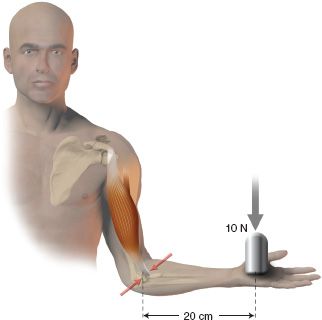
FIGURE 4-1 A 10-N weight in the hand creates a 2-N m moment about the elbow.
2. Stress = elastic modulus × strain. Stress is the internal reaction to an externally applied force (or torque) distributed over the cross section of the material (σ = Eε). Testing of a material is usually done as an axial tensile load. The load is resisted internally over the surface of the material’s cross section. Stress on a small piece of cross section is defined as internal force divided by surface area over which it acts; that is, stress = force / area. Unit of stress is N/m2; 1 N/m2 is a Pascal (Pa). A force perpendicular to the cross section is called normal stress. Cross sections that are not perpendicular to the applied load have the force acting parallel to the surface of the cross section and this produces shear stress.
3. Strain—Strain is internal deformation of a material in response to an applied stress; strain = the change in a dimension / the original dimension (Fig. 4-2). This may also be written as the following: normal strain = change in length / unit length. If positive, it is tensile and if negative, it is compressive. Strain is a ratio without units and is presented as a percentage or micro strain. Shear strain occurs when there is a change in the angle between two adjacent surfaces that were perpendicular to each other. Shear strain is expressed in units of radians.
G. Geometric Properties
1. Cross-sectional area is important in resisting axial loading (tension or compression).
• Axial load is the simplest loading that a structure can experience. As an example, ligaments support loads in tension and this is called tensile axial loading. The ligament elongates because the fibers elastically deform (Fig. 4-3).
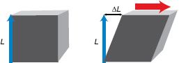
FIGURE 4-2 When load is applied parallel to the face of a cube of material, the cube distorts, so that the edges of the cube are no longer right angles. The distortion (approximately equal to ΔL, divided by L in radians) is the shear strain, where L is the length.
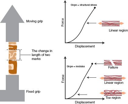
FIGURE 4-3 A patellar ligament is subjected to a uniaxial tensile test. The stiffness is the slope of the linear portion of the resulting force–displacement graph. If load is converted to stress and displacement to strain, the slope of the stress–strain graph is the elastic modulus of the ligament tissue. The strength is the maximum stress that the ligament can withstand before rupture.
(a) Structural stiffness is the ability of the structure to maintain its shape while under load. Structural stiffness can be altered by changes in geometry or by elastic modulus.
(b) The strength of a structure is defined as the maximum load that the structure can withstand without material failure.
• Centroid is the geometric center of the area or of the volume.
• Bending loads produce stresses in a material (e.g., bone, and therefore distribution of the loads through the structure).
(a) Application of a bending load to a rectangular structure results in the slight deformation of the material such that there is tension on the convex side and compression on the concave side. The mid portion of the structure (the neutral axis) experiences no tensile or compressive stress (Fig. 4-4).
(b) Material in the rectangular structure away from the midline has higher stresses than material at the midline (no stress).
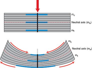
FIGURE 4-4 Under the influence of bending loads, the longitudinal lines curve and the transverse lines are no longer parallel. The line segment mt lengthens, mc shortens, and mn does not change in length. The pattern of stress is therefore a linear distribution. Material further away from the midline has higher stress than the neutral axis, which experiences no stress.
(c) The distribution of mass about the midline is described by the area of moment of inertia (I). This is calculated by adding each increment of cross-sectional area in the structure multiplied by the square of the distance from the increment of cross section to the neutral axis. I = (1/12) wd3 where w is width and d is thickness. Doubling the thickness of the rectangular structure increases resistance to bending by a factor of 8.
(d) The strength of a beam is the largest bending moment a beam can carry without causing stress in the material to exceed a critical limit. In biologic structures and implants that undergo cyclic bending loads, the critical limit is the fatigue strength of the material.
(e) Bending loads applied to long bones usually result in the intensities of the induced compressive and tensile stresses to be almost equal because of the relative symmetry of the bones. Bone is weaker under tension (tensile loading) than under compression (compressive loading), and failure starts in the region of highest tensile stress.
• Torsional load is another mode of loading. Torsional loads produce moments that tend to twist the structure.
(a) A common occurrence is torsional loading of the tibia that occurs while skiing. A load applied perpendicular to the ski tip produces a torsional moment, resulting in external rotation of the tibia. Using static equilibrium, there is a moment applied to the internal cross section of the tibia proximally that is equal to the external applied moment but in the opposite direction. The internal torque is constant along the length of the tibia. This is different from bending moments, which vary along the length of the bone.
(b) Torsional load applied to a beam or cylinder leads to one end rotating relative to the other. A straight longitudinal line on the surface will twist into a helix providing a helix angle α. The total deformation (θ) is proportional to the applied torque and the length of the structure (L
Related posts:


Stay updated, free articles. Join our Telegram channel

Full access? Get Clinical Tree


