Fig. 1
Clinical IGS scene
Augmented reality (AR), which can improve accuracy of the decision-making in IGS, is a visualization technique to merge virtual computer-generated images into real surgical scene seamlessly and accurately [4]. Therefore, alternate viewing between images displayed and the actual surgical area is no longer required. Therefore, surgeons’ hand-eye coordination is improved [5]. Two crucial requirements for medical AR system are “right time” and “right place”. Both of them ensure the correspondence between real intervention environments and virtual images dynamically. In order to achieve these goals, a variety of techniques are applied to medical AR systems, such as 3D positioning techniques, intra-operating imaging techniques and 3D visualization techniques [6].
Most studies on AR in surgical environments focus on the usage of AR surgical microscopes, head-mounted displays (HMD) and semi-transparent mirrors overlay systems [7]. They use optical or video-based methods to achieve virtual message injection. Compared with the restriction of the position between the eye and the eyepiece or the screen, image overlay can provide a larger viewing angle and a more comfortable visual perception for multiple observers.
By using image overlay techniques, surgeons look through a semi-transparent mirror and see the reflected virtual images overlaid onto the real scene. Virtual images can be 2D cross-sectional images, 3D surface or volume rendering results and autostereoscopic images. Proper geometrical relationship between the image display and the semi-transparent mirror with accurate patient-image registration ensures that the reflected images appear in a correct position with the appropriate scale. Image overlay guarantees that augmented images can be observed by multiple surgeons, without any assistant tracking devices or special glasses wore by observers [3]. A prototype 2D image overlay system proposed in [8] applies intra-operative CT slices as the intervention guidance, and conducts experiments with phantoms and cadavers. Evaluations prove that this overlay system optimizes spinal needle placement with conventional CT scanners.
Until now, image overlay has been applied in phantom, cadaver or animal studies of knee reconstruction surgery [9], needle insertion [8], dental surgery [10] and some other MIS. The spatial accuracy of virtual images is one of the major determinants of safety and efficiency in surgery, while medical images including cross-sectional, surface or volume rendering image shown in 2D display can’t provide adequate geometrical accuracy during precision treatment. This forces surgeons to take extra steps to reconstruct the 3D object with depth information in their mind and match the guidance information. Current 3D visualization techniques in medical AR navigation systems can provide depth perception based on geometry factors such as size, motion parallax and stereo disparity. However, even though all positions are computed correctly, misperceptions of depth may occur when virtual 3D images are merged into real scene [11]. In order to provide a precise depth perception for augmented reality in image-guided intervention, autostereoscopic image overlay is a good solution.
This chapter is organized as follows. Section 2 describes the IV image algorithm, device structure and tracking methods in IV image overlay system. Section 3 introduces the patient-3D image registration and visualization methods used in IV image overlay system. Section 4 shows some typical applications of IV image overlay in orthopaedic interventions. Section 5 summarizes characters of different 3D AR techniques. Section 6 makes a discussion on the current challenges of 3D AR in orthopaedic interventions and concludes the chapter with a brief summary.
2 IV Image Overlay for Orthopaedic Interventions
Autostereoscopic image overlay can superimpose a 3D image onto the surgical area. Autostereoscopic display techniques include lenticular lens, parallax barrier, volumetric display, holographic and light field display. Among all mentioned techniques, integral photography (IP) is a promising approach for creating medical-used autostereoscopic images. The resulting 3D images have arbitrary viewing angles by a series of elemental images covered by a micro convex lens array. The concept of IP was proposed in [12] by Lippmann. IP encodes both horizontal and vertical direction information so that it can generate a full parallax image. The traditional IP technique records elemental images on films, which cannot satisfy real-time IGS applications. IV introduced in [13] uses fast rendering algorithm to accelerate elemental image generation and replaces the film with a high resolution liquid crystal display (LCD) display, which make IV adoptable in clinical AR guidance. Compared with a 2D image or binocular stereoscopic images, it has outstanding features. Firstly, the spatial accuracy of the image is better, especially in depth. Secondly, images can be simultaneously observed by multiple people with less visual fatigue. We will introduce the general system configuration of IV image overlay in the following section.
2.1 IV Image Rendering and Display
The IV overlay system creates 3D images of the anatomical structures around the surgical area and the surgical instruments. Data sources of IV images can be pre-operative/intra-operative medical images or computer-aided design models. Images are fixed in space and observers can see different images from different viewing angles. Therefore, different views of an IV image can be seen in various positions, just like a real 3D object in space.
The calculation of elemental images can be achieved by surface rendering or volume rendering methods. Surface rendering implements reverse mapping from spatial computer-generated (CG) surface model to generate background image. This mapping procedure is conducted from many different predetermined angles. Generation of elemental images is based on the pixel redistribution algorithm [14, 15]. The algorithm separates the coverage display area into M × N small elements depending on the pre-defined IV image solution. Pixels in different rendered images obtained from the homologous viewport are realignment into elemental image obeying a crossing redistribution rule. Brightness and color of each pixel are determined by the property of the corresponding surface point of the CG model.
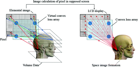
Volume rendering simulates that there are rays emitted from each pixel in the LCD display and getting a corresponding point behind each lens at the end. This procedure generates more accurate IV images than surface rendering since every ray is considered. The principle of IV volume rendering is shown in Fig. 2. Each light emitted by pixels follows the particular direction that connects the corresponding pixel and lens’center. Each point in space image is reconstructed at the same position by the convergence of rays from the pixel of elemental image on the display.


Fig. 2
Principle of volume rendering IV: explaining the method to generate and reconstruct a 3D image by IV. Left The principle calculation of elemental image is each point in a voxel data can emit rays pass, which will through the centers of all lenses, and be redisplayed at the back. Right When the elemental image is shown on a flat display covered by a lens array, a corresponding 3D image can be reconstructed
3D IV images require real-time updating when the surgical scene changes. However, IV rendering is computationally costly, as one rendering needs many conventional surface renderings (for a surface model) or numeric ray-casting procedures (for a volume data). Here we introduce a flexible IV rendering pipeline with graphics processing unit (GPU) acceleration [16]. Modern OpenGL has a programmable rendering pipeline, which can be executed on GPUs. Computer-generated IV method proposed by Wang et al. (2014) uses a consumer-level GPU to realize real-time 3D imaging performance with high image resolution [17].
2.2 IV Image Overlay Devices
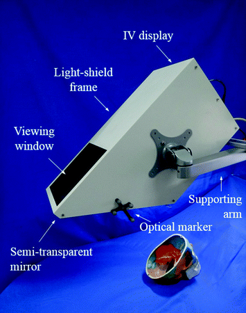
General IV image overlay device consists of an IV display, a semi-transparent mirror, a flexible supporting arm and a light-shield frame with a viewing window [18]. The overview of IV image overlay device is shown in Fig. 3. The spatial relationship between the IV image and its corresponding anatomical structure satisfies mirror image relationship. Surgeons can see the IV image reflected in the corresponding location in the surgical area when looking through the semi-transparent mirror. Working distance between the semi-transparent mirror and the surgical area is adjustable by changing the distance between the semi-transparent mirror and the IV display. The viewing field and viewing angle are limited by the size of the viewing window.


Fig. 3
IV image overlay device
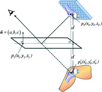
The spatial relationship between the 3D IV image  and corresponding point
  after semi-transparent mirror reflection (Fig. 4) satisfies the following equation [19]:

with

where  is a point on the plane of the semi-transparent mirror,
  is its normal vector and the plane equation is
  .
.

 and corresponding point
  after semi-transparent mirror reflection (Fig. 4) satisfies the following equation [19]:
(1)

(2)
 is a point on the plane of the semi-transparent mirror,
  is its normal vector and the plane equation is
  .
.
Fig. 4
Spatial relationship between 3D IV image and corresponding point after semi-transparent mirror reflection
IV overlay-guided surgical operations will be more convenient when the overlay device can be easily manipulated depending on surgeons’ postures and viewing angle. AR images can be refreshed automatically when the device is tracked during surgery since distance between each point on the target anatomical structures and semi-transparent mirror can be calculated. In this way, correct spatial positions of the IV image are estimated and elemental images will be updated automatically.
2.3 3D Spatial Tracking
A tracking system is necessary in IV image overlay to track surgical instruments, the overlay device and the patient. According to these position data, patient-image registration, intra-operative image registration, IV image rendering and update can be achieved.
The most common clinically used tracking systems are frame-based stereotaxy, optical tracking systems (OTS), electromagnetic tracking systems (EMTS) and intra-operative image-based analysis and tracking method. Frame-based stereotaxy integrates a reference coordinate to access the spatial positions and it is mostly used in oral and maxillofacial surgery. Although this kind of positioning technique proves to have high accuracy and stability in rigid structure tracking, the stereotactic frame may obstruct surgical operation. OTS identifies marker patterns and image features in the visible light range or near-illuminated infrared range, and then determine the pose information. OTS can provide a high positioning accuracy and reliability, but the line-of-sight between the marker and the tracking device has to be constantly maintained. EMTS can avoid line-of-sight problem so it is possible to track the instruments inside patient’s body. EMTS localizes electromagnetic coils in the generated electromagnetic field by measuring the induced voltage. Nevertheless, its limitations include limited accuracy compared with optical tracking owing to field distortions caused by sensitivity to mental sources. Intra-operative imaging modalities get real-time images of the surgical area to track the pose of instruments or anatomical structures, which should be easily distinguished in images. Intra-operative imaging can easily explain the relationship between instruments and structures and be able to achieve surface tracking. At the same time, image information can also be useful in real-time diagnosis and therapy evaluation, but it may increase radiation dosage during surgery.
Most tracking systems need specified markers or sensors, but there are obvious limitations as follows. First, sometimes surgical space is limited or target is not suitable for placing markers. Second, it is difficult to determine the whole pose of a non-rigid tool or anatomical structure according to positions of some separated points. To solve these problems, marker/sensor-less tracking techniques become a hot area of research. Medical imaging and visible light stereo cameras are available to track objects based on image features and motion detection techniques [10]. Research on marker-less tracking, such as interventional needle, teeth, soft tissues, has drawn remarkable attentions. Major limitations of marker-less tracking in clinic are accuracy, computational speed and robustness. With the technical development of medical imaging, pattern recognition, computer vision and other related fields, marker-less based tracking will have a great potential for clinical applications.
Each tracking systems mentioned above has both advantages and disadvantages, hybrid tracking systems combining two or more tracking techniques are needed in order to achieve more reliable performance and larger working space.
3 Patient-3D Image Registration and Visualization Techniques
3D registration in AR interventions means spatial correlation of the reference position of virtual images and the patient. AR systems calculate the posture of both the virtual and actual objects and align them in a spatial position. Patient-3D image registration is based on a set of distinct external geometrical or natural anatomical features and landmarks, which can be accurately identified in both patient and 3D image spaces [20]. In mathematical terms, registration is represented by a linear coordinate transformation, which transforms coordinates between the image data coordinate system and the patient coordinate system using pair-point or surf-matching techniques. The rigid coordinate transformation, which can be represented by a 4 × 4 matrix consisting a 3 × 3 rotation matrix and a 3D translation vector, is solved mainly by minimizing the distance between pair-features using the least-squares fitting algorithm [21]. Following registration and visualization methods can be used in IV image overlay system.
3.1 Marker Based Registration
Accuracy of feature localization and extraction is always the main factor that significantly affects the registration result. Reference frame in stereotactic surgery is one early solution to locate accurate and stable positions of corresponding external points from image and patient in surgical interventions [22]. However, the frame may cause image artifacts during medical image acquisition and reduce the accuracy of registration. Besides, reference frame can bring a lot of uncomfortableness and inconvenience to patients and surgeons.
For the sake of patient’s burden and surgical simplicity, reference in positioning becomes much smaller and lighter when using markers instead of frames. Reference markers, which can be mounted on a pointer held by the surgeons, patient and image visualization device, are widely used in orthopaedic interventions. A tracking system is applied to measure the positions of these targets according to the positions of markers.
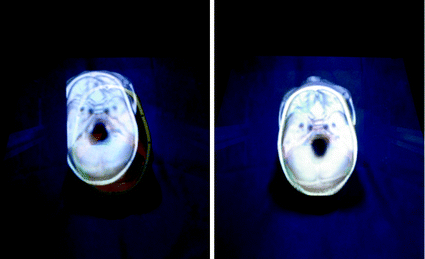
Two main methods are used to acquire the positions of homologous points. Firstly, specific skin-affixed markers or bone-implanted markers, which can be recognized easily in medical images, are mounted on the patient during imaging procedures. At the same time, the positions of markers can also be determined during the surgery. When markers can be directly tracked, intra-operative patient movements can be tracked and become a real-time feedback to update the image-patient relationship. Bone-implanted markers offer a more stable and precise positioning result than skin-affixed markers since error caused by tissue shifting is almost avoided [21]. The simpler method is to depend on natural anatomical features on the surface such as tip of nose, center of two eyebrows on the surface or the distinct features of bones, which can be identified in images and observation. Positions of these feature points can be determined by putting the tip of a tracked pointer on the targets. Thus, it is not necessary to fix marker on patients, avoiding the invasiveness in imaging and surgery. Figure 5 shows the patient-3D IV image registration of a skull phantom.


