Fig. 1
Depth of the resection of the proximal head to allow for the femoral component thickness
Although the published results for offset and leg-length changes following HRA are often significantly smaller compared to THR studies, they still indicate non-optimal postoperative biomechanical reconstruction of the hip. In particular the decrease in femoral offset can negatively influence the hip’s function.
1.2 Acetabular Component Alignment
Although the role of the femoral component alignment with respect to postoperative outcome is well known, the role of acetabulum component alignment is less certain. Recent studies suggest that improper alignment of the acetabulum component might be connected to increased metal ion levels, as well as unexplained postoperative pain. Abnormal periprosthetic soft-tissue lesions (also know as pseudotumor, or adverse reaction to metal debris) have been reported after metal-on-metal HRA with an incidence rate of up to 4 % [25] for asymptomatic hips and were linked to an increased blood, serum and hip aspirate level of cobold (Co) and chromium (Cr) [26, 27]. This correlation indicated that these abnormal periprosthetic soft-tissue lesions could have been the result of increased component wear, a hypothesis confirmed in retrieval studies [28, 29]. These studies also indicated that edge-loading2 with the loss of fluid-film lubrication may be a likely reason for the wear. Follow-up studies have investigated this connection successfully [30, 31]. Various authors have found connections between acetabulum component alignment and the occurrence of edge-loading and high metal-ion levels [27, 31–34]. Recent publications investigate optimal acetabulum component alignment. Langton et al. concluded [27] as a result of an in vivo study that there is a correlation between acetabulum inclination angle and high levels metal ions, but that the maximum limits for inclination depended on the prosthesis type. In 2013 Liu and Gross [35] suggested that the “safe zone” for the acetabulum inclination angle varies depending on component size. In 2015 Mellon et al. [12] suggested that optimal acetabulum component alignment is patient-specific.
1.3 Image-Guided Hip Resurfacing
Most of the limitations and problems discussed above are controlled by the surgeon’s actions intraoperatively, with only small margins of error. Therefore, it is not surprising that HRA is deemed a technically challenging procedure with a significant learning curve [11, 36]. Various authors have discussed the advantages of using image-guided, or computer-assisted systems to help surgeon improve the accuracy of HRA.
In 2004, the first clinical results using a fluoroscopy-based navigation system for positioning of the femoral component during hip resurfacing was published [37]. In this study, four intraoperatively registered fluoroscopy images of the hip were used to navigate the insertion of the femoral central pin. Deviation between the intraoperative targeted and the postoperatively achieved central pin alignment in 31 cases were measured using standard postoperative x-rays. The reported average was 2.6°, with no postoperative complications reported. However, the authors did identify an increase in operating time of 10–15 min in the last 10 cases of the series.
El Hachmi and Penasse [38] compared mid-term postoperative outcomes between patients where the conventional method for femoral guide pin placement was used and patients, in which the femoral guide pin was placed using the BrainLab Hip Essential navigation system (BrainLAB AG, Feldkirchen, Germany). In this imageless navigation system a point/surface acquisition is used to generate a three-dimensional (3D) model of the femoral head and neck and to measure the anatomical 3D neck-shaft angle. Although patients from both groups showed significant mid-term clinical improvement, the authors found a significant reduction of outliers in femoral pin placement for the navigated group in both anterio-posterior (AP) and lateral postoperative x-rays.
In a similar study by Bailey et al. [39], 37 patients who underwent HRA, in which the femoral central pin was navigated using the imageless BrainLab Ci ASR navigation system (BrainLAB AG, Feldkirchen, Germany), were followed up with a 4-month postoperative CT scan. The measured average deviation between the targeted and postoperatively measured femoral component angle in the frontal plane was 0.5°.
In 2007, Hodgson et al. [40] reported improved repeatability in varus/valgus placement of the femoral central-pin when using a CT-based, opto-electronic navigation system versus manual technique. Further, there was no significant dependence on surgeon skill level (in contrast to the manual technique), and surgical time was significantly reduced in the navigated group. However, the authors of this in vitro study also noted a reduced reproducibility in version alignment of the central-pin of the navigated group, compared to the manual group.
The influence of using a navigation system on the learning curve for femoral central-pin placement during HRA was investigated in an in vitro study by Cobb et al. [41]. Students inexperienced in HRA performed central-pin placement, either with conventional methods or by using the CT-based, mechanically tracked Wayfinder system (Acrobot Co Ltd, London, UK). After each procedure the femur model was reregistered and a CT-based navigation system (Acrobot Co Ltd, London, UK) was used for 3D evaluation of the pin placement. The authors found that students using the navigation method performed the placement three times more accurately compared to the non-navigated group, and suggested that navigation may play a major role in reducing the length of the learning curve for HRA.
Similar observations about the reduction of learning curves using the imageless BrainLab navigation system were published by Romanowski and Swank [42], as well as Seyler et al. [43].
These published results suggest that computer assistance can help achieve higher accuracy and/or precision during the intraoperative process, and could reduce the learning curve for inexperienced surgeons in hip resurfacing. However, disadvantages with computer assistance include additional technical equipment in the operating theater; matching the intraoperative action to the imaging modality; and a time-consuming intraoperative registration process.
In 1994, Rademacher et al. [44] first described individual (or patient-specific) templates as an easy-to-use and cost-effective alternative for computer-assisted orthopaedic surgeries. The principle of the individualized templates was to customize surgical templates based on 3D reconstruction of patient-specific bone structures. Small reference areas of these bone structures were integrated into the template and an instrument guidance component (e.g., drill sleeve, etc.) was attached. By this means, the planned position and orientation of the instrument guide in spatial relation to the bone was stored in a structural way, which could then be reproduced intraoperatively by fitting the references areas of the template to the bone. Other authors subsequently published the results of various applications of individualized templates including pedicle screw fixation [45], computer-guided reduction of acetabulum fractures [46], and cervical pedicle screw placement [47].
Although this novel method was well-received in the research community, it did not transfer to clinical use, mostly due to the inaccessibility of the prototype technology used to create such templates. However, with the development of inexpensive and more accessible additive manufacturing technologies in the last 10 years, patient-specific templates have made a strong comeback in orthopaedic research and clinical use [48–52].
In the following sections, we describe how individualized templates, also known as patient-specific instrument guides, are currently used to navigate hip resurfacing procedures.
2 Patient-Specific Instrument Guides for Femoral Central-Pin Placement
Most published applications for patient-specific instrument guides in hip resurfacing are in the placement of the femoral central-pin. In the majority of hip resurfacing systems, the placement of the femoral central-pin (also know as the guide-wire) is a crucial step for the accuracy of femoral component alignment since it identifies the final femoral component orientation, as well as 2 of the 3 degrees of freedom for femoral component positioning. Only the position of the component along the central-pin axis is not directly determined during the central-pin placement.
Conventional instrument sets provide mechanical guides designed to help the surgeon to connect intraoperative actions to preoperatively planned pin alignment. However, the preoperative planning is often performed on a 2D x-ray, which may result in possible projection errors. Furthermore, the mechanical guidance tools are used in a very limited surgical exposure and are therefore challenging to use. Last but not least, mechanical guidance tools are designed to provide navigation for an average patient population, and are therefore not necessarily optimal for a specific patient.
Various research groups have published methods and results for patient-specific femoral central-pin guidance tools to replace general mechanical guidance tools. In a review of the literature it is apparent that the proposed methods can be split into two different groups of patient-specific femoral pin placement guides. They mainly differ in the anatomical area in which the guide is registered. While some authors choose the femoral head as a registration surface, other authors prefer the femoral neck area for registration of the guide. So far, published accuracy studies do not show a substantial difference between the two types of guides.
In 2013 Du et al. [53] published the result of a randomized study in which the accuracy of femoral central-pin placement using a patient-specific guide compared to conventional pin placement techniques was investigated. In this study, the guide was registered to the femoral head surface. In an postoperative radiographic analysis of 34 patients, the authors found that using the guide significantly improved the accuracy of the femoral component neck shaft angle with an average of 137° (targeted angle was 140°), compared to an average angle of 121° for the conventional surgical group. Using a similar design for the patient-specific instrument guide, Zhang et al. [54] also found a significant increase of accuracy in femoral component placement. In their randomized study of 20 patients, the conventional method for femoral pin placement was compared to the placement using a patient-specific guide, which was registered to the medial aspect of the femoral head. Measurements of postoperative x-rays showed, that the use of the guide in this study significantly reduced the average deviation between the neck-shaft angle and the actual implanted short neck-shaft angle from 10.2° for the conventional group to 1.3° in the navigated group.
In an in vitro study, Olsen et al. [55] compared the outcome of conventional, imageless optoelectronic-guided and patient-specific instrument-guided techniques. The guide in this application registered mainly to the femoral head, but it also contained a small registration area around the femoral head-neck junction. Pin placement accuracy was assessed by anteroposterior and lateral radiographs and was defined as the absolute mean deviation from the planned alignment values. Results of this study did not show an improvement in the femoral pin placement in the coronal plane using the patient-specific guide (average error of 6.4°) compared to the conventional method (average error of 5.5°). However, the authors found the average error of 1.3° for the imageless optoelectronic guided group was significantly smaller compared to both the conventional and patient-specific guided group. In contrast, when comparing the deviations in version angle, the patient-specific guided alignment was, with an average error of 1.0°, significantly better compared to the conventional group (5.6°). The same authors also compared the femoral component alignment error in the coronal plane using patient-specific guided and imageless optoelectronic guided procedure in a clinical study, and found no significant difference between methods.
All three groups—Du et al., Zhang et al., and Olsen et al.—suggested the use of a patient-specific femoral alignment guide, which was mainly registered on the femoral head. In comparison, Sakai et al. and Kitada et al. proposed the use of a patient-specific guide for femoral central-pin alignment, which was designed to fit on a small portion of the femoral head, to the posterior aspect of the femoral neck, as well as to the intertrochanteric region. Kitada et al. [56] tested the accuracy of femoral central-pin placement using the patient-specific guide in a laboratory study with synthetic femoral bone models, and compared the outcomes to errors in pin placement using both a CT-based optoelectronic navigation system and a conventional method. The analysis of postoperative CT obtained from the femoral bone models showed that the patient-specific guides had a significant influence in reducing the error of the stem-shaft angle: 2.4° compared to the stem-shaft angle error of −5.3° for the conventional method. No significant changes in the measurements of femoral pin placement were found between the patient-specific and optoelectronic guided methods. Using the same guide design, Sakai et al. [57] investigated in an in vitro study the influence of the size of the surface for guide registration on the accuracy of femoral central-pin placement. The authors found that guides in which the contact area was approximately 25 % larger significantly reduced the absolute error of the insertion point for the central-pin compared to guides registering at the same anatomical surfaces, but with smaller contact areas. However, the authors did not see any significant changes in the orientation errors of the central-pin between the two guided groups, with absolute errors for neck-shaft angle of 2.6° in the smaller contact guides and 0.9° in the guides with larger contact areas.
Over a period of more than 6 years of research with patient-specific guides for femoral central-pin alignment, we changed our design from a guide that had an equal amount of femoral head and neck registration area to a design that relies mainly on the registration on the femoral neck (Fig. 2). In an early accuracy study [58] with 45 patients in which guides of the earlier design were used, we measured using a CT-based optoelectronic tracking system that in average, the intraoperatively achieved central-pin alignment deviated 1.1° in the frontal plane and 4.3° in the transverse plane, compared to the planned pin alignment. For the entrance point, we measured an average error of 0.1 mm in the frontal plane and 3.5 mm in the transverse plane. Analyzing our results, we suspected that a mis-registration of the guide on the femoral head was the reason for the substantially higher deviations in the version alignment and the anterior-posterior placement of the entrance point. Based on this hypothesis, we changed the design to minimize the involvement of the femoral head anatomy in the registration of the guide, and instead increased the contact area in the lateral aspect of the femoral neck. In 2011 [59], we reported on a consecutive study with 80 patients in which the alignment error for the central-pin was reduced to 0.05° in the frontal plane and 2.8° in the transverse plane. We found errors in the entrance point for the central-pin of 0.47 mm in the frontal plane and 2.6 mm in the transverse plane. Both alignment and positioning of the central-pin in the transverse plane seemed to have improved using the new guide design. However, we did not perform a direct comparison study in which we statistically evaluated the differences between the two guide designs.
Fig. 2
Changes in patient-specific guide design for femoral central-pin placement. On the left side an older design, in which the guide registered to equal parts of the head and neck. On the right side the newer design, in which only a minor part of head is part of the registration surface. The green areas in the lower images represent the registration surfaces for each design (Color figure online)
From the 80 patients, 72 were operated with an anterolateral approach and 8 patients with a posterior approach. When analyzing our data with respect to approach, we found a tendency for the final pin alignment to be more retroverted and in valgus for the posterior approach and anteverted for the anterolateral approach. Also the direction for the deviation in the entrance point seem to be depending on the approach; as we found a more superior pin entrance for the posterior approach and more anterior for the anterolateral approach. A further investigation of the anterolateral approach cases revealed, that there was a significant correlation between increased anteversion deviation and anterior misplacement of the entrance point. This correlation, together with results from changes in error directions between both approaches, suggests that the errors in the anterolateral approach were the result of inaccurate registration of the patient-specific guide in the medial part of the anterior femoral neck and/or parts of the femoral head. Although we eliminated most of the articular surface from the registration, our data implies that there are still segmentation uncertainties in the femoral neck area. However, on the anterior femoral neck, especially on the junction between head and neck, there are often osteophytes (small bony protrusions), which might be the reason for the increased segmentation errors in this area. To investigate this relationship we performed further studies. The results of our investigation will be discussed in a later section of this chapter.
The following case report uses a patient-specific guide for femoral pin replacement, registered to the anterior aspect of the femoral neck.
2.1 Case Report
The patient, a 42-year-old male, presented in the orthopaedic clinic with a two-year history of right hip pain and a moderate degree of arthritic change in his hip. Once treatment options were discussed and the risks and benefits of hip arthroplasties reviewed, the patient decided on an HRA (Birmingham Hip Resurfacing System, Smith and Nephew, Memphis, USA) for the right hip, and consented to use of a patient-specific guide for femoral central-pin placement.
2.1.1 Preoperative Planning
A Computed Tomography (CT) scan of the patient’s pelvis was obtained prior to the scheduled procedure. The scans were obtained in helical mode, with a slice thickness of 2 mm at 120 Kvp. During the scan, the patient was positioned as Feet-First-Supine. Using a commercially available software package Mimics (Materialise, Leuven, Belgium), three-dimensional surface models of the proximal femur and the acetabulum of the affected side were created (Fig. 3) and saved in steriolithography format (stl). For planning of size, position and orientation of femoral component, virtual 3D models were loaded into Mimics software and their position and orientation was manually manipulated until the surgeon was satisfied with the positioning.
Fig. 3
Preoperative planning. Top left A model of the femoral component is superimposed onto the femur model. Top right Femur model is virtual reamed. Bottom Outlines of the femoral component are superimposed onto the CT dataset of the hip
The planned component size of 54 mm in diameter and the position of the femoral component were verified by virtual reaming of the femoral head (subtraction of the component model from the femur model) to identify any potential risk for notching. Furthermore, outlines of the planned component were superimposed onto orthogonal views of the CT dataset to identify any potential postoperative risk due to bone cysts in the femoral head (Fig. 3).
Based on the final planning for the femoral component, the central-pin orientation was determined with 134° varus and 4.05° anteversion.
For creation of the patient-specific guide, the virtual femur model, as well as the central-pin planning data, were loaded into custom-made software and displayed to the user. The user selected the size and position of the registration component of the guide. Bone surface for guide registration was chosen with respect to the following criteria:
Surgical approach: The registration surface for the guide should be completely accessible. The chosen approach for this patient was anterolateral.
Registration stability: A sufficient number of significant anatomical landmarks had to be covered to allow for unique positioning of the guide intraoperatively.
Segmentation uncertainty: Anatomical surface areas with a higher potential for segmentation uncertainties (due to a missing joint gap between femur and acetabulum, or known region of osteophytes such as the femoral head-neck junction) must be avoided.
Based on these criteria, the registration part of the guide was constructed from two subcomponents. The first component was oriented along the anterior femoral neck, which ensured stable position and orientation of the guide along the neck axis. Because of the segmentation uncertainty in the articular surface of the head and head-neck junction, these regions were, as best as possible, eliminated from the registration surface, as shown in Fig. 2. The second registration subcomponent was a region oriented perpendicular to the neck axis, and positioned on the lateral aspect of the femoral neck. This ensured rotational stability around the neck (Fig. 4). To increase the overall stability of guide registration, this second registration component enveloped roughly 120° of the lateral femoral neck, measured with respect to the femoral neck axis.
Fig. 4
Patient-specific instrument guide for femoral central-pin placement. a First registration subcomponent along the neck axis; b Second registration subcomponent on the lateral aspect of the anterior neck; c Attachment of the drill-guide component
Both registration subcomponents were united and a drill-guidance component was attached to the medial side of the guide. A drill guide channel was inserted into this guidance component, which was oriented along the planned central-pin trajectory as shown in Fig. 4.
A physical model of the patient-specific guide was created using a rapid prototype machine (dimension SST, Statasys, Inc., Eden Prairie, MN, USA). The material used for this 3D printing process was a thermo-plastic acrylonitrile butadiene styrene (ABS). Finally, the patient-specific drill guide and a plastic model of the patient’s femur were gas plasma sterilized (STERRAD Sterilization System, Advanced Sterilization Products, a division of Ethicon US, LLC., Irvine, CA, USA), and labeled before being sent to the operating theater.
2.1.2 Intraoperative Procedure
After the patient was brought into the operating theater, a spinal anesthetic was administered and he was placed in a peg board in the left lateral decubitus position with the right side up. His right hip was prepped and draped in the usual fashion. An antero-lateral approach was performed and the femoral head was dislocated (Fig. 5a). Inspection of the femoral head and neck showed no significant osteophytes.
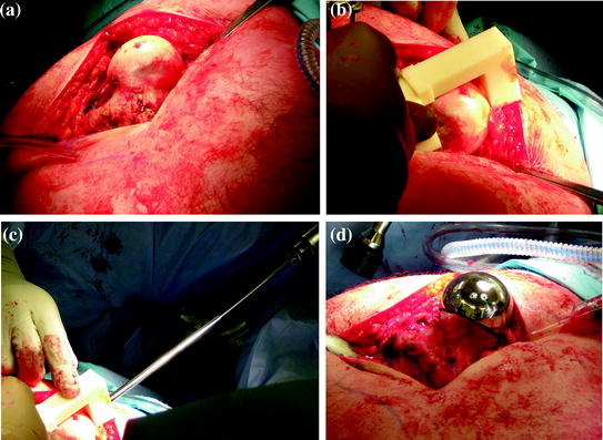
Fig. 5
Intraoperative procedure. a Surgical exposure of the proximal femur. b Registration of the patient-specific guide. c Drilling of the femoral central-pin, navigated by the patient-specific guide. d Final femoral component in place
The surgeon fitted the patient-specific drill guide to the corresponding bone surface at the proximal femur (Fig. 5b) and a conventional metal drill sleeve was inserted into the drill guide channel (Fig. 5c). The central-pin was then drilled using a conventional power drill (Fig. 5d), after which the drill sleeve and the patient-specific guide was removed. In accordance with the conventional procedure, the central-pin was now overdrilled and the guide pin was removed. To measure the achieved central-pin alignment for the purpose of accuracy measurement, we utilized an optoelectronic tracking system (Certus Optotrak, Northern Digital Inc., Waterloo, Canada), with a company reported 3D accuracy of 0.1 mm and a resolution of 0.01 mm. After an optoelectronic marker was attached to the proximal femur, a registration between anatomy and CT model was performed, using a robust method for surface-based registration [60] with reported submillimeter root-mean-square error in the presence of spurious data. After successful registration a tracked pointing device was used to capture the 3D position and orientation of the femoral guide hole (Fig. 6) in the CT coordinate system. After storing this information, the optoelectronic marker was detached from the femur and the remaining steps for the preparation of the proximal femur were performed in the conventional manner. After final preparation and verification, the femoral component was filled with bone cement and impacted into position (Fig. 5, bottom right).
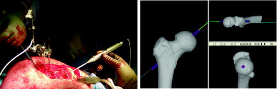
Fig. 6
Accuracy measurement for achieved central-pin alignment. Left side After the attachment of an optoelectronic marker and successful registration a tracked pointing device was aligned inside the central-pin hole. Right Position and orientation of the tracked pointer were stored with respect to the CT coordinate system and deviation between planned and achieved central-pin alignment were determined
2.1.3 Results
The intraoperatively achieved central-pin alignment was 134.1° varus and 7.05° anteversion, only slightly more varus (0.12°) and 3° more anteverted compared to the planned alignment. When comparing the entrance point on the proximal head we found that the final central-pin position was 0.8 mm more distal and 0.2 mm more anterior compared to the planned positioning.
During the final steps of the proximal femur preparation, the surgeon chose to change the planned femoral component size from 54 mm diameter to a 52 mm diameter femoral head.
2.2 Discussion
The application of patient-specific instrument guides for the navigation of femoral central-pin placement during HRA procedures shows promising results in laboratory, in vitro and in vivo studies. So far, all studies that compared outcome between patient-specific guided to conventional methods have shown an increase in accuracy for pin placement using patient-specific instrument guides.
Related posts:
 of Implant Osseointegration by Means of a Reconstruction Algorithm on Micro-computed Tomography Images
Fusion for Computer-Assisted Bone Tumor Surgery
Three-Dimensional Imaging in Fracture Treatment with a Mobile C-Arm
Robotics for Musculoskeletal Surgery
of the Art of Ultrasound-Based Registration in Computer Assisted Orthopedic Interventions
Reconstruction-Based Planning of Total Hip Arthroplasty
of Implant Osseointegration by Means of a Reconstruction Algorithm on Micro-computed Tomography Images
Fusion for Computer-Assisted Bone Tumor Surgery
Three-Dimensional Imaging in Fracture Treatment with a Mobile C-Arm
Robotics for Musculoskeletal Surgery
of the Art of Ultrasound-Based Registration in Computer Assisted Orthopedic Interventions
Reconstruction-Based Planning of Total Hip Arthroplasty
Stay updated, free articles. Join our Telegram channel

Full access? Get Clinical Tree


