Fig. 1
The flexion–adduction internal rotation (FADDIR) (anterior impingement test) test is useful in diagnosing FAI with reproduction of pain in the groin/hip indicating a positive test
The patient is placed in the lateral decubitus position for the next section of the physical exam. This position can aid in the palpation of the greater trochanter, piriformis, abductors, hamstring origin, and tensor fascia lata (TFL). Passive adduction or abduction contractures can be tested, including Ober’s test, along with adduction with the hip in extension, neutral, and flexion. The TFL is tested in extension, the gluteus medius in neutral, and the gluteus maximus in flexion with the shoulders rotated back towards the table. The FADDIR test can be performed in the lateral position as well. The lateral rim impingement is a variation of the posterior rim impingement test, which is performed in the supine position. The hip is brought through a range of passive extension and flexion while the hip is abducted, with reproduction of pain indicating a positive sign. The piriformis test is also performed in the lateral position and involves active abduction and external rotation of the leg against resistance. Finally, extension, abduction, and external rotation of the hip with an anteriorly directed force and reproduction of pain can denote anterior laxity or ligamentum teres injury.
The final portion of the exam is conducted with the patient in the prone position. Femoral anteversion is tested by flexing the knee to 90° and rotating the hip until the greater trochanter is palpated directly lateral, measuring the angle between the tibia and a vertical line. A rectus contracture is tested by flexing the lower extremity towards the gluteus maximus. A restriction of motion or rising of the pelvis is a positive sign.
Imaging
In the diagnostic workup for hip or groin pain, X-rays should be the initial study of choice. In addition to a standard anteroposterior (AP) pelvis view, cross-table lateral, frog-leg lateral, Dunn lateral, false profile, and abduction–internal rotation (ABIR) views can be obtained [16]. The standard AP pelvis is taken with the patient lying supine with the lower extremities internally rotated approximately 15° to adjust for femoral anteversion. The beam should be directed to the midpoint of the symphysis and a line that connects the anterior superior iliac spines (ASIS) (Fig. 2). The cross-table lateral is used to visualize the contours of the femoral head–neck junction. This view is also obtained with the patient supine and the ipsilateral leg internally rotated. The contralateral hip is flexed and the beam is directed towards the inguinal fold at 45°. Alternatives to the cross-table lateral include the frog-leg lateral and the Dunn lateral view (Fig. 3). In order to obtain a frog-leg lateral view, the beam is directed vertically or with a slight (10–15°) cephalic tilt while the patient is supine with the knees flexed, soles of feet together, and thighs maximally abducted. The Dunn view can be obtained at either 45° or 90°. The symptomatic hip is flexed to either 45° or 90°, abducted 20°, and maintained in neutral rotation with the beam directed similar to the AP pelvis at a midpoint between the ASIS and symphysis. The false profile view is performed with the patient standing and the ipsilateral hip against the X-ray cassette and the pelvis rotated 65° in relation to the wall stand (Fig. 4). The ipsilateral foot is parallel to the cassette and the beam centered on the femoral head. The X-ray tube to film distance should be approximately 120 cm for the above studies. The ABIR view is useful to examine congruency when planning a rotational osteotomy about the hip. It is obtained with the patient supine and hips in approximately 20° of abduction and internal rotation.
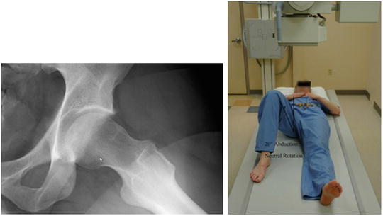
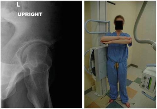
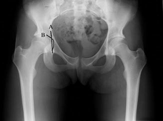
Fig. 2
The standard AP pelvis is taken with the patient lying supine with the lower extremities internally rotated approximately 15° to adjust for femoral anteversion. The beam should be directed to the midpoint of the symphysis and a line that connects the anterior superior iliac spines (ASIS) 120 cm from the patient
Fig. 3
The Dunn view can be obtained at either 45° or 90°. In this example, the symptomatic hip is flexed to 45°, abducted 20°, and maintained in neutral rotation with the beam directed at a midpoint between the ASIS and symphysis
Fig. 4
The false profile view is performed with the patient standing and the ipsilateral hip against the X-ray cassette and the pelvis rotated 65° in relation to the wall stand. The ipsilateral foot is parallel to the cassette and the beam centered on the femoral head
When evaluating imaging of a patient with hip pain or possible acetabular retroversion, there are also several radiographic parameters that need to be determined, including acetabular depth and coverage and congruency of the joint. Acetabular depth is often related to overcoverage or pincer-type FAI. Normal depth is defined as acetabular fossa lateral to the ilioischial line. Coxa profunda (Fig. 5) is defined by the fossa touching or crossing the ilioischial line. Protrusio acetabula (Fig. 6) is defined as the femoral head touching or crossing the ilioischial line. Anterior, lateral, and posterior acetabular coverage are also determined on X-rays. Anterior coverage is examined on the false profile view using the anterior center edge angle (CEA). This angle is formed by a vertical line and a line connecting the center of the femoral head and the anterior portion of the acetabular roof (Fig. 7). Lateral coverage is best determined by the acetabular index, extrusion index and lateral CEA, or center edge angle of Wiberg (Fig. 8). The acetabular index, or acetabular roof angle, is formed by a horizontal line and a line through the medial edge of the sclerotic zone and the lateral edge of the acetabulum (Fig. 9). The extrusion index is the ratio of the uncovered femoral head part to the total femoral head width, with pincer-type FAI having values less than 10 %. The lateral CEA is used to assess superolateral coverage and is formed by a vertical line and a line connecting the center of the femoral head to the lateral portion of the acetabular edge on an AP view. Values greater than 39° are typical in pincer impingement. Posterior coverage is viewed on the AP pelvis view. Reynolds, et al. originally described the crossover sign and the posterior wall sign [1]. The crossover sign was described as a line representing the lateral limit of the anterior wall that lies lateral to a similar point for the posterior wall. With normal anterversion of the acetabulum, on radiographs the anterior wall and posterior wall meet at the sourcil (Fig. 10). The posterior wall sign is present when the visible edge of the outline of the posterior wall descends medial to the center of the femoral head (Fig. 11). The ischial spine sign is also a marker of retroversion, which occurs when the ischial spine projects into the pelvis on an AP view (Fig. 12). It is important to determine the pelvic tilt on the imaging prior to any surgical decision making, as that can affect the version of the acetabulum based on varying degrees of tilt [17, 18]. An increase in the amount of pelvic inclination can show a positive crossover sign in the absence of acetabular retroversion. This pelvic inclination can be determined by measuring the distance between the symphysis pubis and the sacrococcygeal joint, with approximately 3.2 cm for men and 4.7 cm for women [17]. A larger distance indicates more of an inlet view and therefore shows a false increase in anterior coverage. Rotation towards the ipsilateral hip can also cause a false increase in retroversion. Neutral pelvic inclination is approximately 60° and should be standardized when obtaining radiographs to prevent any false appearance of overcoverage or undercoverage [18]. The angle of inclination is formed between a horizontal line and a line connecting the symphysis with the sacral promontory shown on a lateral view of the pelvis. Herniation pits in the femoral neck have also been associated with acetabular retroversion. Ji et al. performed a case–control study compared CT images in asymptomatic and symptomatic patients and found a significant association between herniation pits and central acetabular retroversion and pincer-type FAI [19]. Examination of joint congruity can help differentiate a pincer-type impingement or overcoverage from hip dysplasia . Shenton’s line is formed by the top of the obturator foramen and the inner femoral neck. A break in this line denotes hip subluxation or dislocation. Lateralization of the femoral head based on the position of the medial aspect of the head relative to the ilioischial line also denotes an incongruous joint if greater than 10 mm (Fig. 13). Finally, the centrum collum diaphyseal angle can be measured. This is the angle formed by the femoral head–neck axis and the femoral shaft axis. Normal values are approximately 125–130°, with dysplastic hips having elevated values, and pincer-type FAI hips have decreased values.
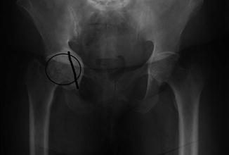
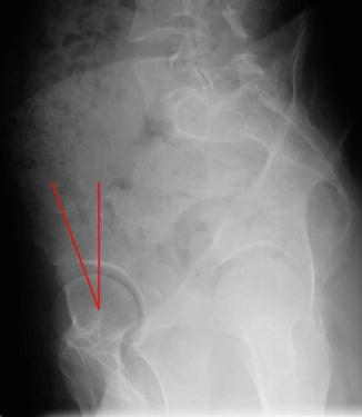
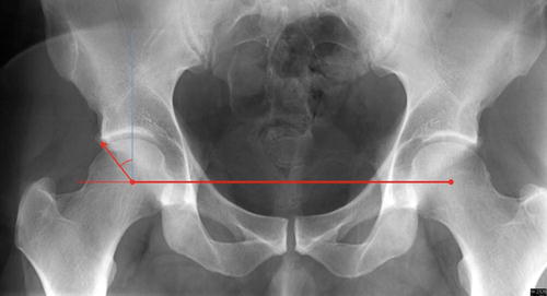
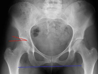
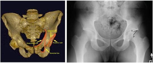
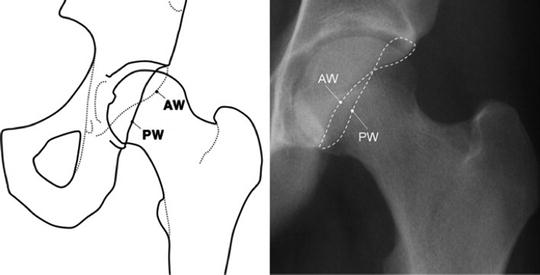
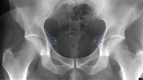
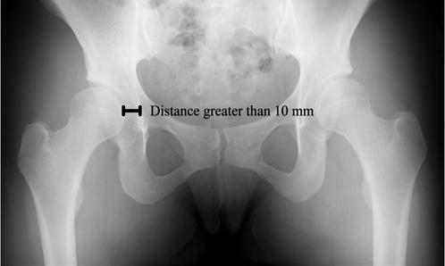
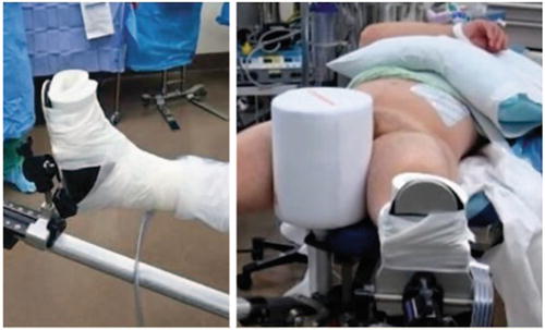
Fig. 5
Coxa profunda is defined by the floor of the acetabular fossa (B) touching or crossing the ilioischial line (A)
Fig. 6
Protrusio acetabula is defined as the femoral head (black circle) touching or crossing the ilioischial line (black line)
Fig. 7
The anterior center edge angle (CEA) is formed by a vertical line and a line connecting the center of the femoral head and the anterior portion of the acetabular roof
Fig. 8
The lateral center edge angle (LCEA) is calculated by creating a horizontal line connecting the center of the two femoral heads. A vertical line (blue line) is then drawn from the center of the femoral head to the acetabulum. A second line (red arrow) is then drawn to the lateral aspect of the sourcil. The angle subtended by these two lines is the LCEA
Fig. 9
The acetabular index, or acetabular roof angle, is formed by a horizontal line (red line parallel to blue line connecting center of femoral heads) and a line through the medial edge of the sclerotic zone and the lateral edge of the sourcil
Fig. 10
Example of pelvic model with normal anteversion of the acetabulum. The posterior wall is lateral to the anterior wall . Radiographs of a normal anteverted acetabulum showing the anterior wall (A) and posterior wall (P) meet at the sourcil
Fig. 11
The posterior wall sign is present when the visible edge of the outline of the posterior wall (PW) descends medial to the center of the femoral head
Fig. 12
The ischial spine sign is a marker of acetabular retroversion, which occurs when the ischial spine projects into the pelvis on an AP view (blue outline)
Fig. 13
Lateralization of the femoral head based on the position of the medial aspect of the head relative to the ilioischial line also denotes an incongruous joint if greater than 10 mm
In addition to radiographs, advanced imaging such as computed tomography (CT) and magnetic resonance imaging (MRI) can also be used to measure version of the acetabulum. Dandachli et al. used three-dimensional (3D) CT scans to determine version of the acetabulum [20]. They compared their results to radiographs and found 92 % sensitivity and 55 % specificity for the crossover sign and 81 % and 53 %, respectively, for the posterior wall sign. Kang et al. performed a similar study but found improved accuracy of radiographs when compared with CT scan, with a 71 % sensitivity and 88 % specificity for detecting retroversion [21]. Two separate methods have also been described for measurement of acetabular version using MRI [22]. Muhamad et al. used compared bony landmark measurements to soft tissue (labrum) measurements to measure acetabular version. They found that acetabular version remained consistent independent of the method used and can provide adequate information for calculating acetabular version.
In summary, there are a wide variety of diagnostic modalities available in the patient with hip pain. Hips with acetabular retroversion can have an increased lateral center edge angle, positive posterior wall sign, positive crossover sign, a positive ischial spine sign, and herniation pits in the femoral neck.
Treatment
Nonoperative management is typically the initial treatment of choice for FAI [23, 24]. These modalities include activity modification, anti-inflammatory medications, and physical therapy. Therapy focuses on range of motion and strengthening of the hip muscles, specifically the hip abductors. Postural and core strengthening exercises can be implemented for those with concomitant lumbar spine pathology. Aquatic therapy can be included to lessen impact on the joints.
Operative treatment is divided into open, mini-open, and arthroscopic approaches. The open approach includes both surgical dislocation for management of FAI and a PAO. The mini-open approach is a combination of arthroscopy and a Hueter approach for osteochondroplasty and can also be used to address acetabular pathology if traction is applied. Arthroscopy allows visualization and management of the entire intra-articular compartment utilizing a minimally invasive approach.
For hip arthroscopy , the patient can be placed into the supine or lateral decubitus position for arthroscopic access to the hip, depending on surgeon preference. A fracture table or one specific for hip arthroscopy can be used. The feet are wrapped in protective boots and placed into foot holders. A well-padded perineal post is placed as well (Fig. 14). Prior to beginning the procedure, the ipsilateral extremity is internally rotated and fluoroscopy is used to determine the appropriate amount of distraction. Venting of the joint is performed using an 18-gauge spinal needle with further traction applied. A minimum of two portals (standard anterolateral and mid-anterior) are used with a capsulotomy performed to allow a diagnostic arthroscopy. Upon completion of the diagnostic arthroscopy and confirmation of acetabular retroversion, acetabular rim trimming can begin (Fig. 15). Similar to open techniques, it may be necessary to detach the labrum prior to rim trimming if resection of more than 3 mm of acetabular rim is planned (Fig. 16) [25]. The capsulolabral junction must be developed and care taken to avoid the reflected head of the rectus. A motorized burr is used to remove bone from the anterosuperior rim. A profile fluoroscopic view can be used to guide the resection. Reattachment of the labrum to the acetabular rim must be performed after completion of acetabular work (Fig. 17). Two to three anchors of surgeon choice (knotless vs. knotted) are used to reattach the labrum with care not to leave the knots on the intra-articular side if using knotted anchors. After the repair is completed, traction can be released and a dynamic examination performed in order to determine the appropriate integrity of the labrum.
 Neuromuscular Hip Disorders: Focus on Cerebral Palsy
 Femoral Deformities: Varus, Valgus, Retroversion, and Anteversion
 Surgical Technique: Arthroscopic Labral Management
 Surgical Technique: Endoscopic Gluteus Medius Repair
 Introduction to Static and Dynamic Overload of Hip Pathology
 Physical Examination of the Hip and Pelvis


Related posts:
Neuromuscular Hip Disorders: Focus on Cerebral Palsy
Femoral Deformities: Varus, Valgus, Retroversion, and Anteversion
Surgical Technique: Arthroscopic Labral Management
Surgical Technique: Endoscopic Gluteus Medius Repair
Introduction to Static and Dynamic Overload of Hip Pathology
Physical Examination of the Hip and Pelvis
Stay updated, free articles. Join our Telegram channel
Full access? Get Clinical Tree
