Fig. 45.1
End-stage degenerative changes and superior migration of the humeral head
We prefer to classify glenoid morphology with the Walch classification [10]. This classification system was validated for its interobserver and intraobserver reliability utilizing a CT scan model, and it allows the surgeon to understand and communicate the shape of the glenoid [11]. Axial glenoid images are examined, and the glenoid version and humeral head posterior subluxation are measured. This is illustrated in Fig. 45.2. The version is measured by the method described by Friedman et al. [12], and this method uses a CT scan along with the plane of the scapula to assess the glenoid. This measurement was also validated in a subsequent CT-based study [13]. These measurements and classifications allow the clinician to assess the glenoid preoperatively, and this allows for preoperative strategies to address significant glenoid retroversion, glenoid bone loss, glenoid shape, and posterior subluxation. Walch [9] has proposed that advanced imaging demonstrating glenoid retroversion of greater than 27° or posterior humeral head subluxation of greater than 80 % is an indication for reverse total shoulder arthroplasty.
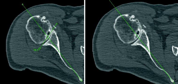
Fig. 45.2
Axial CT images demonstrate measurements for glenoid retroversion and the percentage of posterior humeral head subluxation
MRI and CT evaluation should be combined with clinical exam. Care should be taken to examine the patient for any deficiencies in forward elevation, external rotation/external rotation lag sign, and internal rotation. In addition, the patient must have good deltoid function and no signs of infection. Utilization of MRI data may assist the clinician in further understanding the rotator cuff integrity and presence of atrophy. An MRI demonstrating a superior rotator cuff tear with atrophy is illustrated in Fig. 45.3.
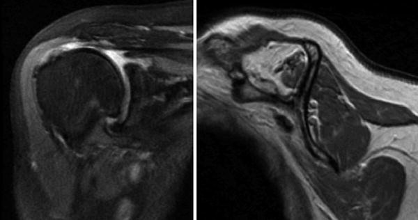
Fig. 45.3
Coronal and sagittal MR images demonstrate a tear of the superior rotator cuff with retraction and atrophy. The posterior rotator cuff has minimal atrophy
Surgical Technique
For the approach, a straight line incision is made from the lateral edge of the coracoid process distally to the deltoid insertion. The cephalic vein can be taken medially or laterally. Taking the vein medially may allow less forceful retraction and greater ease in protecting the vein with retractors. The clavi-pectoral fascia is identified and incised along the lateral aspect of the coracobrachialis. A release of the upper reflection of the pectoralis may be helpful, but our preference is to maintain the integrity of the pectoralis tendon. Next identification of the axillary nerve is performed using the musculotendinous junction of the subscapularis as a palpation reference point. The biceps groove is identified and opened, and the biceps is followed up to the rotator interval. Release of the rotator interval allows for a tenotomy of the biceps from the supraglenoid tubercle. A non-absorbable suture is then utilized to tenodese the biceps to the upper border of the pectoralis major tendon. This may be done at the beginning or the end of the procedure. Next, identification of the circumflex humeral artery and surrounding veins is performed. The artery and veins are carefully dissected and tied off. Delineation of the inferior and superior border of the subscapularis is then completed. Release of the subscapularis may be performed via an osteotomy, peel, or tenotomy. Our preference is to utilize a tenotomy at the medial edge of the biceps groove. This technique improves ease of reapproximation with the distalization of the insertion point occurring with reverse total shoulder arthroplasty. Non-absorbable suture is used to tag the subscapularis, and the humerus is rotated as the inferior capsule is released to allow dislocation.
Careful adduction and external rotation allow for humeral head dislocation. Retractors are placed anterior to protect the axillary nerve and cephalic vein, posteriorly to retract soft tissue and superiorly to assist in clearance of the humeral head. The starting reamer is placed just medial and posterior to the biceps groove. This position typically coincides with the most superior portion of the humeral head. Reaming continues by hand at 1 mm increasing increments until cortical contact is made. Each reamer must be reamed to the appropriate depth for stem length. The trabecular metal stems come in even increments from 8 to 18 mm at the 130 mm length, and even increments 8–16 mm in available in the 170 mm length. If a non-coated stem is preferred, the surgeon has the choice of size 6 mm and sizes 8–16 mm in one millimeter increments at the 130 mm length and even increment sizes 8–16 mm in the 200 mm length.
Sizing of the humeral stem requires consideration proximally and distally. The stem has a 4° taper proximally extending to the midshaft, and a 1° taper is present at the far distal end. The initial reamers determine the distal fit. This will typically leave around 0.5 mm of clearance distally. If cementing the prosthesis, we suggest downsizing one millimeter in size from the final distal reamer size. Choosing the same size proximal reamer will give a +0.5 mm press fit around the trabecular metal portion.
Preparation of the proximal humerus begins by leaving the final distal reamer in place. Osteophytes are removed with a rongeur to allow for accurate visualization of the humeral head. A cutting guide is placed in 0°–20° of retroversion, depending on surgeon preference. Alignment rods may be utilized in relation to the long axis of the forearm for version guidance. Once the cutting guide is pinned into place and reamer removed, the cut is made with an oscillating saw. Cutting is recommended along the superior aspect of the guide first, not through the slots. After the cutting guide is removed, there are two proximal reamers. Both reamers are hand-driven. The first reamer will dilate proximally. Then a distal guide (pilot), the size or just smaller than the last distal reamer, is chosen and a proximal conical reamer in a size that matches the chosen stem size is obtained. The pilot is attached to the conical reamer, and the proximal humerus is reamed by hand with care to match the angle of the cut. Reaming continues to a depth where the conical reamer is flush with the cut surface. The trial stem is impacted into place. The stem can be reduced with only the trial and trial spacer in place. The trial spacer should sit at approximately the midpoint of the glenoid. If the trial sits higher than this, more soft tissue release may be needed during the glenoid exposure. The trial stem is left in to assist in protecting the proximal humerus during glenoid preparation. Preparation of the proximal humerus is demonstrated in Fig. 45.4.
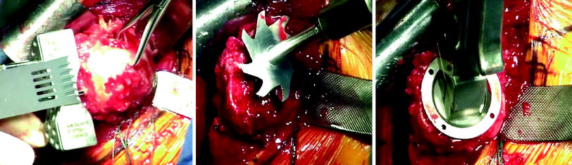
Fig. 45.4
From left to right Cutting of the proximal humerus along the cutting guide, using the conical reamer to prepare the proximal humerus and impacting the trial stem
Glenoid exposure begins with a 360° subscapularis release from the anterior capsule and coracohumeral ligament. Anterior and posterior glenoid retractors are placed, and a complete labral excision is performed. Using care to protect the axillary nerve, the inferior capsule is completely released. It is often necessary to release a portion of the triceps origin along the inferior glenoid. A curette or a glenoid scraper should be used to remove any remaining cartilage from the glenoid surface. Then with a comparison of preoperative imaging and palpation along the anterior glenoid, the version and necessary correction should be determined. A baseplate drill guide is sized along the glenoid. The outer edge of the drill guide is the same diameter as the baseplate and thus, the guide should be placed flush with a well-visualized inferior glenoid bony rim. The guide center should be centered anterior to posterior on the glenoid, and a guide pin is placed. This is illustrated in Fig. 45.5. A slight inferior tilt is desirable.
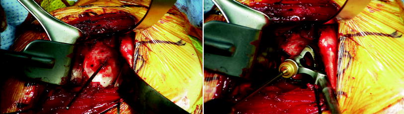
Fig. 45.5
Glenoid guide pin is placed on the left. Right illustrates the glenoid guide siting flush along the inferior glenoid rim positioned in the center relative to the anterior and posterior glenoid
Before continuing, the guide pin placement should be inspected. Any variance from the desired position should be corrected. A cannulated drill then is placed over the guide wire and drilled to the desired central post length. For most primary reverse cases not requiring bone grafting or significant version correction, a 15-mm central post can be implanted. After drilling the central hole, both the drill and the guide pin are removed. Palpation into the hole should be done to understand if there was penetration of the glenoid vault. Glenoid reaming is then carefully done by hand without excessive force to avoid excessive reaming or fracture. Reaming is continued until the surface is completely flush with subchondral bone exposed inferiorly. The second reamer should be chosen for either a 36- or 40-mm baseplate. The purpose of the second reamer is to ream away surrounding bone to give clearance to the glenosphere to completely seat flush on the baseplate. Occasionally, the outer diameter of the second reamer prevents it from being utilized in a tight exposure. In that occasion, a rongeur or a burr should be used to clear away surrounding bone. Finally, the center post hole is enlarged with a final drill to the appropriate depth of the baseplate central peg.
Related posts:
 Biomechanics of the Reverse Total Shoulder Replacement: The Hospital for Special Surgery Perspective
 Analysis of Reverse Total Shoulder Arthroplasty Biomechanics Using a Dynamic Shoulder Simulator
 Exactech Equinoxe RTSA Platform Shoulder System Design Rationale
 Influence of Arm Lengthening in Reverse Shoulder Arthroplasty
 2 Reverse Total Shoulder Arthroplasty: Biomechanics and Design Challenges
 18 Infection after Reverse Shoulder Arthroplasty: Workup, Diagnosis, and Treatment
Stay updated, free articles. Join our Telegram channel

Full access? Get Clinical Tree


