X-Ray Equipment, Alignment, and Patient Safety
Roderic P. Rochester
Learning Objectives
After completing this chapter, students should be able to:
Include information in a sales agreement that will meet the standards required for practicing the Orthospinology procedure.
Describe the specifications of the necessary X-ray equipment, including generator capacity, tube column height, grid line ratio, tube Focal spot marking, Collimation, tube housing specifications, screens, blockers, markers, and digital computer-assisted radiography.
List the procedures required to align the X-ray equipment to the specifications required to practice the Orthospinology procedure, including basic alignment procedures, laser alignment, installing a string guide, marking the grid cabinet, and the final alignment test.
Describe the X-ray developing process and the double-marking system.
Discuss the reasons for the alignment requirements of X-ray equipment, including Projection distortion and contrast.
Discuss the meaning of the ALARA (as low as reasonably achievable) philosophy and the steps required to minimize radiation exposure to the patient.
X-ray Equipment Capacity and Specifications
The Orthospinology procedure is one of only a few techniques within the chiropractic profession that attempts to quantify the misalignment component of the upper cervical Subluxation complex. To do this as reliably and accurately as possible, the equipment used for imaging the upper cervical spine must be aligned properly to minimize distortion. This chapter will explain the detailed process of selecting and aligning appropriate X-ray equipment. The procedures and equipment necessary to minimize radiographic exposure to the patient is reviewed as well. It is also necessary to remember to keep radiation exposure to as low as reasonably achievable (ALARA).
The basic equipment required for radiographic imaging in an Orthospinology practice includes:
X-ray generator
Tilting grid cabinet that will achieve at least 60° from vertical
Tube column capable of reaching 84 inches of tube height
Collimator
Wall stand
X-ray tube
The most common generator is the 300 milliamperes (mA)/125 kilovolts peak (kVp). Other models to choose from would be 400 mA/125 kVp, 500 mA/150 kVp, and 600 mA/150 kVp. With the advent of high-frequency generators, the radiographic process has become much more reliable and reduces radiation exposure to the patient by up to 50%. The 300 mA/125 kVp is usually sufficient for a private practice.
Special X-ray accessories are necessary to practice upper cervical chiropractic based on the Grostic model and to align the X-ray equipment. Some of the accessories that will be needed are:
Alignment rod
Turntable chair
Wood or Plexiglas alignment block with lead crosshairs
Beaded chain
Straight rod about the size of a bicycle spoke
These items will be used in the alignment process. An L-frame or double L-frame is very beneficial and is recommended, but it is not an absolute requirement. Alignment of the X-ray equipment reduces radiation to the patient, minimizes distortion, and improves image contrast. This chapter will outline the steps necessary for self-installation, but some X-ray companies—like American X-ray Corporation in Knoxville, Tennessee—use a laser alignment method that can save the new practitioner many hours of Work setting up the appropriate equipment.
When choosing an automatic processor, be sure to check for quality as well as price. It behooves the doctor to find a high-quality X-ray processor, change the chemicals frequently, and have a scheduled regimen for cleaning it. It is normal to have the processor cleaned at least every 60 days; however, chemicals should be changed at least every 30 days. Increasing radiation to the patient because the X-ray processor chemicals are weak is not appropriate. The Orthospinology procedure requires reliable identification of specific osseous landmarks, which demands a high-quality imaging process while complying with the ALARA philosophy.
Designing the X-ray room is a very important step for the new practitioner. Nine-foot ceilings are preferable. A 14- to 15-foot horizontal wall space is minimal to achieve a 72-inch Focal film distance (FFD), place the transformer, and attach the wall mount for the grid cabinet. Lead shielding in the walls is required for an X-ray room, but the doctors should check with their own state regulations. It is recommended to have a radiation physicist do a “plan and review” to meet the specific state requirements. Note: Be careful in purchasing used equipment. Make certain it conforms to state and federal radiation control laws. If in doubt, check with State Department of Public Health, Division of Radiological Health.
Equipment Alignment Process
Mounting research indicates that the upper cervical Subluxation complex is a clinical entity that has a measurable osseous component. The atlas vertebra subluxates around the occipital condyles to the right or the left of a Hypothetical normal. It can rotate beneath the skull on the side of lateral Subluxation in either the anterior or posterior direction. Chiropractors need to be able to determine the direction and magnitude of relative alignment in the upper cervical spine. The radiographic process creates a shadow of a three-dimensional object, compressing it into two dimensions, and much information is lost. This necessitates the need for proper X-ray equipment alignment. The chiropractor needs to be able to reliably detect changes in upper cervical alignment of approximately 3/4°. That is slightly less than 1 millimeter in Linear measurement. When purchasing the X-ray equipment, make it immediately known that payment will not be made for equipment that does not conform to the Orthospinology standards. Put it in the sales contract before making a down payment. Having equipment that does not meet minimum standards will inhibit the doctor from measuring relative vertebral alignment with any degree of Validity.
The very first step in the Orthospinology procedure is to align the X-ray equipment. When having someone do a build out in a leased office space or when building an office, make sure that the walls in the X-ray room are at perfect 90° angles and plumb. With the introduction of the L-frame, this requirement is not as important. If an L-frame is not used, the accurate construction of the X-ray room walls will save a great deal of time in the future.
Ceiling Track and Floor Track for Tube Stand
Using a chalk line, construct a straight line on the ceiling that is parallel to the wall. Set the ceiling tracks about 10 inches from the wall, and anchor the ceiling tract to the overhead joists, being sure it is straight along the line and perfectly horizontal. Shims may be required to achieve this step. If the joists are parallel to the tracts, anchor a plate to the joists, and attach the ceiling track to the plate. Place the floor track under the ceiling track, and place the tube stand into the ceiling track and on the floor track. Adjust the floor track so the tube stand is exactly vertical as it runs the full length back and forth on the track. Shim the floor track so it is level along its full length. Attach the track to the bare floor not the carpet.
Wall Frame, Grid Carrier, and Grid Cabinet
The grid cabinet must be Perpendicular to the track as it travels up and down. First mount the grid cabinet on the grid carrier, and make sure that it is horizontal when the wall frame is exactly vertical. To be sure the wall frame is connected to the wall studs on both sides, attach a wood plate to the studs with lag screws, then attach the wall frame to the plate. Construct a line at 90° to the track on the floor. Use a large metal square that is accurate and extend the line or strike arcs and erect a Perpendicular line to the tracks. Hang three plumb bobs with one over each end and one in the center. The plate or frame can be shimmed to bring the wall frame and grid cabinet to 90° in the full range of movement. Anchor
the wall frame into the wood plate at the top and into the floor at the bottom (Figs. 2-1 and 2-2).
the wall frame into the wood plate at the top and into the floor at the bottom (Figs. 2-1 and 2-2).
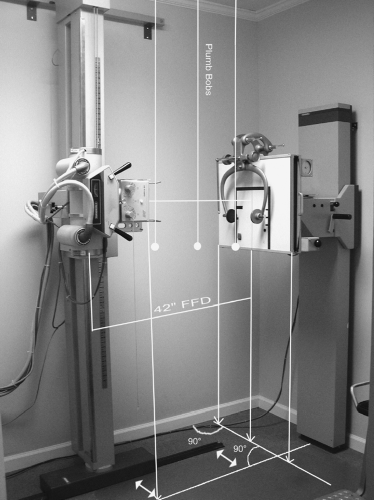 FIGURE 2-1 X-ray equipment alignment. |
Bucky or Grid
Orthospinology recommends a 14′ × 17′ or 10′ × 12′ 103-line grid with a 10:1 or 12:1 grid ratio. Traditionally, 8′ × 10′ films have been used in an upper cervical practice and are acceptable. However, 10′ × 12′ film allows more of the skull and neck to be visible for lateral, nasium, and vertex views. A 14′ × 17′ grid is advisable to be able to take low-back and thoracic X-rays. A special wire grid is imbedded in the grid cabinet, and it is recommended that it should have at least a 10:1 ratio with a minimum of 103 lines per inch for plane film radiography. However, with newer computer-assisted radiography (CR), 178 lines per inch is optimal. Grids can be purchased that are focused from 40 to 72 inches. The FFD has been traditionally set at 42. Screens and film should be fast to reduce radiation to the patient. Rare-earth screens equivalent to at least 400 speed will provide adequate detail and reduce exposure to ionizing radiation. A stationary grid is recommended over a moveable bucky.
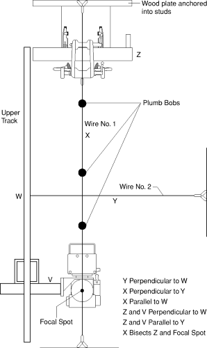 FIGURE 2-2 X-ray equipment alignment, top view. |
Tube Arm
The tube carrier arm must be at 90° to the track. Check this by dropping at least two plumb bobs over the tube arm to a line on the floor that is at 90° to the track. The tube arm must remain horizontal when supporting the weight of the tube, and this should be verified with a level. If there is not a way to bring the tube arm to the necessary 90° position, the equipment should not be purchased. The tube arm must also be adjustable in and out to align the Focal spot to the center of the grid.
Tube
The tube must be parallel to the face of the grid. With the collimator removed, bring the tube up to the face of the
grid. Anchor the tube parallel with the face of the grid. When the basic alignment is completed it should match Figure 2-1 and Figure 2-2 and be well anchored.
grid. Anchor the tube parallel with the face of the grid. When the basic alignment is completed it should match Figure 2-1 and Figure 2-2 and be well anchored.
 |
Focal Spot
Note that it is required to align the Focal spot in the tube with the vertical centerline of the grid before checking the head clamp and alignment rod for precise alignment. To find the center of the Focal spot or Central ray, cut a piece of lead the size of the port opening. Mark the lead piece in three different areas, making sure to extend the marks onto the tube housing. This will allow the lead piece to be replaced in the exact location on the tube housing. Pierce a hole in the center of the lead the size of a pencil point. The center of the lead piece can be found by scribing arcs on the lead. Replace the lead piece onto the tube housing, and tape it in the exact position by lining up the marks made previously. Hang a beaded chain with a weight directly over the vertical centerline on the grid cabinet. Move the tube as close as possible to the grid cabinet, with the tube being the same height as the horizontal line on the grid cabinet. When loading a film into the cassette for the test, be sure to punch a hole in the film to indicate the right side of the film. Reduce the kVp to about 30 using 10 mA, and expose the film for 1/10 second.
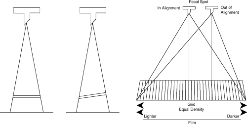
The dark spot should appear in the center of the film with the beaded chain bisecting it. If the beaded chain appears in the center, bisecting the dark spot, then mark the center of the Focal spot on the tube housing. Should the chain not be in the center, use the hole in the film that was placed on the right side to determine which direction to move laterally on the piece of lead to place another hole and retest. Once the center of the Focal spot has been identified, move the tube out to 42 inches and expose another film, keeping the tube at a constant height from the floor. The beaded chain should bisect the dark spot. One reason the Central ray must be centered to the center of the film and the center of the grid is to use the grid most efficiently. The grid is focused to a certain FFD, so when the Central ray is in the exact center at the proper FFD, the density of mA exposure will be the greatest with the least amount of mA exposure to the patient. If it is not centered, the density will also be uneven on the film: lighter on one side and darker on the other (Fig. 2-3).
Laser Alignment with L-frame
American X-ray Corporation uses the following protocol during the laser alignment of their L-frame system. The laser alignment process begins with the manufacturing of the L-frame. The unit is constructed with very small tolerances for error so that subsequent alignment of the X-ray equipment is accurate and reliable. Once the equipment is delivered to the clinic, the laser alignment process continues. The technicians take extra steps to insure the equipment can be aligned perfectly. A digital level accurate to less than 1/10° enables the construction from the ground up, ensuring every piece is level and
square. Once the frame is constructed, the laser is placed in a special holder, which enables it to be guided through the center porthole of the tube mount, reproducing the Central ray of the X-ray beam. Lead counterweights are used on the tube mount to simulate the tube and collimator weight.
square. Once the frame is constructed, the laser is placed in a special holder, which enables it to be guided through the center porthole of the tube mount, reproducing the Central ray of the X-ray beam. Lead counterweights are used on the tube mount to simulate the tube and collimator weight.
Related posts:


Stay updated, free articles. Join our Telegram channel

Full access? Get Clinical Tree


