The shoulder is the most common region to be evaluated with musculoskeletal ultrasound. The shoulder’s complex anatomy enables an exceptional range of mobility at the expense of static stability. Consequently, the shoulder is susceptible to a multitude of traumatic and atraumatic injuries. This article presents an overview of shoulder anatomy, recommends a standardized approach to the sonographic shoulder evaluation, and discusses common sonographically apparent pathology of the shoulder.
The shoulder complex is susceptible to a multitude of traumatic and atraumatic disorders. Owing to the relatively superficial location of many shoulder structures, ultrasound (US) is a commonly used imaging modality for the evaluation of shoulder pathology and the guidance of interventional procedures about the shoulder region. The first consistent application of diagnostic US was for the evaluation of shoulder soft tissue structures, such as the rotator cuff. However, the shoulder is a technically difficult region to evaluate sonographically because of the curved nature of many shoulder structures, thus increasing their susceptibility to anisotropic artifact. Consequently, impeccable scanning technique is essential to maximize the diagnostic sensitivity and specificity of shoulder US. In addition, not all shoulder structures are amenable to a complete sonographic evaluation, such as the glenoid labrum and intra-articular structures. The limitations of US need to be recognized and appropriate alternative imaging modalities, such as standard radiographs or magnetic resonance imaging, should be used when appropriate. This article reviews sonographically relevant shoulder anatomy, presents a systematic approach to the diagnostic US examination of the shoulder, and discusses common sonographically apparent shoulder pathology.
Shoulder anatomy
Acromioclavicular Joint
The articulation between the hyaline-covered ends of the lateral clavicle and medial acromion is termed the acromioclavicular joint (ACJ). The ACJ also contains a fibrocartilaginous disk, which either partially or fully separates the joint into synovial-lined medial and lateral joint cavities. The ACJ is stabilized by the superior ACJ ligament; the inferior ACJ ligament, which receives some fibers from the coracoacromial ligament; and the medially located coracoclavicular ligament, which limits upward displacement of the clavicle.
Glenohumeral Joint
The large, round humeral head articulates with the relatively flat glenoid fossa forming the glenohumeral joint. Because of the relative incongruence between these two joint surfaces, the glenohumeral joint is prone to instability. The articular surfaces of the humeral head and glenoid fossa are both covered by hyaline cartilage. The hyaline cartilage of the humeral head extends laterally to the anatomic neck of the humerus. A triangular fibrocartilage labrum attaches to the peripheral margin of the glenoid, thus increasing the depth and width of the glenoid fossa and increasing the static stability of the glenohumeral joint. The glenohumeral joint capsule has several joint recesses including the tendon sheath of the long head of the biceps brachii tendon, the axillary recess, and the subscapular recess, which usually arises between the superior and middle glenohumeral ligaments, and extends over the top of the subscapularis tendon like a “saddle.”
Muscles and Subacromial-Subdeltoid Bursa
The rotator cuff is composed of 4 muscles: the subscapularis, supraspinatus, infraspinatus, and teres minor muscles. The subscapularis muscle arises from the subscapularis fossa on the anterior surface of the scapular body, and gives rise to 2 or 3 intramuscular tendons as it progresses in a cephalolateral direction. The multiple intramuscular tendons eventually coalesce into one common tendon, which has a broad insertion onto the lesser tuberosity of the humerus. Some of the more superficial fibers of the subscapularis tendon extend across the bicipital groove and assist in forming the transverse humeral ligament, which stabilizes the long head of the biceps brachii muscle in the bicipital groove. The cephalad fibers of the subscapularis tendon are intra-articular, whereas the caudal fibers of the subscapularis tendon are extra-articular.
The supraspinatus muscle originates from the supraspinous fossa of the scapular body and can be divided into 2 distinct portions: the ventral portion, which arises from the anterior region of the supraspinous fossa, and the dorsal portion, which arises from the posterior region of the supraspinous fossa. The supraspinatus muscle extends laterally beneath the acromion and above the glenohumeral joint and inserts onto the greater tuberosity’s superior facet and the anterior portion of the middle facet. Occasionally, some fibers from the ventral portion of the supraspinatus tendon insert onto the lesser tuberosity, thus contributing to the stability of the long head of the biceps brachii tendon. The 2 portions of the supraspinatus tendon have different sonographic appearances, with the ventral portion having more of an oval shape and the dorsal portion a more flat shape. This leads to dissimilar mechanical properties, which can lead to shear stresses between them. The supraspinatus tendon footprint on the greater tuberosity is approximately 2.25 cm in anterior to posterior (ie, transverse) length. However, only the anterior 1.5 cm of the supraspinatus tendon are strictly composed of supraspinatus fibers. The remaining posterior portion of the supraspinatus tendon overlaps with the anterior fibers of the infraspinatus tendon as described in the next paragraph.
The infraspinatus muscle arises from the scapular body’s infraspinous fossa and forms a wide tendon as it extends in a cephalolateral direction, eventually inserting onto the posterior portion of the greater tuberosity’s middle facet. The posterior portion of the supraspinatus tendon and the anterior portion of the infraspinatus tendon overlap and coalesce near their insertion on the greater tuberosity. The beginning of this overlap is approximately 1.5 cm posterior to the anterior margin of the supraspinatus as measured in a transverse plane. The supraspinatus-infraspinatus overlap ends and the independent infraspinatus tendon begins approximately 2.0 to 2.5 cm posterior to the anterior margin of the supraspinatus as measured in a transverse plane.
The final muscle of the rotator cuff, the teres minor, arises from the inferolateral border of the scapular body, and forms into a narrow tendon as it progresses cephalolaterally to its insertion on the greater tuberosity’s inferior facet.
Between the cephalad margin of the subscapularis tendon and the anterior margin of the supraspinatus tendon lies the rotator cuff interval, which contains the long head of the biceps brachii tendon, the superior glenohumeral ligament, and the coracohumeral ligament. As previously described, the long head of the biceps brachii tendon has a tendon sheath, which is a direct extension of the glenohumeral joint capsule. This tendon sheath extends approximately 3 to 4 cm distal to the intertubercular groove. The ascending branch of the anterior humeral circumflex artery lies lateral to the long head of the biceps brachii tendon in the intertubercular groove. Proximal to the intertubercular groove in the region of the rotator interval, the long head of the biceps brachii tendon is stabilized by the reflection pulley, which is a fibrous sling formed by the coracohumeral ligament and superior glenohumeral ligament that wraps around the anterior aspect of the long head of the biceps brachii tendon. As previously mentioned, the transverse humeral ligament stabilizes the long head of the biceps brachii tendon within the intertubercular groove. The transverse humeral ligament is created by a combination of fibers from the coracohumeral ligament, and the subscapularis and supraspinatus tendons.
The deltoid muscle lies superficial to the rotator cuff tendons, rotator cuff interval, and the glenohumeral joint. It has a wide origin from the spine of the scapula, acromion, and lateral clavicle, and extends distally to insert onto the deltoid tubercle of the humerus.
The subacromial-subdeltoid bursa (SASD) lies deep to the deltoid muscle as well as the acromion and the coracoacromial ligament, and superficial to the supraspinatus tendon, rotator cuff interval, greater tuberosity, and intertubercular groove. The SASD’s posterior margin is highly variable. Laterally, the SASD usually extends approximately 3 cm below the greater tuberosity. The SASD is surrounded by a thin layer of peri-bursal fat, which assists in the bursa’s main function of facilitating gliding between the rotator cuff tendons and the coracoacromial arch and deltoid muscle during shoulder movements.
Neurovascular Structures
The suprascapular nerve originates from the upper trunk of the brachial plexus and travels with the suprascapular vessels through a tunnel formed by the suprascapular notch and superior transverse scapular ligament, and arrives in the supraspinous fossa where it innervates the supraspinatus muscle. The infraspinatus branch of the suprascapular nerve exits the supraspinous fossa in an inferolateral direction, enters a tunnel formed by the spinoglenoid notch and the inferior transverse scapular ligament, and arrives in the infraspinous fossa where it innervates the infraspinatus muscle.
Ultrasound examination of the shoulder
For the US examination of the shoulder, a linear array transducer with a frequency of at least 10 MHz is typically used, although lower frequencies may be required to adequately image deeper structures in patients with a large body habitus. Although the US examination of many joints can be focused to one region of the joint, the shoulder US examination should be comprehensive because of the limited ability to localize shoulder pathology with a history and physical examination. Appropriate positioning of the patient is imperative to improve patient and physician comfort, and to ensure efficient access to all regions of the shoulder. We recommend placing the patient in a seated position on a stool that allows for rotation of the patient. The examiner should either stand during the examination or sit on a stool with wheels to facilitate mobility. A systematic approach to the examination should be followed to ensure all relevant structures have been evaluated ( Table 1 ). If indicated, an additional targeted examination can be performed following the comprehensive evaluation. Key anatomic areas and areas of pathology should be imaged in 2 orthogonal planes. The contralateral shoulder can be used for comparison, but one should remember that it is possible to have concomitant pathology in bilateral shoulders. Each image should be optimized by adjusting the image depth, focal zones, gain, and time-gain compensation. Power-Doppler or color-Doppler imaging should be used when indicated. Dynamic evaluations of the long head of the biceps brachii tendon for instability and the SASD for impingement should be performed. The following section describes each component of the shoulder US examination.
| Static Evaluation | Dynamic Evaluation |
|---|---|
|
|
Long Head of the Biceps Brachii Tendon
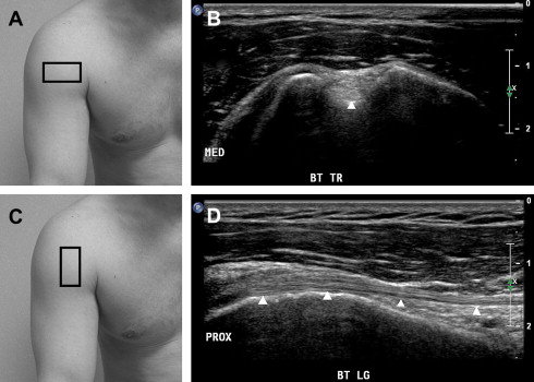
The patient’s hand should be placed palm up (ie, supinated) on his or her ipsilateral knee. The US probe should be placed over the anterior proximal humerus to obtain a transverse image of the long head of the biceps brachii tendon ( Fig. 1 ). The tendon should be scanned from distal to proximal, beginning at its musculotendinous junction, which is located approximately at the level where the pectoralis major tendon crosses superficial to the long head of the biceps brachii tendon. The transducer should be glided proximally to the intertubercular groove, where the depth and width of the groove and presence or absence of cortical irregularities should be noted. An intertubercular groove depth of 3 mm or less may predispose to instability of the long head of the biceps brachii tendon. The tendon should have a round shape and hyperechoic fibrillar appearance at this level (see Fig. 1 ). The presence of a small amount of fluid that does not completely surround the tendon within the long head of the biceps brachii tendon sheath is considered physiologic. The tendon should be followed proximally with the transducer to image its intra-articular portion, where it assumes a more oval shape, but maintains its relatively hyperechoic fibrillar appearance. The ultrasonographer should remember to “wag” the transducer as the long head of the biceps brachii tendon wraps around the top of the humerus and enters the joint to minimize anisotropy. The tendon should then be imaged longitudinally by turning the US transducer 90 degrees and following the tendon distally to its musculotendinous junction (see Fig. 1 ). Anisotropy while scanning the long head of the biceps brachii tendon longitudinally can be reduced by performing a heel-toe maneuver in which the distal end of the transducer is compressed into the soft tissues of the shoulder.
A dynamic evaluation of the long head of the biceps brachii tendon stability can be performed by returning the US transducer to its original transverse position over the tendon at the level of the intertubercular groove. The patient should be instructed to externally and internally rotate the shoulder while the examiner monitors for subluxation or dislocation of the long head of the biceps brachii tendon out of the intertubercular groove.
Subscapularis Tendon
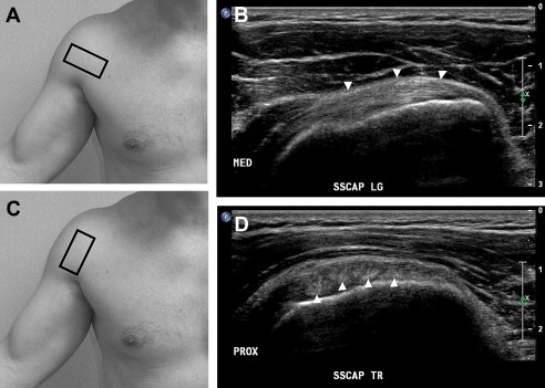
After performing the dynamic stability evaluation of the long head of the biceps brachii tendon, the patient should be instructed to maintain his or her shoulder in an externally rotated position. The US transducer, which had been monitoring the long head of the biceps brachii tendon in a transverse view, is glided medially over the lesser tuberosity to image the subscapularis tendon in a longitudinal view ( Fig. 2 ). The US transducer should be glided proximally and distally along the lesser tuberosity to ensure complete visualization of the subscapularis tendon in a longitudinal view. The transducer should then be rotated 90 degrees and the subscapularis tendon should be imaged in a transverse view from its lateral insertion on the lesser tuberosity to its medial musculotendinous junction (see Fig. 2 ). Several hypoechoic regions of muscle can often be visualized between hyperechoic, fibrillar tendon bundles near the insertion of the subscapularis tendon on the lesser tuberosity, and should not be mistaken for tendon pathology.
Acromioclavicular Joint
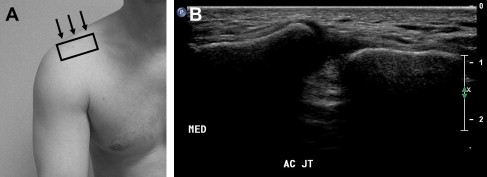
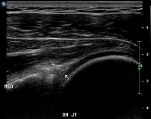
The ACJ should be located via palpation. The examiner should then place the transducer over the ACJ in an anatomic coronal-oblique plane ( Fig. 3 ). The hyperechoic ends of the clavicle and acromion bones will be identified with the interposing ACJ space (see Fig. 3 ). The transducer should be glided anteriorly and posteriorly over the joint to provide a thorough evaluation for pathology. Maneuvers to promote widening of the ACJ, such as axial traction of the arm, can be performed if a sprain to this joint is suspected.
Posterior Shoulder
The spine of the scapula should be palpated by the examiner. The transducer should be placed over the middle of the scapular spine in an anatomic sagittal plane and glided inferiorly to visualize the infraspinatus and teres minor muscles in a transverse view ( Fig. 4 ). The infraspinatus muscle is located superior to the teres minor muscle, and is normally approximately 70% to 100% larger than the teres minor. A loss of muscle volume combined with a relative increase in muscular echogenicity suggests muscle atrophy, which may be indicative of a large rotator cuff tear or denervation. The hyperechoic fibrillar pattern of the tendons should be visualized within their respective hypoechoic muscles. The transducer should be glided laterally to follow the infraspinatus and teres minor tendons to their insertions on the middle and inferior facets of the greater tuberosity, respectively. The transducer should then be moved back to its starting position and a transverse view of the infraspinatus muscle and tendon should be reacquired. The transducer should then be slowly rotated 90 degrees to provide a longitudinal view of the infraspinatus tendon (see Fig. 4 ). The transducer should be glided laterally to image the entire infraspinatus tendon to its distal insertion on the greater tuberosity. The same procedure can be followed to image the teres minor tendon in a longitudinal view. However, because of the oblique course of the teres minor tendon, the transducer will be oriented in an anatomic sagittal oblique axis in which the lateral aspect of the transducer is slightly cephalad relative to the medial aspect of the transducer.
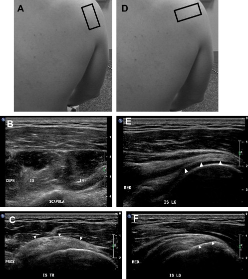
After visualizing the infraspinatus and teres minor muscles and tendons, the transducer should be placed back over the infraspinatus tendon, and a longitudinal image of this tendon should be acquired. The depth of the US image should be adjusted such so that the underlying glenohumeral joint is visualized ( Fig. 5 ). The transducer should be glided cephalad and caudad to ensure complete visualization of the posterior glenohumeral joint and the posterior glenoid labrum. As the transducer is glided toward the cephalad margin of the posterior glenohumeral joint, the spinoglenoid notch may be visualized medial to the glenohumeral joint.
Lateral Shoulder
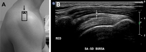
The transducer should then be moved to the lateral shoulder, and placed in the scapular (coronal oblique) plane with the proximal aspect of the transducer imaging the lateral aspect of the acromion process, and the remaining footprint of the transducer imaging the deltoid, SASD, and portions of the infraspinatus and/or supraspinatus tendons ( Fig. 6 ). The transducer should be glided anteriorly, posteriorly, and caudally to evaluate the entire subacromial region. The transducer should then be moved back to its starting position and the patient should be asked to abduct the shoulder. Normally, the rotator cuff muscles and greater tuberosity should move smoothly underneath the lateral acromion process, and no fluid should be “milked” into the SASD. This is called the subacromial impingement test.
Supraspinatus Tendon
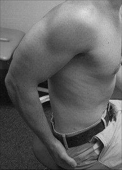
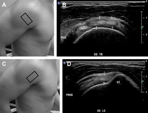
The patient should be asked to place his or her hand on his or her back pocket with the palm facing toward the buttock. The patient’s elbow should be positioned such that it lies within the anatomic sagittal plane and care should be taken to minimize the patient’s natural inclination to allow the elbow to drift into a coronal oblique plane ( Fig. 7 ). This position, called the modified Crass position, optimizes the ability to image the supraspinatus tendon. The transducer should be placed transversely over the biceps tendon in the bicipital groove ( Fig. 8 ). The transducer should be glided proximally over the biceps tendon until it exits the bicipital groove. At this level, the distal anterior margin of the supraspinatus tendon will be visualized lying posterior to the biceps tendon (see Fig. 8 ). The transducer should be glided proximally while maintaining an image of the biceps tendon and anterior margin of the supraspinatus tendon until the entire anterior margin of the supraspinatus tendon has been imaged. The transducer should then be moved posteriorly and glided proximally and distally to visualize the remaining portions of the supraspinatus tendon in a transverse view. Remember that the anterior 1.5 cm of the supraspinatus tendon is composed strictly of supraspinatus fibers, whereas the posterior 0.5 to 1.0 cm of supraspinatus tendon overlaps with the infraspinatus tendon. The transducer should then be moved back over the intra-articular portion of the biceps tendon, and the transducer should be rotated 90 degrees over the biceps tendon such that the biceps tendon is viewed longitudinally (see Fig. 8 ). The transducer should then be glided posteriorly until the anterior portion of the supraspinatus tendon is visualized in a longitudinal view (see Fig. 8 ). The transducer should continue to be glided posteriorly to visualize the remainder of the supraspinatus tendon in a longitudinal view. This completes the standard sonographic shoulder evaluation.
Ultrasound examination of the shoulder
For the US examination of the shoulder, a linear array transducer with a frequency of at least 10 MHz is typically used, although lower frequencies may be required to adequately image deeper structures in patients with a large body habitus. Although the US examination of many joints can be focused to one region of the joint, the shoulder US examination should be comprehensive because of the limited ability to localize shoulder pathology with a history and physical examination. Appropriate positioning of the patient is imperative to improve patient and physician comfort, and to ensure efficient access to all regions of the shoulder. We recommend placing the patient in a seated position on a stool that allows for rotation of the patient. The examiner should either stand during the examination or sit on a stool with wheels to facilitate mobility. A systematic approach to the examination should be followed to ensure all relevant structures have been evaluated ( Table 1 ). If indicated, an additional targeted examination can be performed following the comprehensive evaluation. Key anatomic areas and areas of pathology should be imaged in 2 orthogonal planes. The contralateral shoulder can be used for comparison, but one should remember that it is possible to have concomitant pathology in bilateral shoulders. Each image should be optimized by adjusting the image depth, focal zones, gain, and time-gain compensation. Power-Doppler or color-Doppler imaging should be used when indicated. Dynamic evaluations of the long head of the biceps brachii tendon for instability and the SASD for impingement should be performed. The following section describes each component of the shoulder US examination.
| Static Evaluation | Dynamic Evaluation |
|---|---|
|
|
Long Head of the Biceps Brachii Tendon
The patient’s hand should be placed palm up (ie, supinated) on his or her ipsilateral knee. The US probe should be placed over the anterior proximal humerus to obtain a transverse image of the long head of the biceps brachii tendon ( Fig. 1 ). The tendon should be scanned from distal to proximal, beginning at its musculotendinous junction, which is located approximately at the level where the pectoralis major tendon crosses superficial to the long head of the biceps brachii tendon. The transducer should be glided proximally to the intertubercular groove, where the depth and width of the groove and presence or absence of cortical irregularities should be noted. An intertubercular groove depth of 3 mm or less may predispose to instability of the long head of the biceps brachii tendon. The tendon should have a round shape and hyperechoic fibrillar appearance at this level (see Fig. 1 ). The presence of a small amount of fluid that does not completely surround the tendon within the long head of the biceps brachii tendon sheath is considered physiologic. The tendon should be followed proximally with the transducer to image its intra-articular portion, where it assumes a more oval shape, but maintains its relatively hyperechoic fibrillar appearance. The ultrasonographer should remember to “wag” the transducer as the long head of the biceps brachii tendon wraps around the top of the humerus and enters the joint to minimize anisotropy. The tendon should then be imaged longitudinally by turning the US transducer 90 degrees and following the tendon distally to its musculotendinous junction (see Fig. 1 ). Anisotropy while scanning the long head of the biceps brachii tendon longitudinally can be reduced by performing a heel-toe maneuver in which the distal end of the transducer is compressed into the soft tissues of the shoulder.

Related posts:
 Basic Appearance of Ultrasound Structures and Pitfalls
Ultrasonography of the Hip and Lower Extremity
Ultrasonography of the Hand, Wrist, and Elbow
Musculoskeletal Ultrasound of the Ankle and Foot
Ultrasonography in Regenerative Injection (Prolotherapy) Using Dextrose, Platelet-rich Plasma, and Other Injectants
High-Frequency Ultrasound Guidance for Neurotoxin Injections
Basic Appearance of Ultrasound Structures and Pitfalls
Ultrasonography of the Hip and Lower Extremity
Ultrasonography of the Hand, Wrist, and Elbow
Musculoskeletal Ultrasound of the Ankle and Foot
Ultrasonography in Regenerative Injection (Prolotherapy) Using Dextrose, Platelet-rich Plasma, and Other Injectants
High-Frequency Ultrasound Guidance for Neurotoxin Injections
Stay updated, free articles. Join our Telegram channel

Full access? Get Clinical Tree


