The role of ultrasound in musculoskeletal imaging is expanding as technology advances and clinicians become better educated about its clinical applications. The main use of musculoskeletal ultrasound to physiatrists is to examine the soft tissues of the body and to diagnose pathologic changes. Ultrasound can be used to assist clinicians in performing interventional procedures. However, to successfully integrate this technology into their clinical practices, physicians must be familiar with the normal and abnormal appearance of tissues. They also must recognize the clinically relevant limitations and pitfalls associated with the use of ultrasound.
The role of ultrasound in musculoskeletal imaging is expanding as technology advances and clinicians become better educated about its clinical applications. The main use of musculoskeletal ultrasound to physiatrists is to examine the soft tissues of the body and to diagnose pathologic changes. Furthermore, ultrasound can be used to assist clinicians in performing interventional procedures. However, to successfully integrate this technology into their clinical practices, physicians must be familiar with the normal and abnormal appearance of tissues. They also must recognize the clinically relevant limitations and pitfalls associated with the use of ultrasound.
Understanding musculoskeletal ultrasound
Ultrasound uses high-frequency sound waves to image the soft tissues, bones, and nerves of the body. The ultrasound machine sends an electrical signal to the transducer, which is connected (via a cable) to the monitor and computer processing unit. This system results in the production of sound waves that are transmitted from the transducer to the soft tissues of the body through acoustic transmission gel. The sound waves interact with the tissue interfaces and some reflect back toward the transducer on the surface of the skin. The ultrasound image is produced from this reflection, which converts sound waves to an electrical current. The ultrasound machine then measures the amplitude of the returning electrical signal and records its travel time to determine the depth of the reflected structure. As the machine generates and records the amplitudes and travel times of the sound beams, it uses the computer software to produce a two-dimensional image of the scanned structures.
Transducer Selection
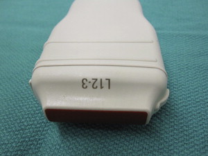
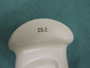
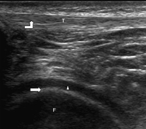
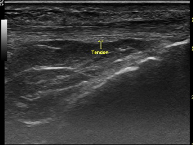
To produce an image of optimal quality, it is important to select the proper transducer for the area of interest. A transducer is described by the range of sound wave frequencies it can produce (MHz). Higher-frequency transducers produce higher-resolution images, but at the expense of beam penetration, because higher-frequency sound is more rapidly absorbed by the tissues. Lower-frequency transducers are more capable of assessing deeper structures, but they have lower resolution. Transducers also can be described as linear or curvilinear. Linear transducers produce a sound wave that is propagated in a straight line perpendicular to the transducer surface ( Fig. 1 ). Such transducers are best for evaluating linear structures like tendons. Curvilinear transducers produce an arched beam and are less commonly used, but have some advantages in evaluating deeper structures ( Fig. 2 ).
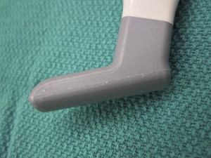
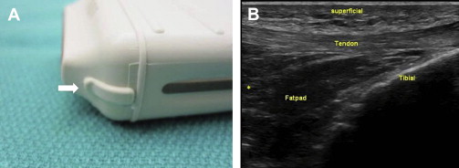
Commonly used transducers in musculoskeletal ultrasound include the high-frequency (15–7 MHz) small-footprint linear array transducer (hockey-stick transducer) ( Fig. 3 ), the high-frequency (17–5 MHz) linear transducer, and the low- to medium-frequency (5–2 MHz) curvilinear array transducer. The examiner should choose the highest-frequency transducer that can adequately image the target structure at the appropriate depth. Because most musculoskeletal structures are superficial, it is often best to use the high-frequency linear transducer, which can usually penetrate to 6 cm.
Basic Scanning Techniques
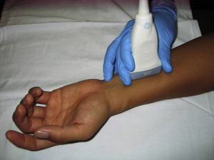
For the transducer to produce an optimal image of the underlying tissue, it is important to use enough acoustic transmission gel. After a thick layer of gel is applied to the transducer, the examiner should begin by holding the transducer between the thumb and fingers of their dominant hand, positioning the end of the transducer near the ulnar side of the hand ( Fig. 4 ). To maintain adequate pressure of the transducer on the skin and prevent involuntary movement of the transducer, it is essential to securely stabilize the transducer on the patient’s body, with either the heel of the imaging hand or the small finger.
After the transducer is properly placed on the patient’s skin, a rectangular image is produced on the monitor. The top of the image represents the tissues in contact with the transducer; the bottom of the image displays the deeper structures. The left-to-right orientation of the image can be altered using a button on the machine or by rotating the transducer 180° ( Fig. 5 ).
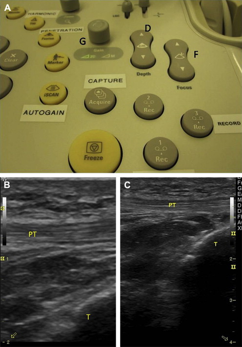
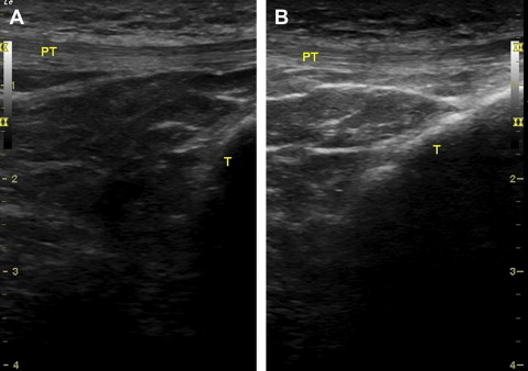
The image on the screen can be further adjusted and optimized by changing the sound-beam penetration using the depth controls. Selection of the proper transducer is also critical in evaluating the depth of a structure ( Fig. 6 ). There is an inverse relation between the frequency of the transducer and its depth of penetration, such that higher-frequency transducers are usually best to view superficial structures, whereas lower-frequency transducers are used for deeper structures.
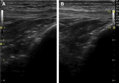
The next step in imaging is adjusting the focal zone of the ultrasound beam. The number of focal zones should be reduced to span the area of interest. The zone feature is usually displayed on the side of the image as a series of cursors or symbols. The depth and length of the focal zone position should match the position of the structure of interest ( Fig. 7 ). The examiner may adjust the gain to either increase or decrease the brightness of the echo image ( Fig. 8 ).
Advantages and Disadvantages of Musculoskeletal Ultrasound
Before integrating musculoskeletal ultrasound into practice, physicians must familiarize themselves with the distinct advantages and disadvantages of this imaging modality. When compared with other musculoskeletal imaging techniques (radiography, computer tomography, and magnetic resonance imaging), ultrasound offers numerous advantages. Perhaps the most important of these is that ultrasound offers a hands-on, dynamic examination, allowing the clinician to image in real-time, while interacting with the patient. The clinician can ask the patient for assistance during the examination and may accurately localize painful areas by palpating with the transducer and seeking patient feedback. The sonographer can also ask the patient to reproduce the abnormal or painful event while scanning dynamically.
Furthermore, ultrasound transmits no radiation to the patient or user, and thus may be used in special populations, including pregnant women and those with metal implants or other sources of imaging artifacts. Ultrasound can be of specific clinical use to physiatrists because it can be used to guide percutaneous interventions. It has the ability to image soft tissues in real-time to improve safety and accuracy of needle placement.
There are also important limitations. One of the primary disadvantages of ultrasound is that it is operator dependent and there is a steep learning curve. There is currently no certification or accreditation process required to use musculoskeletal ultrasound, so the accuracy of the examination is limited by the comfort level and skill of the examiner. Numerous examinations must be performed to establish a reliable diagnostic algorithm. For example, a study by Teefey and associates found that most errors made while using ultrasound to diagnose and measure rotator cuff tears resulted from failure of the examiner to recognize normal and abnormal structures as well as errors caused by technical limitations inherent to the test.
The clinician must be familiar with the technical limitations associated with ultrasound. Although ultrasound can provide exquisitely detailed pictures, it is not intended to image large body areas or evaluate diffuse pain. The limited field of penetration and poorer resolution at greater depths of the machine hinder its ability to evaluate deep body regions, and inability to penetrate bone prevents visualization of intra-articular structures. For example, it is limited in evaluation of anterior and posterior deep hip pathologic conditions, intercarpal joints, and ligaments in the wrist, or deep structures in the plantar midfoot. In addition, when examining the knee, deeper structures such as the menisci, cartilaginous structures, and cruciate ligaments are not well visualized. Ultrasound is also not the study of choice for imaging labral tears of the shoulder.
Normal and abnormal tissues
Describing Tissue Appearance
Musculoskeletal ultrasound can be used to identify muscles, tendons, ligaments, nerves, and vessels at a resolution of less than 1 mm. These structures can be characterized and described by their echogenicity. When there is a large difference in impedance at the interface between tissues the sound beam is strongly reflected, creating a bright echo on the image. This process is described as hyperechoic. If an image displays no echo and is black, it is referred to as anechoic, and when a weak or low echo is produced, it is termed hypoechoic ( Fig. 9 ). When the echogenicity of a structure appears equal to an adjacent structure, it can be described as isoechoic or of equal echogenicity. In general, when interpreting musculoskeletal ultrasound, a practical order of echogenicity is: bone/ligament/tendon/nerve/muscle.
In addition to their echogenicity, tissues are also described by their echotexture, which refers to their internal echo pattern. Echotexture varies based on whether a structure is imaged longitudinally or transversely. For example, tendons exhibit a fibrillar echotexture pattern when imaged longitudinally and a broom-end pattern when imaged transversely. These patterns are descriptive of the compact arrangement of hyperechoic collagen bundles within the tendons. Nerves show a fascicular longitudinal and honeycomb transverse appearance because of the hypoechoic nerve fascicles surrounded by hypoechoic connective tissue.
Muscle
To optimally identify muscle by ultrasound, the examiner must be familiar with the histologic appearance of the different types of muscle. Skeletal muscle is composed of individual fibers, and a bundle of fibers composes a fasciculus. The fascicules are visible as separate structures on ultrasound and are best identified as hypoechoic cylindrical structures separated by hyperechoic intervening connective tissue (the perimysium). Longitudinally, muscles can be described as like a feather or veins on a leaf, and when viewed transversely, they appear like a starry night ( Fig. 10 ).

During contraction of a muscle, the fibers shorten, causing an apparent increase in muscle bulk. When the muscle is contracted, the fascicles have a thicker and more hypoechoic appearance. In this contracted state partial thickness strain injuries can be revealed and the full extent of a muscle tear can be evaluated. As with all structures, it is critical to compare the muscle of interest with the contralateral side when evaluating for disease.
Additional muscle injuries that can be evaluated by ultrasound include muscle contusions and hemorrhages that appear hyperechoic initially. As soft tissues hemorrhage and begin to resorb, the hematoma becomes more echogenic, beginning at its periphery, and a residual anechoic seroma or fluid collection may be present toward the center.
Ultrasound can also evaluate a muscle hernia, which appears as a hypoechoic nodule extending through a defect in the fascia. If the examiner suspects a muscle hernia, he can directly palpate over the suspected site. This procedure allows the hernia to be felt as an individual soft-tissue nodule that appears when the muscle contracts. Application of focal pressure to the site while scanning can reveal reduction of the herniation, helping confirm the diagnosis.
Tendons
Tendons appear on ultrasound as dense, linear hyperechoic bands in a fibrillar pattern when evaluated in the longitudinal axis. When viewed transversely, they appear as hyperechoic with multiple hyperechoic foci or dots and display a broom-end echotexture. Their hyperechoic appearance is caused by the specular reflections at the interface between the fascicles and peritendineum (connective tissue containing blood vessels and nerves) ( Fig. 11 ). Because they are solid structures, tendons are normally not compressible and do not show blood flow.
However, on color or power Doppler imaging, tendons may show increased blood flow for several reasons. The increase could be seen in the setting of tendinosis, but it should not necessarily always be equated with inflammation. For example, increased blood flow is seen with Achilles tendinosis resulting from neovascularity and may correlate with pain levels.
Tendon abnormalities visible on ultrasound can range from tendinopathy to complete tears. Tendinopathy can have numerous causative factors, including overuse, external impingement, and age-related changes. Early tendinopathy appears as tendon thickening. As it progresses, the normal fibrillar pattern of the tendon is replaced with hypoechoic swelling without notable tendon fiber disruption. If the clinician suspects a severe tendinopathy, they should perform a dynamic evaluation to rule out a partial tear.
It is rare for a normal tendon to tear unless subject to an acute trauma. However, with tendinopathy the tendon is weakened and tears are frequently observed. These risk progression as a result of the weakened state. Also, a seemingly minor injury can lead to complete disruption. Chronic tendon injuries resulting in tears can lead to atrophy of the surrounding muscles, causing them to appear smaller and hyperechoic.
Ligaments
Ligaments are fibrous structures appearing similar to tendons. However, they are less compact and are composed of a more diverse pattern of collagen bundles. Ligaments are usually well defined and easily visible on ultrasound examination. However, when they occur as a focal thickening of a joint capsule, they may not be distinguishable as distinct structures. Ligaments display a hyperechoic, linear appearance on ultrasound and are optimally evaluated when they are stretched ( Fig. 12 ).
Similar to tendons, ligaments appear fibrillar during longitudinal scanning and have a broom-end appearance on transverse scans. However, ligaments can be distinguished from tendons by tracing them back to the bony structures to which they attach.
Ligamentous injuries can appear similar to tendon injuries. If the injury is low grade, ligaments appear enlarged and hypoechoic with an otherwise normal echotexture. Partial and full-thickness tears reveal fiber disruption. Partial and complete tears can be differentiated using stress testing.
Nerves
Peripheral nerves contain many nerve fibers grouped together in bundles called fascicles enclosed by an endoneurium composed of connective tissue. Fascicles are surrounded by a connective tissue sheath called the epineurium. The intrafascicular epineurium (thin septae serving to further support the nerve bundles and their vascular supply) extend inward from the epineurium.
On ultrasound, when viewed longitudinally, nerves display a fascicular pattern with uninterrupted hypoechoic bands (fascicles) surrounded by linear, interrupted hyperechoic bands (the interfascicular epineurium). In the transverse field of view, nerves may have a honeycomb appearance ( Fig. 13 ). They are usually best viewed transversely, when possible, to trace long nerve segments. Nerves and tendons can often appear similar on ultrasound, but they can be differentiated in several ways. For instance, tendons display a fibrillar pattern, whereas nerves have a fascicular pattern. Furthermore, tendons are not usually compressible, and they show more active movement on contraction of the adjacent muscles. It is also critical to evaluate tendons in the long axis, dynamically and under stress. This strategy helps identify and localize disruptions in the integrity of the tendon fibers.
Related posts:
 Ultrasonography of the Shoulder
Ultrasonography of the Hip and Lower Extremity
Ultrasonography of the Hand, Wrist, and Elbow
Musculoskeletal Ultrasound of the Ankle and Foot
Ultrasonography in Regenerative Injection (Prolotherapy) Using Dextrose, Platelet-rich Plasma, and Other Injectants
High-Frequency Ultrasound Guidance for Neurotoxin Injections
Ultrasonography of the Shoulder
Ultrasonography of the Hip and Lower Extremity
Ultrasonography of the Hand, Wrist, and Elbow
Musculoskeletal Ultrasound of the Ankle and Foot
Ultrasonography in Regenerative Injection (Prolotherapy) Using Dextrose, Platelet-rich Plasma, and Other Injectants
High-Frequency Ultrasound Guidance for Neurotoxin Injections
Stay updated, free articles. Join our Telegram channel

Full access? Get Clinical Tree


