10 Trochanteric Fractures
Sliding Hip Screw
Intertrochanteric fractures, termed trochanteric according to the Arbeitsgemeinschaft für Osteosynthesefragen/Orthopaedic Trauma Association (AO/OTA) classification, are among the most frequent hip fractures. The mean age of patients is 78 years, and women account for almost three fourths of these patients.1 The primary objective of the treatment of trochanteric fractures is to achieve rapid and stable bony union in the best possible anatomic position. This serves the main prerequisite of allowing patients to resume their preaccident levels of activities of daily life. Save for a few exceptions, trochanteric fractures are treated with internal fixation. One of the most commonly used devices is the sliding hip screw (SHS).
History
Robert Danis, in 1934, was the first to design a dynamic implant for stabilization of the femoral neck fractures (Fig. 10-1), although he never used it in practice.2 Ernst Pohl, who collaborated with Gerhard Küntscher, patented the first sliding screw in Germany in 1951.3 The patent was recognized in the United States in 1952. This implant consisted of a two-hole side-plate with a plate-barrel angle of 135 degrees. Schumpelick and Jantzen published their first experience with the use of this implant in 19534 in the German literature and then in 1955 in the English literature.5
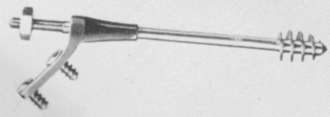
Figure 10-1 The compression hip screw of Danis of 1934.
(Originally published in Danis R. Théorie et practique de l’ ostéosynthése. Paris: Masson; 1949.)
Also in 1955, Willis L. Pugh developed a similar implant with a three-flanged nail instead of the lag screw.6 In 1957, John Charnley et al introduced a highly sophisticated 120-degree dynamic sliding screw for intracapsular femoral neck fractures.7 However, the AO/Association for Study of Internal Fixation (ASIF), founded in 1958, preferred angled blade plates for the treatment of trochanteric fractures, a preference that slowed further development of dynamic extramedullary implants in Europe until the 1970s.
In the United States, Pohl’s implant inspired the Richards Company, at the end of the 1950s, to develop a dynamic implant, later known as the Richards classic hip screw, with plate-barrel angles of 135 and 150 degrees. D. Kay Clawson, a pioneer in the use of this device, adopted it in 1959, and in 1964 he published the first results.8
At the end of 1960s, surgical treatment of trochanteric fractures underwent a crisis. It became evident that the existing implants, such as the Jewett nail or the AO 130-degree angled blade plate, were associated with high incidences of mechanical failure.9–11 As an alternative, nonanatomic reconstruction of a different type was proposed, based on the principles of resection of the comminuted zone, medial translation of the femoral shaft, and valgus reduction of the proximal fragment.9–11
In the late 1970s, Ender’s condyle-cephalic nailing became popular throughout the world.12,13 At the end of the 1980s, however, it became obvious that Ender’s nailing was also burdened by a high percentage of complications, and the method was gradually abandoned. At that time, the SHS gained ground and became a standard implant in the treatment of trochanteric fractures.14–19 The benefits of the SHS were finally recognized, and the AO/ASIF introduced their own construction of this implant, including the trochanteric support plate.20
At the beginning of the 1990s, the SHS faced competition from the first globally used intramedullary implant for trochanteric fractures—the Gamma nail, followed by other intramedullary hip nails (IMHNs). These advances triggered numerous studies comparing the strengths and weaknesses of extramedullary and intramedullary implants. Although the dispute has not been resolved fully, some investigators prefer IMHNs in unstable pertrochanteric fractures (AO/OTA 31A2) and recommend the SHS only in stable pertrochanteric fractures (AO/OTA 31A1). In intertrochanteric fractures (31A3), the use of IMHNs is recommended, although the SHS is still used quite frequently.21,22
Construction and Biomechanics
Biomechanical and clinical studies have demonstrated that the SHS sliding characteristics are influenced by plate-barrel angle, barrel length, and length of the lag screw.23–29 The greater the lag screw–plate angle and the lower the load required to initiate sliding of the lag screw, the more reliable is the impaction of bone fragments. A higher plate-barrel angle reduces the bending forces transmitted from the femoral head to the lag screw, but at the same time it increases compressive forces leading to collapse of the fragments. This collapse always takes place at the lag screw–plate angle, rather than at the neck-shaft angle of the reduced fragments. The contact forces between the barrel and the lag screw increase while the amount of engagement of the lag screw in the barrel simultaneously decreases. The greater the length of the screw extending from the barrel, or the shorter the length of the barrel, the more resistance there is to sliding and the greater the potential is for jamming. This means that during the surgical procedure, it is necessary to control the amount of the lag screw engaged in the barrel. Short contact implies an increased risk of jamming (Fig. 10-2). Maximal sliding capacity of an SHS is limited by the length of the lag screw shaft between the barrel and the lag screw thread (Fig. 10-3). Clinical experience has shown that jamming of the sliding mechanism occurs very rarely in the SHS, almost always when engagement of the lag screw in the barrel is inadequate.30
Standard procedure is to use four cortical screws to attach the side-plate to the femoral shaft. According to the biomechanical study conducted by Yian et al,31 three screws are sufficient. McLoughlin et al recommended the use of only two screws32 (Fig. 10-4), a recommendation supported by clinical studies.33–37 The benefit of a two-hole side-plate is a less invasive approach, shorter duration of surgery, and less risk of injury to femoral vessels.37
Indications
Classification of Trochanteric Fractures
The terminology of fractures of the trochanteric segment is highly confusing, and original classifications are often misinterpreted.38,39 Evans,40 Boyd and Griffin,41 Boyd and Anderson,42 Jensen,43 AO/ASIF,44 and OTA45 classifications refer to these injuries as trochanteric fractures. Kyle et al46 and many of their followers use the term intertrochanteric fractures. The benefit of the Evans, AO/ASIF, and OTA classifications, as compared with other classification systems, is that they distinguish between two basic groups of trochanteric fractures (i.e., pertrochanteric [31A1 and 31A2] and intertrochanteric [31A3] fractures) that have very different characteristics and treatment needs.47
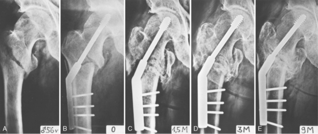
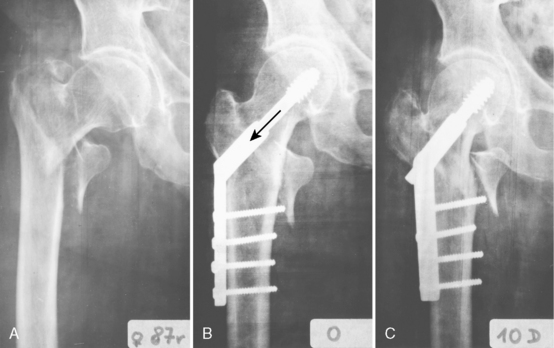
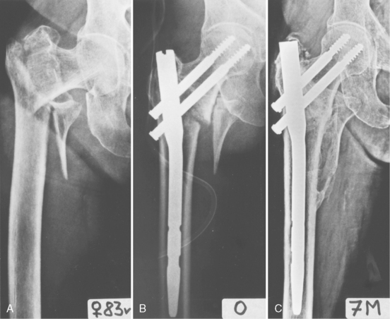
Pertrochanteric fractures (31A1 and 31A2) are characterized by the primary fracture line’s passage from the greater trochanter obliquely and inferomedially to the lesser trochanter. In addition, in unstable fractures, a flat posterior fragment is avulsed and bears the posterior aspect of the greater trochanter, the intertrochanteric crest, and the lesser trochanter. As a result, the only part left of the greater trochanter on the diaphyseal fragment is a mere spike of the cortical bone bearing the vastus lateralis ridge. The proximal fragment in unstable pertrochanteric fractures is formed only by the femoral head and neck. No muscle is attached to this fragment, and reduction of the fracture is, with few exceptions, quite easy. Firm implant fixation in the proximal fragment is feasible only in the subchondral bone of the femoral head. In dynamic implants, compression of the two main fragments (i.e., the head-neck fragment and the diaphyseal fragment) takes place in the lag screw axis (Fig. 10-5).
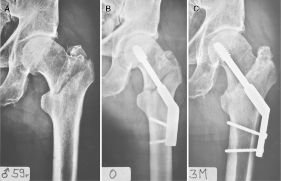
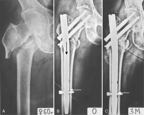
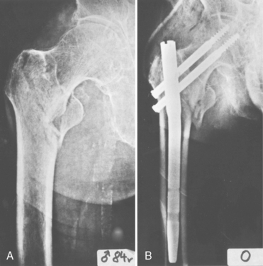
Intertrochanteric fractures (31A3) are also called reverse intertrochanteric, reverse oblique intertrochanteric, high subtrochanteric, and subtrochanteric fractures. The fracture line passes from the base of the greater trochanter obliquely and proximomedially, or it is shaped like an inverted V. The proximal fragment is formed by the femoral head and neck and the greater trochanter, including the vastus lateralis ridge. Attached to this fragment are the gluteus medius and gluteus minimus muscles, the vastus lateralis muscle, and sometimes also the iliopsoas muscle. For this reason, reduction of the fracture can be troublesome. Bone stock for fixation of an IMHN in the proximal fragment is formed by the subchondral bone of the femoral head, the tip of the greater trochanter, and often also by the lateral cortex of the proximal fragment. Compression of the main fragments along the femoral shaft axis (i.e., in the axis of the IMHN) is important for healing of intertrochanteric fractures (31A3) (Fig. 10-6). The SHS does not provide this compression.
Revised Concept of Instability of Pertrochanteric Fractures
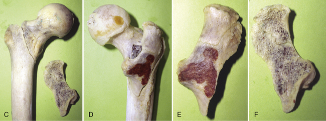
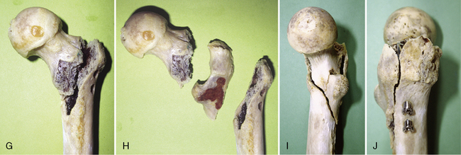
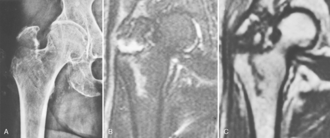
One traditionally reported cause of instability in pertrochanteric fractures is a defect of the medial cortex.39,55 The experience of Bartoníček et al, based on 19 postmortem specimens of pertrochanteric fractures, is different (Fig. 10-7).56 These investigators found no defect of the medial cortex in any of the unstable fractures. Instability was, in all cases, caused by avulsion of the posterior triangular flat cortical fragment formed by the posterior aspect of the greater trochanter, intertrochanteric crest, and part of the lesser trochanter. Magnetic resonance imaging (MRI) analysis of occult pertrochanteric fractures revealed that avulsion of the posterior fragment starts before the primary fracture line, passing mediodistally from the greater trochanter, and reaches the lesser trochanter56 (Fig. 10-8). The posterior fragment is often split into a superolateral portion carrying the greater trochanter and an inferomedial portion bearing the lesser trochanter. The only part of the greater trochanter that remains attached is a spike of thin lateral cortex. On the medial surface of the trochanteric segment, the fracture lines converge into a Y-shaped junction, which makes anatomic reduction of the medial cortical shear unstable.
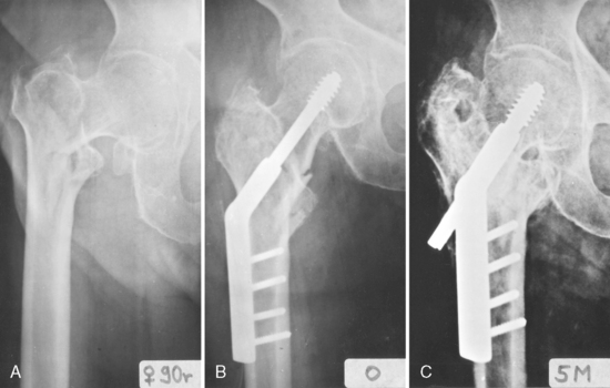
When an unstable trochanteric fracture is stabilized with a dynamic implant, the femoral shaft tends to displace medially. This situation occurs primarily in unstable pertrochanteric fractures (31A2). The base of the femoral neck has no medial support that would prevent collapse of the fragments. The inferomedial cortex of the femoral neck slides into the medullary canal, and at the same time the proximolateral part of the femoral neck base rests against the greater trochanter. The spike of thin cortical bone that remains of the greater trochanter in most unstable pertrochanteric fractures is easily fractured and is not able to halt the progressive collapse of fragments (see Fig. 10-5C).
The importance of the lateral wall in preventing the loss of medial cortical contact has been described by several investigators.57–60 The results of collapse are a medial shift of the femoral shaft and loss of the medial cortical support. These changes increase the risk of varus angulation and mechanical failure of fixation.
Comparison of Sliding Hip Screw and Intramedullary Hip Nail
Biomechanics
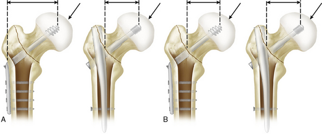
The main strength of the IMHN, as compared with the SHS, is its shorter leverage, leading to reduced stress on the implant. This property applies only to fixation of implants in the distal fragment, however. With regard to fixation in the proximal fragment, there is no difference between an SHS and an IMHN in pertrochanteric fractures (31A1 and 31A2). The load acting on the femoral head is the same with both the SHS and the IMHN (Fig. 10-9). This load is transmitted to the tip of the lag screw. The interface between the lag screw and the bone of femoral head is a critical point of the whole construct. Fixation between the implant and the diaphyseal fragment is, save for a few exceptions, usually more stable. The bending force acting on the femoral head and neck depends on the neck-shaft angle. The greater this angle, the lower is the bending force.61 The maximal angle in most IMHNs is 135 degrees. Side-plates in the SHS offer a choice of wider angles of 140, 145, and 150 degrees. Therefore, greater valgus reduction, respecting the relationship between the reduction angle and the implant angle, is possible only with SHS.
The SHS is fixed in the proximal fragment by only one lag screw. With some IMHNs, it is possible to use a combination of a lag screw and an antirotation pin, or two lag screws. Some biomechanical studies,62 as well as clinical experience, have shown that fixation by two lag screws is more secure than fixation using a single lag screw. In the SHS, the length of the barrel of the sliding mechanism is greater than that of the IMHN, in which the length of the barrel is determined by the diameter of the proximal part (body) of the nail.
At the level of the fracture site, the IMHN prevents significant medial displacement of the femoral shaft. The nail body provides support to the base of the femoral neck and thereby limits collapse of the fragments (Fig. 10-10). The SHS has no such mechanism; because of its position, the trochanteric support plate exerts much less control of the collapse63 (see Chapter 12).
Related posts:
 Investigation and Management of Postoperative Delirium
 Rehabilitation: Improving Outcomes for Patients Following Fractures of the Proximal Femur
 Subtrochanteric Fractures: Plate Fixation
 Femoral Neck Fractures: Treatment of Nonunion
 Subtrochanteric Fractures: Intramedullary Fixation
 Complications of Trochanteric Fractures
Stay updated, free articles. Join our Telegram channel

Full access? Get Clinical Tree


