Transpedicular Fixation: Open
Mark S. Eskander
Jesse L. Even
James D. Kang
Roy-Camille et al. (7) introduced the idea of transpedicular screw fixation to the forefront of spinal surgery in 1963. Since then, open transpedicular fixation techniques are one of the most utilized in the treatment of a variety of spinal disorders. Pedicle screw fixation can rigidly control the three columns of the spine but needs an intact pedicle to do so. Some of the indications for transpedicular fixation include resisting translational instability, resisting axial instability, and controlling complex deforming forces (5,6).
INDICATIONS
There are many instances where transpedicular fixation is utilized by the surgeon to treat a particular problem. A clear understanding of the clinical problem and a patient’s particular anatomy will determine when to use transpedicular fixation techniques (4). The following are some disease processes that are amenable to transpedicular fixation.
Degenerative disease
Spondylolisthesis
Disk degeneration (after multiple herniations)
Degenerative scoliosis
Trauma
Deformity
Scoliosis
Kyphosis
Tumor
Metastatic
Primary
Malunion (flatback syndrome, angular deformities after prior surgery)
Osteomyelitis (if infection is under control and spine is unstable)
Cervical 7 pedicle screw (when the C7 lateral mass is disrupted after foraminotomy)
While transpedicular fixation of the spine has many uses and indications, there are several circumstances where it is contraindicated and may be a detriment to the patient and the spinal reconstruction construct.
CONTRAINDICATIONS
Osteopenia/osteoporosis
Atrophic/dystrophic pedicles
Congenital absence of pedicles
Fractures that disrupt the pedicle
Active infection
 FIGURE 24-1 Lateral scout view from her CT scan. This scan illustrates her kyphotic deformity from her burst fractures at L3 and L4. |
PREOPERATIVE PREPARATION
As with all areas of spinal surgery, preoperative planning is essential. After a thorough history and physical examination, complete radiographic evaluation of the spine is next. This is a case of a 20-year-old female who fell off a roof and sustained L3 and L4 burst fractures. The plan for this patient was a posterior spinal fusion (PSF) L2 to Ilium with iliac crest bone graft (ICBG), repair of traumatic durotomy, and reduction of retropulsed fragments from the canal. The patient’s preoperative studies are shown; Figure 24-1 is a lateral scout view from her computerized tomography (CT) scan. This scan illustrates her kyphotic deformity from her burst fractures at L3 and L4. Figure 24-2 is a midsagittal CT showing the severity of the burst fractures with special attention to the canal compromise at L4 and the loss of lordosis. There are also some minor compression fractures at T11-L1. Figure 24-3 is a midsagittal T2-weighted magnetic resonance imaging (MRI) showing burst fractures with significant canal compromise at L4.
 FIGURE 24-2 Midsagittal CT showing the severity of the burst fractures with special attention to the canal compromise at L4 and the loss of lordosis. There are also some minor compression fractures at T11-L1. |
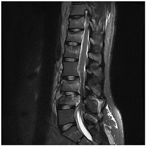 FIGURE 24-3 Midsagittal T2-weighted MRI showing burst fractures with significant canal compromise at L4. |
Typically, our patients will have anteroposterior (AP) and lateral (flexion and extension) plain radiographs. Often more advanced imaging will ensue. This can include MRI and CT with and without myelography. If the cervical spine is being evaluated, a CT angiogram is preferred to help understand the vasculature in the neck. It is also important to note the alignment of the patient’s spine when positioned on the operating room table with a cross-table lateral radiograph. This image is very useful to gauge the trajectory of the screw placement intraoperatively. This is particularly helpful in the setting of instability, secondary to trauma; infection; or tumor, where restoring spinal alignment is of the upmost importance. It is also helpful after performing osteotomies to visualize the correction that was obtained.
TECHNIQUE
Patient Positioning
The patient is gently flipped onto the Jackson table in the prone position. The pads of the Jackson frame support the chest and the iliac wings, allowing for gravity-assisted reduction of the fractured spine. The knees are slightly flexed with pads under each knee. The face is held in a prone view headrest with foam cushions. The eyes are free from any contact and pressure points. The arms are positioned on arm holders with padding. The palms are placed in the pronated position, and the elbows are flexed at 90 degrees. The shoulders are abducted and externally rotated to 90 degrees but forward flexed to 20 degrees to keep tension off of the brachial plexus.
Approach
After being prepped and draped, a midline incision with a no. 10 blade is then made from the bottom of L1 down to the sacral junction. This incision is then taken down to the fascia level using a Bovie electrocautery device. The fascia is then divided to expose the posterior aspect of the spinous process and lamina of L2, L3, L4, L5, and S1 as well as the sacral alar area. A Richardson retractor is then utilized to pull tension on the muscular attachments on the facet capsules, while the Bovie is used to carefully dissect the tissues of off the capsule and to further the exposure out to the transverse process. The transverse processes of L2 through L5 are exposed along with the sacral ala of S1. The posterior aspect of the posterior superior iliac spine (PSIS) is then also exposed through the same midline incision. After the exposure is completed, a Kocher is placed at the L3 spinous process and a lateral x-ray was then taken to confirm levels. Figure 24-4


Related posts:

Stay updated, free articles. Join our Telegram channel
Full access? Get Clinical Tree
