Transpedicular Fixation: Minimally Invasive
Siddharth B. Joglekar
James D. Schwender
Pedicle screw instrumentation has a history that spans less than 50 years since the first description of pedicle screw plating by Raymond Roy-Camille in 1970 (28). Owing to their biomechanical and clinical superiority, pedicle screws have become the spinal anchors of choice for fusion over the last two decades. More recently, less invasive paramedian and percutaneous pedicle screw placement has become widely used to reduce the surgical trauma of the erector spinae musculature. Percutaneous pedicle screw insertion may be traced back to Magerl (17) who first described the “fixateur externe” for the lumbar spine in 1980 and 1984. This technique included percutaneous insertion of posted Schanz screws into the pedicles followed by external bridging of the construct with rods. While the first description of percutaneous pedicle screw instrumentation followed just 10 years after introduction of pedicle screws, it has taken the next three decades for surgeons to develop it into a safe and universally acceptable technique.
Mini-open placement of screws through the transsacrospinalis posterolateral portal with the help of specialized retractor systems has also become a popular minimally invasive spine (MIS) technique. The development of MIS screw placement techniques has been paralleled by the development of radiologic and computer-aided guidance systems to improve accuracy of screw placement.
INDICATIONS
Minimally invasive pedicle screw placement can be used to stabilize the spine in almost every situation where open placement of screws is indicated including degenerative, traumatic, infectious, and neoplastic etiologies. In obese patients in whom open placement would be challenging, MIS screw placement may be preferable.
CONTRAINDICATIONS
There are no absolute contraindications to minimally invasive placement of pedicle screws. MIS pedicle screws would be relatively contraindicated in the following situations:
Lack of technical expertise or adequate experience
Lack of imaging or navigation equipment when percutaneous placement is being considered
Severe deformities of the spine, sclerotic pedicles, very narrow pedicles, and very long multisegment fixations when MIS techniques have been assessed to be technically unsafe or challenging on the preoperative planning
When MIS techniques may be noncompatible with the pathology being treated, for example, neoplastic disorders or infections
PREOPERATIVE PREPARATION
Careful preoperative planning is essential with a complete history and physical examination along with the aid of radiographs and three-dimensional (3D) imaging. The following factors need to be considered carefully in the preoperative plan:
Medical clearance for surgery
The indication for surgery to treat the appropriate pathology
Type of fusion considered: posterolateral and/or interbody
Type of screws (tulip heads versus posted)
Type of approach (mini-open versus percutaneous)
Type of bone graft (allograft versus iliac crest graft versus biologics)
Type of retractor systems (expandable versus tubular)
Instrumentation system to be utilized and availability of all specialized equipment and instruments
Type of rods and rod introduction system
Type of navigation/imaging guidance
Need for neuromonitoring
Pedicle morphology: size and angulation of the pedicles
Anatomy of the pedicle in terms of angulation, size, and pedicle length is variable throughout the spine (20,36,39). Pedicles in the thoracic region are significantly smaller and more variable in size and shape than those found in the lumbar region. The transverse diameter is generally much smaller than the vertical diameter for each pedicle, which demands much greater screw placement accuracy in the transverse plane at each level. Transverse pedicle diameters in the thoracic spine are reported to range from 4.5 to 7.8 mm with an increasing trend from T1 to T12, whereas the pedicle angulations in the transverse plane vary from 0 to 30 degrees with a decreasing trend from T1 to T12 (6,36,39). In the lumbar spine, the transverse pedicle diameter gradually increases from L1 to L5 (7.4 to 18.3 mm), and the transverse plane lumbar pedicle angle increases from L1 to L5 (25 to 40 degrees) (5).
TECHNIQUE
There are two main techniques in use for MIS screw placement:
Mini-open placement
Percutaneous screw placement
There are further variations in each technique based on the imaging/navigation technique utilized. The following variations may be possible:
Mini-open placement through a tubular retractor system:
Free-hand screw insertion with direct anatomic visualization
Image-guided screw placement (C-arm) without navigation for assistance
Image-guided screw placement (C-arm or CT scan) with computer-aided navigation for assistance
Percutaneous screw placement relies on image-guided techniques, and free-hand insertion is not possible. Navigated and nonnavigated insertion is possible.
Mini-Open Pedicle Screw Placement
Mini-open MIS fusions utilize the surgical corridor as described by Wiltse et al. (37) between the multifidus and longissimus paraspinal muscles (Fig. 25-1). This trajectory is ideal for both pedicle screw placement and decompression and fusion techniques.
Fluoroscopy is used to make the appropriate skin incisions. The skin incisions are made 2.5 cm in vertical length and 4 to 5 cm off midline. Sequential dilators are then passed through the fascia and docked onto the facet joint. A tubular retractor (typically 22 or 26 mm) is then docked and secured over the dilators. The use of an expandable retractor allows the blades to expand cephalad or caudad creating a corridor for pedicle screw placement (Fig. 25-2). Soft tissue is cleared to expose the standard pedicle screw entry points. Screws can be placed using a variety of methods including free hand, under C-arm guidance, or utilizing navigation depending upon surgeon preference. In addition, both posted and tulip-style pedicle screws can be used if working through the tubular retractor systems that are available.
Surgeon preference dictates the sequence of steps during a minimally invasive fusion. Early on in a surgeon’s experience, it may be easiest to place the pedicle screw tracts first prior to the decompression or facetectomy. This will preserve “normal” anatomy to help orient the surgeon to
the anatomic starting points. However, it is the author’s experience that it is more efficient to perform the transforaminal lumbar interbody fusion (TLIF) followed by appropriate decompression prior to screw tract preparation and screw placement. This minimizes the surgical exposure during the portion of the procedure that requires the most expansion of the modular retractor and thereby helps to limit muscle creep (Fig. 25-3).
the anatomic starting points. However, it is the author’s experience that it is more efficient to perform the transforaminal lumbar interbody fusion (TLIF) followed by appropriate decompression prior to screw tract preparation and screw placement. This minimizes the surgical exposure during the portion of the procedure that requires the most expansion of the modular retractor and thereby helps to limit muscle creep (Fig. 25-3).
 FIGURE 25-1 Schematic diagram of the lumbar spine in the axial plane. |
The major advantage of this technique versus the percutaneous screw technique is the ability to directly visualize the bony anatomy, thus reducing the requirement of fluoroscopy. In addition, facet joint and posterolateral fusion can be accomplished through the same tubular retractor that the pedicle screws are placed.
Percutaneous Pedicle Screw Placement
Pedicle screws can be safely and effectively placed percutaneously, thus avoiding the additional dissection required for the placement of traditional and mini-open pedicle screws. Percutaneous pedicle screw placement has the advantage of less muscle damage and less potential damage to the medial branch nerve (innervation of the multifidus) and can be used effectively over long-segment fusions. The placement of percutaneous pedicle screws can require more operative time and more x-ray exposure for accurate placement. When using the fluoroscopic technique, the orientation of the C-arm beam is of critical importance. The anteroposterior (AP) images must be true AP images of each pedicle for screw placement (Fig. 25-4). The spinous process should be in the midline of the vertebral body, equally spaced between both pedicles. The superior and inferior endplates should be parallel, and the pedicles should be appropriately located at the caudal end of the ascending articular process. On the lateral view, the superior endplate should appear as one line, and the pedicles should overlap and thus appear as one (Fig. 25-5). True AP and lateral radiographs are of critical importance because small variance can produce erroneous placement of the pedicle screw.
The pedicle of interest is localized utilizing the AP fluoroscopic image. The skin is incised just lateral to the pedicle. The thoracolumbar dorsal fascia and muscle fascia are incised. A Jamshidi trocar is used to cannulate the pedicle. The ideal starting point is at the 10 o’clock and 2 o’clock positions on the left and right pedicles, respectively. The Jamshidi is slowly advanced a few millimeters into the pedicle. A lateral fluoroscopic image is obtained and should confirm that the Jamshidi is placed within the center of the pedicle. Under AP fluoroscopic imaging, the Jamshidi is advanced about 20 mm. The tip should stay lateral to the medial border of the pedicle. A lateral image is obtained and should show the tip of the Jamshidi at or past the neurocentral junction (Fig. 25-6). If so, the Jamshidi can be safely advanced to its desired depth. If the tip of the Jamshidi is at or medial to the medial border of the pedicle on the AP view and not yet passed the neurocentral junction on the lateral view, then it has likely breached the medial border of the pedicle.
 FIGURE 25-2 Exposed anatomy of the lumbar spine through a modular tubular retractor system. |
 FIGURE 25-3 Completed decompression and TLIF with pedicle screws placed under direct visualization. |
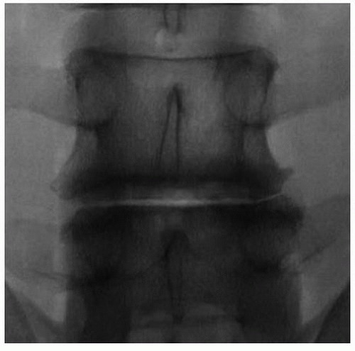 FIGURE 25-4 True AP of the lumbar spine. |
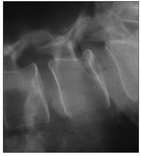 FIGURE 25-5 True lateral of the lumbar spine. Note the endplates are parallel and overlap. |
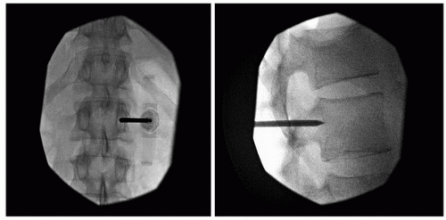 FIGURE 25-6 AP and lateral images with a Jamshidi trocar inserted. Note that the trocar tip remains within the confines of the pedicle on the AP when at the neurocentral junction on the lateral. |
After the Jamshidi is placed appropriately, a guidewire is passed. This is repeated at each pedicle. The pedicle screw is then placed over each guidewire, and then the appropriately sized rod is passed. It is critical to continue periodic lateral fluoroscopic visualization to avoid advancing the guidewire anteriorly. Avoid kinking of the guidewire, and remove any dried blood to minimize the risk of guidewire advancement while inserting the screw. In addition, remove the guidewire when the pedicle screw reaches the neurocentral junction.
When first performing these procedures, the authors encourage the liberal use of fluoroscopy or computer-aided navigation. With experience, radiographic exposure and operative time will diminish (Fig. 25-7).
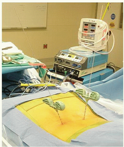 FIGURE 25-7 K-wires placed through the Jamshidi trocar prior to pedicle screw insertion. |
PEARLS AND PITFALLS
When placing pedicle screws through the MIS tubular retractor technique, remember to move the retractor for accurate visualization of the required bony anatomy. Do not let the retractor dictate what you see and do.
When first placing screws through a tubular retractor, expose the pars and the medial portion of the transverse process clearly.
Pedicle screw tracks may be easier to prepare prior to performing the decompression and facetectomy when more bony landmarks are present.
When placing percutaneous screws, fluoroscopic images must be “perfect” AP and lateral views. Otherwise, percutaneous screw placement may be aberrant.
Start simple in terms of complexity of case selection.
POSTOPERATIVE MANAGEMENT
The postoperative rehabilitation plan for these patients is similar to an open pedicle screw placement technique with the exception that mobilization and discharge of the patients may be accelerated as a result of the reduced pain and need for narcotics due to the minimally invasive approach. Wound care strategies may be followed as per the surgeon preference. Bracing needs should be individualized based on the pathology treated and the strength of the fixation construct. We usually do not recommend the use of brace immobilization for instrumented spinal fusions.
Related posts:

Stay updated, free articles. Join our Telegram channel

Full access? Get Clinical Tree


