There has been an increase in the use of ultrasound (US) to help guide interventional procedures involving the musculoskeletal system. To perform these procedures safely and accurately, two steps must occur. First, the appropriate structure must be localized using diagnostic US imaging. Second, a needle must be guided under constant visualization toward the targeted tissue. Although US imaging can help place the needle and, hence, therapeutic medication more accurately, there is still debate about whether or not image-guided procedures result in improved outcomes. This article discusses the advantages and disadvantages of performing US-guided injections and describes injection principles and techniques. Studies examining the efficacy of US-guided procedures are reviewed.
Advantages/disadvantages of ultrasound image guidance
With its associated technological improvements and associated lack of ionizing radiation, ultrasound (US) imaging is ideal for guiding most musculoskeletal interventional procedures. Unlike other imaging modalities, US has a unique advantage in that it can visualize soft tissues, bony landmarks, and the needle using real-time scanning, allowing dynamic visualization. In addition, there are no known contraindications to US. Although it allows identification of normal vasculature, concomitant use of Doppler imaging also identifies increased vascularity associated with certain pathologic conditions. US-guided destruction of this neovascularization associated with tendinopathy is known to improve clinical outcomes.
There are also disadvantages associated with using US for injection guidance. Requiring some degree of manual dexterity, US-guided injections are associated with a steep learning curve, initially requiring added time and preparation to perform. This added time may make patients anxious because previously placed blind injections may have been done more quickly with less setup required. Because using US guidance is associated with added cost, it must be determined whether or not image guidance is needed, especially when there is existing controversy about whether or not accurate placed injections provide added therapeutic benefit.
Technical Considerations
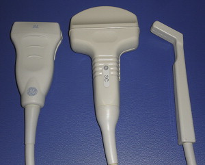
Before performing any interventional musculoskeletal procedure with US guidance, tissues must be accurately identified and optimally imaged. This requires not only a sound knowledge of anatomy but also appropriate selection of US equipment and settings. A complete review of US machine knobology is beyond the scope of this article. Selection of an appropriate probe can be crucial in obtaining optimal visualization. In general, lower-frequency curvilinear probes (ie, 3–5 MHz) are best for imaging and targeting deeper structures, such as the hip joint ( Fig. 1 ). Lower-frequency transducers allow greater US penetration but this improved penetration comes at the cost of poorer resolution. Conversely, higher-frequency probes, such as 5- to 15-MHz linear array transducers, lacking the depth penetration of lower-frequency transducers, are associated with superb resolution and are ideal for injecting superficial tissues (see Fig. 1 ). High-frequency, hockey stick probes have a smaller footprint and enable better contact between small irregular surfaces (see Fig. 1 ). This smaller footprint, hence, improved US probe contact, improves visualization and may make US-guided injections around the foot and hand easier to perform.
Probe and Needle Orientation
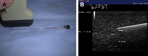
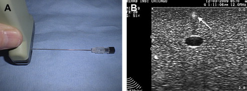
Structures can be imaged with US using a longitudinal or long-axis view or a transverse, short-axis view. Imaging each body part requires visualization with US using both orthogonal views. When performing interventional procedures the needle can be placed longitudinally or parallel to the US probe or it can be placed in short axis or perpendicular with respect to the transducer. When the needle is placed in parallel, it is considered in plane with the US probe ( Fig. 2 A). In some ways, the in-plane approach can be considered the preferred technique because the entire length of the needle, including the tip and shaft of the needle, can be identified at all times (see Fig. 2 B). Constantly visualizing the tip of the needle is vital because this ensures that no unwanted structures are injured or injected. When a needle is placed perpendicular or in the short axis to the US probe, it is considered out of plane ( Fig. 3 ). When performing US-guided injections, various combinations of probe orientation to the target tissue and needle exist ( Table 1 ). Determining which approach to choose is often a matter of personal preference but certain advantages and disadvantages exist.
| Tissue View | |||
|---|---|---|---|
| Needle View | Longitudinal | Short axis | |
| In plane | Longitudinal/in plane | Short axis/in plane | |
| Out of plane | Longitudinal/out of plane | Short axis/out of plane | |
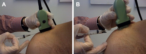
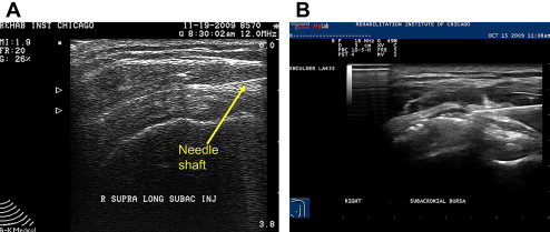
The in-plane technique has disadvantages. The most obvious is realized when injecting very superficial tissues with the in-plane technique. Often there is not enough subcutaneous tissue to accommodate placement of the needle underneath the US probe and into the targeted tissue ( Fig. 4 A). To avoid this limitation, a stand-off approach may be used. With this technique, sterile gel is heaped up underneath the probe and a gel interface is created between the skin and probe. The needle is then placed in plane with the US probe and advanced into the superficial targeted tissue with constant direct visualization (see Fig. 4 B).
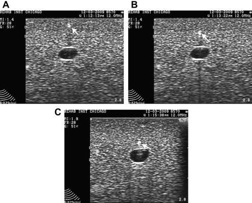
The out-of-plane needle technique also has inherent advantages and disadvantages. The limitation of this technique is that no matter where the needle is visualized along its shaft, the needle appears as a small echogenic circle or dot (see Fig. 3 B). Potential injury exists when only the shaft is seen because it is unknown where the actual bevel is located. The out-of-plane technique is ideal for injecting superficial small articulations, although injecting deeper structures can also be done via a walk down technique. With this technique, the needle is first visualized superficially, then withdrawn slightly, and with each ensuing pass repositioned deeper, eventually reaching the targeted tissue ( Fig. 5 ).
The indirect technique can be used for superficial structures, such as the acromioclavicular (AC) joint. With this technique, both sides of the joint are first identified with US and a mark is placed on the skin demarcating the borders of the joint. Next the needle is placed between the markers and the transducer is replaced so that proper needle placement is confirmed.
A safe injection technique has also been described. With this technique, US is used to define the margins of an intended target that lies underneath the transducer. A scan is first done transversely and marks are made on either side of the target. Then the probe is rotated 90° and marks again are made defining the borders of the target. The transducer is removed and the marks are connected, eventually making a crosshair. A needle is placed blindly into the center of the cross hair into the structure. Because the needle is not actually visualized during the procedure, this technique should not be considered US guided.
Factors Affecting Needle Identification
US-guided interventional procedures require that not only the targeted tissue is identified but also the needle and needle tip are constantly visualized. If the needle tip is not constantly visualized during the procedure, there is a risk of placing the needle and, hence, medication into unwanted tissue. If the needle tip goes out of view during the procedure, the needle should no longer be advanced. Instead, it is recommended that the probe be moved or reoriented until the needle is again identified. The urge to move the needle to find the probe should be resisted because this leads to potential injury to underlying tissue. It is only when the needle is relocated that it should be advanced toward the identified target.
Maximizing needle echogenicity is the best way to consistently identify a needle during a US-guided procedure. Several factors affect a needle’s echogenicity. Although using a larger gauge may help when aspirating cysts, calcifications, or fluid collections, such as hematomas, needle brightness or echogenicity is more dependent on the orientation of the US beam than actual needle gauge. Maintaining the probe parallel to a needle and, hence, the US beam perpendicular to the needle optimizes echogenicity. Although larger needles may help needle localization, when the probe is oriented parallel to the needle, a 22-G needle also is easily recognized (see Fig. 2 B). Echogenic needles, therefore, with their added cost, typically are not necessary when proper beam orientation is used. Some articles, however, have suggested that certain types of needles may be beneficial for performing regional anesthesia. When a US beam angle strikes a needle regardless of gauge at an angle other than 90°, some of the beam is reflected away and standard needles become hypoechoic and less conspicuous ( Fig. 6 ).
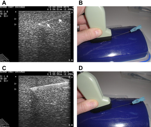
Injecting tissues at greater depth with US guidance carries certain technical challenges. Identification of the needle tip can become more difficult when using a more oblique needle trajectory to reach deeper targets ( Fig. 7 A, B). This is due to the fact that the US beam strikes the needle at an angle other than 90°. Although beam steering may improve visualization, not all machines have this capability. The simple way to improve needle echogenicity during an oblique injection is to reorient the transducer so that the probe remains parallel to the needle. During an injection, this may simply be accomplished by tilting the probe using a heel-toe maneuver (see Fig. 7 C, D). When a linear array transducer is tilted, contact with the skin surface may be lost. Filling this void between the probe and the skin helps maintain conductance of the beam into the tissue. A simpler strategy, especially for deeper injections, is to use a curvilinear probe that has sector scanning. With either of these strategies, the beam strikes the needle closer to a 90° angle, maximizing needle echogenicity.
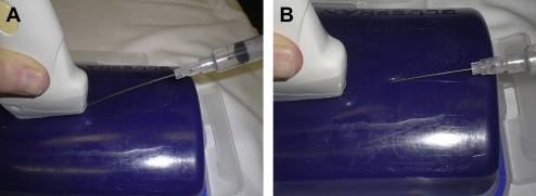
Another technique that may improve needle echogenicity when injecting deeper tissues is to use a needle entry point that is located further away on the skin surface. In this way, a less oblique trajectory can be used to reach the targeted tissue ( Fig. 8 ). When an entry point is located further away on the skin, however, a longer needle may be needed and it may be difficult to simultaneously obtain visualization of the needle and target under the transducer. Manipulating longer, potentially less echogenic needles, located further away from the target tissue and transducer, makes injecting deeper tissues with US guidance technically more challenging (especially for a novice ultrasonographer).
Planning the Injection
Before performing any US interventional procedure, it is recommended a preliminary scan be performed. This preliminary scan serves several purposes. The first is to locate the target tissue while confirming the diagnosis. It also helps identify any pertinent structures, such as vessels and nerves, that are to be avoided during the injection. Performing a preliminary scan can also help determine whether or not it is better to use an in-plane or out-of-plane approach. It also helps establish the most appropriate needle trajectory.
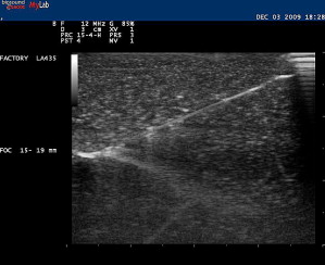
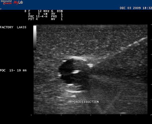
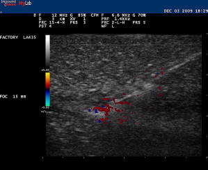
A trial run can be made with a smaller-gauge needle while placing an anesthetic. With this trial run, it can be determined whether or not an entry point and angle toward the target are appropriate before performing the actual therapeutic procedure. Injecting local anesthetic or any other fluid during this procedure enhances the visibility of the needle because the hyperechoic shaft is more apparent within the hypoechoic fluid ( Fig. 9 ). This technique, sometimes referred to as hydrodissection, can also help with needle localization if the needle becomes less conspicuous. Other investigators have felt that microbubbles within the anesthetic also aids in needle identification. Using Doppler US while jiggling a needle can also help relocate the needle should visibility be compromised during the procedure ( Fig. 10 ). Doppler US can also be used to track the flow of the injectant during the procedure.
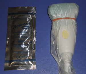
Although there is no accepted way of performing each US-guided musculoskeletal procedure, preparing for injections should be emphasized. First, every effort should be made to reduce the chance of infection. Some clinicians prefer bathing the US probe in a sterilizing solution, whereas others use a sterile condom over the probe with drapes placed over a sterilely prepared area ( Fig. 11 ). The freehand technique is somewhat challenging but is a commonly used method when injecting tissues with US guidance. With the freehand technique, one hand is controlling the probe while the other hand places the needle into the appropriate position. The freehand technique is somewhat of a misnomer because it does not allow clinicians a free hand to control settings on the US machine, reach for medications, remove a needle stylet, aspirate before injection, change out syringes, or store appropriate images. The transducer can be put down so that these adjustments can be made or, ideally, with a two-person technique, an assistant can be present who can help with various needs related to the procedure.
Although many of these procedures can be performed with patients sitting or lying, it is ideal that patients be placed in a comfortable position. If needed, however, they can be laid supine or in Trendelenburg should a vasovagal episode occur. Proper ergonomics should be adhered to as well. Holding a probe or needle for a prolonged period of time can create hand fatigue. Having a US screen positioned improperly also causes additional problems for the neck or back while attempting to visualize an improperly placed screen. Finally, it is recommended that appropriate images be archived. These stored images should include patient identification, facility, date of service, side injected, and anatomic site.
Injection techniques
Upper Limb -Shoulder Complex
Subacromial bursa
The subacromial bursa can be injected with US guidance using a high-frequency linear array probe placed in a longitudinal position over the anterolateral shoulder. Patients can be in a side-lying or seated position with the arm in an extended and internally rotated position. If this position cannot be tolerated, a modified version of this position can be performed. The needle, typically 25G, 1.5 inches, is placed in plane with the probe and placed directly into the subacromial bursa under direct visualization ( Fig. 12 A). Hydrodissection using lidocaine often delaminates the subacromial bursa, confirming accurate placement of medication (see Fig. 12 B). This is followed with a corticosteroid of choice.
Although some studies have shown approximately a 70% miss rate when performing blind subacromial injections, others have shown that blind injections are as accurate US-guided ones. Performing US-guided subacromial steroid injections can also result in significant improvement in shoulder abduction range of motion and pain compared with a blind injection technique in patients with shoulder pain. Some studies, however, have shown that there is no significant difference comparing an intramuscualr dose of corticosteroid with a US-guided subacromial injection in patients with rotator cuff disease. One study has shown that US-guided sodium hyulronate injections can improve pain from rotator cuff tendinopathy compared with US-guided saline injections.
Acromioclavicular joint
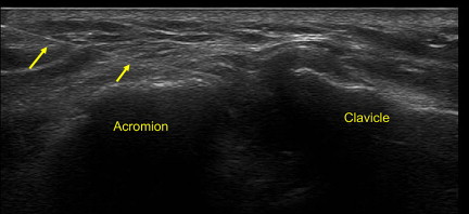
Although the AC is a superficial joint, there is an approximate 60% miss rate associated with blind joint injections. Therefore, US-guided injections provide a more accurate way to place therapeutic medication. The AC joint can be approached with the in-plane technique or out-of-plane technique. With the in-plane approach, it is advised to use a stand-off approach. A short-axis view of the joint and capsule is first obtained. A 25G needle is then placed in plane with the US probe into the capsule of the joint ( Fig. 13 ). This is followed by a small volume of anesthetic and corticosteroid, which can be seen filling the capsule or entering into the joint. Conversely, an out-of-plane technique can be used. A longitudinal view of the joint is first used. The borders of the joint are marked on the patient’s skin. The probe is then turned at 90° so that a short-axis view is obtained. A needle is entered underneath the probe out of plane between the two markers on the skin. The needle can then be identified entering into the intra-articular space of the AC joint.
Glenohumeral joint
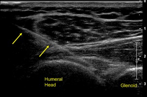
The glenohumeral joint is typically injected with a posterior lateral approach. Typically, a short-axis view is first obtained of the posterior joint. Next, a needle, typically of longer length, is placed obliquely under the probe with a lateral to medial trajectory. The needle is placed between the humeral head and glenoid where medication is injected into the joint ( Fig. 14 ). Although there are no studies examining the efficacy of glenohumeral joint injections with US guidance, there is a greater success rate with initial attempts when US guidance is used compared with fluoroscopically guided injections.
Biceps tendon sheath
The biceps tendon sheath can be injected with the arm placed in a supinated position while obtaining a short-axis view of the tendon. A small-gauge needle is placed in plane with the transducer into bicipital tendon sheath. As fluid is injected, a halo of hypoechoic fluid is seen filling around the biceps tendon, confirming placement of medication.
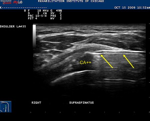
Calcific tendonitis
Calcific tendonitis is a known painful cause of shoulder pain and may contribute to impingement type symptoms. Aspiration of hydroxyapetite crystals along with subsequent subacromial bursa corticosteroid injection can provide substantial relief. This procedure is performed with a similar approach as a subacromial bursa injection. The calcific deposit is hyperechoic within the rotator cuff tendon and often is associated with acoustic shadowing. After adequate local anesthesia is obtained, a large-gauge needle, typically 18 to 20 G, is placed in plane with transducer into the calcific deposit ( Fig. 15 ). Smaller-gauge needles may also be effective. A 5- to 10-mL syringe filled with saline is used to repeatedly lavage the area under direct visualization. Oftentimes the chalky-appearing crystals, which are aspirated back into the syringe, settle out so it advisable to keep the syringe positioned so that the crystals are not inadvertently reinjected back into the patient. Lavage continues until no more chalky material is obtained. An alternate technique that avoids the accumulation of the crystals in the syringe is to use a two-needle technique. One syringe is used to inject fluid while the other is used to aspirate the fluid. If the calcifications are well formed and hard, they can be repeatedly probed with the needle tip in order to fragment it. Aspiration of these calcifications in nonrandomized studies leads to improved pain and functional outcomes.
Elbow
Lateral epicondyle injection
US-guided procedures for lateral epicondylosis typically involve obtaining a longitudinal view of the lateral epicondyle, radiocapitellar joint, and proximal wrist extensor mass while the elbow is placed in slight elbow flexion. Although not often in direct view, the lateral collateral ligament and the radial nerve should be located so as to avoid unnecessary injury. A needle is placed in plane under the transducer distally or proximally near the tendon origin or area of greatest symptoms. One study showed injection of corticosteroid using US guidance directly into the area of proximal wrist extensor tendon hyperemia seen with Doppler US provided significant short-term pain relief. There was no comparison made with blindly placed medication, however. US has been used to help guide many other novel treatments in cases of refractory lateral epicondylosis. The medial epicondylar structures are injected in a similar fashion although the medial epicondyle serves as the bony acoustic landmark.
Elbow joint
The elbow joint can be injected with the arm supported and the elbow placed into 90° of flexion. A longitudinal view is obtained of the posterior elbow joint. Next, a needle is placed in plane with the transducer under direct visualization entering the humeroulnar joint proximally to distally. If possible it is recommended to enter adjacent to the triceps tendon rather than through it. Effusions, if present, can also be aspirated from this location.
Wrist and Hand
Carpal tunnel/median nerve injection
Although there are several different approaches that may be used to inject the carpal tunnel, Smith and colleagues have described an ulnar approach. The wrist is supported in a slightly extended position. Next, a transverse view of the volar distal wrist is obtained using a high-frequency transducer. The median nerve is identified as a honeycomb fascicular superficial structure, exhibiting less anisotropy than nearby flexor tendons. A 27G needle is placed medially and superficially to the ulnar nerve and artery in plane with the transducer and gradually advanced toward the median nerve ( Fig. 16 ). Medication is injected superficially and deep to the nerve, theoretically creating a mechanical separation of the nerve away from adherent connective tissue, which may also relieve symptoms. Grassi and colleagues have shown that US-guided carpal tunnel corticosteroid injection leads to improvement of symptoms in a subset of rheumatoid patients with flexor tenosynovitis.
Abductor pollicis longus and extensor pollicis brevis tenosynovitis (de Quervain tenosynovitis)
The first compartment of the dorsal wrist is composed of the extensor pollicis brevis and abductor pollicis longus tendons. When present, tensosynovitis of these tendons can create pain in the dorsoradial aspect of the wrist. Injecting this area blindly has a known associated miss rate. In addition, there are intertendinous septa, which, if present, may theoretically limit the spread of medication. The combination of these factors may limit the effectiveness of therapeutic injections. Zingas and colleagues have shown that accurate placement of medication in this condition results in greater clinical improvement than blind injection.
Although the thumb extensor sheath can be injected with a longitudinal or short-axis view of the tendon, the transverse view is preferred having the needle entering the sheath while in plane with the transducer. Care should be taken in identifying and avoiding the superficial branch of the radial nerve. The use of stand-off gel enables the needle to be placed into the tendon sheath without traversing a large amount of subcutaneous tissue. Once within the tendon sheath, medication can then be injected, seen to surround the tendon and distending the tendon sheath ( Fig. 17 ). US-guided injection for chronic de Quervain tenosynovitis is safe and effective in reducing symptoms while preventing potential tendon injury and fat atrophy.
Carpometacarpal joint
The first carpometacarpal joint is the most common sight of osteoarthritis in the upper limb. Because it is relatively small joint associated with degenerative changes, injecting this joint blindly is associated with a relatively high miss rate. Injecting this joint is similar to the approaches used for the AC joint except appropriate tendon neurovascular structures should be identified with US before the injection.
Stenosing flexor tenosynovitis (trigger finger)
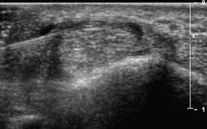
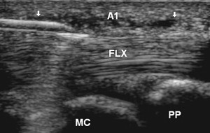
Stenosing tenosynovitis of a finger flexor, more commonly known as trigger finger, is typically due to abnormal thickening of the A1 pulley near the MCP joint. Studies have shown that accurate placement of corticosteroid under US guidance is associated with improved long-term outcomes. One technique used to inject this area with US involves obtaining a transverse view of the finger flexor and localizing the A1 pulley as a thin hypoechoic structure overlying the tendon. Alternatively, a longitudinal view may first be obtained of the pulley while the needle is placed in plane with the probe and corticosteroid injected ( Fig. 18 ).
Lower Limb-Hip
Hip joint
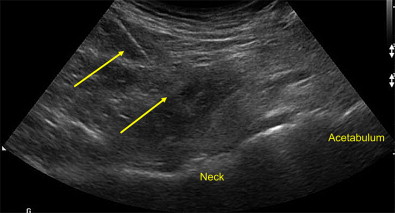
Blind injection of the femoroacetabular or hip joint is associated with a relatively high miss rate and potential injury to neurovascular structures. US guidance is an accurate and rapid way to place therapeutic medications into the hip joint, identifying neurovascular structures and avoiding ionizing radiation. To adequately visualize the bony landmarks of the hip joint, a low-frequency curvilinear probe may be necessary, especially in larger individuals. A relatively long spinal needle is placed in plane with the transducer from a distal to proximal approach into the anterior synovial recess ( Fig. 19 ). While injecting under direct visualization, medication can be seen dispersing away from the needle tip filling the joint. In uncontrolled trials using different US approaches, repeated viscosupplementation injections demonstrate significant improvement in visual analog scale and functional outcomes. In a controlled pilot study, patients treated with repeated corticosteroid injections into the hip compared with saline using US guidance experienced significant improvement during the study period, indicating a moderate clinical effect.
Piriformis
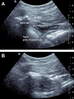
Piriformis syndrome can cause buttock pain and, because of its association with the sciatic nerve, can also create leg pain. In cases that are refractory to treatment, an injection into the piriformis and perisciatic area may provide therapeutic benefit. US has been shown to be a more accurate way to place medication into this structure than fluoroscopy. To perform a US-guided piriformis injection, patients are placed prone and, depending on body habitus, a linear or curvilinear transducer is placed horizontally over the posterior superior iliac spine. The transducer is moved inferiorly and slightly obliquely until the medial aspect of the transducer is located over the lateral sacrum and the marbled hypoechoic appearance of the gluteus maximus is seen running over the sacrum. A longitudinal view of the pririformis is identified as a small tapering muscle deep to gluteus maximus running caudally laterally from underneath the lateral sacrum attaching to the greater trochanter ( Fig. 20 A). The sciatic nerve, identified more distally, is followed proximally, most commonly running deep to the piriformis. A needle is placed medially and directed toward the piriformis laterally until the needle tip is seen puncturing the overlying sheath or advanced further into the muscle at which medication is injected (see Fig. 20 B). After this, the hip can be rotated several times encouraging the spread of the medication.
Related posts:
 Basic Appearance of Ultrasound Structures and Pitfalls
Ultrasonography of the Shoulder
Ultrasonography of the Hip and Lower Extremity
A Physiatrist’s Perspective on Musculoskeletal Ultrasound
Ultrasonography in Regenerative Injection (Prolotherapy) Using Dextrose, Platelet-rich Plasma, and Other Injectants
High-Frequency Ultrasound Guidance for Neurotoxin Injections
Basic Appearance of Ultrasound Structures and Pitfalls
Ultrasonography of the Shoulder
Ultrasonography of the Hip and Lower Extremity
A Physiatrist’s Perspective on Musculoskeletal Ultrasound
Ultrasonography in Regenerative Injection (Prolotherapy) Using Dextrose, Platelet-rich Plasma, and Other Injectants
High-Frequency Ultrasound Guidance for Neurotoxin Injections
Stay updated, free articles. Join our Telegram channel

Full access? Get Clinical Tree


