Special series of the shoulder
Shooting technique
Findings
Anteroposterior (AP)
Patient in the standing or supine position
Cassette is parallel to the coronal plane of the body
Beam is directed in a true AP direction to center of the coracoid
First choice radiography for pathologies in shoulder
Provides initial assessment of the glenohumeral joint, acromioclavicular joint, and distal clavicle pathologies
Grashey view (TRUE AP)
Patient is rotated posteriorly approximately 35–45° in the standing position
Beam is directed perpendicular to the cassette
Allows for better evaluation of the glenohumeral joint cartilage, joint space, joint congruity, and humeral head subluxation
Axillary view
Patient is placed in supine position and the shoulder is abducted at 90°
Beam is centered on the mid-glenohumeral joint and directed 15–30° toward the spine
Used for evaluating dislocations, subluxations of the humeral head, cartilage thickness, or bone Bankart lesions
West Point view
The patient is placed in the prone position with the arm abducted 90° and the patient’s forearm is pronated
Beam is centered at the glenohumeral joint tilted 15–25° superior and tilted 25° toward the spine
Anteroinferior glenoid rim and bone Bankart lesions are clearly seen with this view
Scapular Y view
Patient in standing or supine position
Shoulder is rotated 45° anteriorly, arm is dropped near the body, and comes over the scapula
Beam is directed from posterior to anterior
Used for assessment of anterior and posterior shoulder dislocations, Hill–Sachs lesions, acromion, and subacromial osteophytes
Rockwood view
Patient in standing or supine position
Cassette is parallel to the coronal plane of the body
X-ray beams come tilted 30° caudally to the shoulder
Provides preferable visualization of Acromion and subacromial space
Preferred at impingement syndrome to evaluate the acromion and subacromial space
Supraspinatus outlet view
Patient in standing or supine position; the shoulder is rotated 45° anteriorly; the arm is dropped near the body and comes over the scapula
X-ray is perpendicular to scapular body and parallel to joint surface of glenoid. Beams are tilted 10–15° caudally
Provides preferable visualization of the acromion and subacromial space
Used for exhibiting the acromial and subacromial pathologies
Stryker notch view
Patient is placed in supine position
Arm is externally rotated and abducted. The patient’s hand is located under his head; the elbow looks to plafond
X-ray is directed to the coracoid and angled 10° cephalic
Used for assessment of posterolateral aspect of the humeral head, Hill–Sachs deformity, or flattening of the posterolateral humeral head
The most sensitive radiography detecting the Hill–Sachs lesion on the humeral head
Serendipity view: The patient is placed in a supine position. While x-ray beams are giving with 40° cephalic and caudal slope, anteroposterior radiographs of the sternoclavicular joint are taken. The presence of subluxation or dislocation can be detected by evaluating the relative position of the clavicle to the sternum. In cases that a definitive diagnosis cannot be found, computed tomography is utilized.
AP view of the shoulder: It is the first-line and most useful imaging study in the evaluation of shoulder pathologies that may be taken in standing or supine position. AP radiography is important for evaluating fractures or dislocations in trauma cases and evaluating calcific tendonitis or bursitis and AC joint arthritis in the cases of chronic shoulder pain and provides complete visualization of glenohumeral joint, acromioclavicular joint, distal clavicle, acromion, and the proximal part of the humerus. While film cassette is placed parallel to the broad surface of the scapula, x-ray beams should point to the centers of the coracoid. Because of the glenoid articular surface has 35–40° anteversion, the glenoid and humeral head overlap on the AP radiograph [1]. Three different AP projections can be obtained, with the arm in external rotation, internal rotation, or neutral position. Tuberculum minus and tuberculum majus are seen on the lateral side; humeral head that has resemblance to an Indian ax is seen on the medial side on AP radiography that is taken with the arm in external rotation. Anatomic neck is seen between the tubercula (majus and minus) and the humeral head. The average interval between the humeral head and the acromion is 7 mm. The humeral head is seen as a rounded shape similar to the ice cream cone on AP radiographs, which is taken with the arm in internal rotation. Shoulder pain may be reflected from lung pathology, so the evaluation of the lungs in the same radiography will be beneficial.
Rockwood view: It is a modified AP radiography that is preferred at impingement syndrome to evaluate the acromion and subacromial space. While film cassette is placed parallel to the broad surface of the scapula, x-ray beams come tilted 30° caudally to the shoulder. The acromion and subacromial space can be clearly visualized with this view. Inferior border of the acromion must be over the line of the inferior border of clavicle; otherwise it might be considered as osteophyte or exositozis of the acromion.
Grashey view: The true AP radiography of the shoulder. It provides tangential view of the glenohumeral joint and allows excellent evaluation of the glenohumeral cartilage space and the proximal humerus. Patient is rotated posteriorly or x-ray device is turned lateral to eliminate of glenoid’s anterior inclination [2] (Fig. 7.1). In this way, overlapping of the humeral head and glenoid is prevented at AP radiography. The humeral head, cartilage of glenoid, glenohumeral joint space, joint congruence, and joint subluxation can be evaluated more clearly on this radiography [3]. Image quality can be decreased because of the soft tissue thickness.
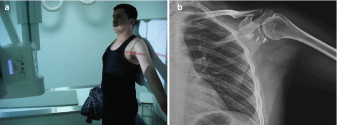

Fig. 7.1
(a) Position of the patient and x-ray during the Grashey radiography. (b) Image of Grashey radiography
Axillary view: It is a tangential view of the glenohumeral joint. It is used for assessment of subluxation or dislocation of the humeral head. It is also used for detecting bone Bankart lesion involving the anterior glenoid rim. Patient is placed in supine position and the shoulder is abducted at 90°. X-ray beams are centered on the glenohumeral joint and directed 15–30° toward the spine (Fig. 7.2).
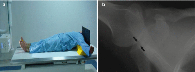

Fig. 7.2
(a) Position of the patient and x-ray device during the axillary radiography. (b) Image of axillary radiography. Arrows show congruousness of glenohumeral joint
West Point view: It is the modification of axillary radiography that allows excellent evaluation of the anteroinferior border of the glenoid [4]. Bone Bankart lesion of the anterior glenoid rim is detected easily with this view [5]. Patient is in prone position and the shoulder is abducted at 90°; the arm is located on a pillow. The forearm is pronated. X-ray beams are centered and glenohumeral joint tilted 15–25° superiorly and tilted 25° toward the spine (Fig. 7.3). This view can be painful in patients with acute shoulder injury.
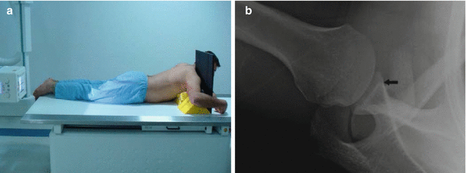

Fig. 7.3
(a) Position of the patient and x-ray device during the West Point radiography. (b) Image of west point radiography. Arrows show location of Bone Bankart Lesion
Scapular Y view: It is used for assessment of anterior and posterior shoulder dislocations. Position of patient and shooting of x-ray are easier than axillary radiography in acute traumas. There is no difference between scapular Y radiography and axillary radiography for detecting the pathologies [6]. However, scapular Y radiography is also useful in Hill–Sachs lesions. Scapular Y radiography proves scapula, acromion, and coracoid pathologies. Stem of “Y” is made by the scapula’s body and legs. Acromion and coracoids composed legs of “Y.” It is obtained in supine position or standing position. While the shoulder is rotated 45° anteriorly, x-ray beams are directed from posterior to anterior (Fig. 7.4). The arm is dropped near the body and come over the scapula. The humeral head is centralized on the center of Y. If the humeral head is anteriorly, this condition is called anterior dislocation. If it is posteriorly, this condition is called posterior dislocation. Fractures of the scapula (when shooting arm is positioned anteriorly), acromion, and coracoid process can also be detected with this view.
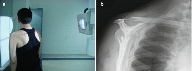

Fig. 7.4
Scapular Y radiography. (a) Position of the patient and x-ray device during the scapular Y radiography. (b) Image of scapular Y radiography
Supraspinatus outlet view: It is used for exhibiting the acromial and subacromial pathologies. Scapular Y radiography is more useful for detecting the types of acromion, and subacromial osteophytes may cause impingement. Shooting technique is similar to scapular Y radiography, but x-ray beams are tilted 10–15° caudally. X-ray is perpendicular to scapular body and parallel to joint surface of the glenoid.
Stryker notch view: Patient is placed in supine position and the arm is externally rotated and abducted. The patient’s hand is located under his head; the elbow looks to plafond. X-ray is directed to the coracoid and angled 10° cephalic. It is used for assessment of posterolateral aspect of the humeral head and Hill–Sachs deformity or flattening of the posterolateral humeral head. It is the most sensitive radiography detecting the Hill–Sachs lesion on the humeral head [4].
Malalignments
Fractures
It is important to define the fracture and localize part of fracture in the proximal humerus. In 1970, Neer classified these fractures into four groups. The fracture segments are the humeral head, humeral shaft, tuberculum majus, and tuberculum minus. More than 1 cm separation and more than 45° angulation is defined as displaced. Angulation between the shaft and head has to be evaluated on frontal and lateral plains at surgical neck fractures. Displacement of tubercula could be evaluated on axillary radiography, but patient could have serious pain. Because of this angulation of fractures, the humeral neck on sagittal plain can be evaluated with good dosage transthoracic radiography.
Dislocations
The most of the dislocations of the patients that come to emergency room occurred in shoulders. Anterior (95 %), posterior (5 %), and inferior (subglenoid luxatio erecta 0.5 %) are three types of dislocation. Anterior dislocations usually occurred because of trauma. Humeral head slides anteromedial and below to the glenoid fossa. This can be evaluated with AP radiography, but the axillary view or the scapular Y view is very specific for dislocations. Dislocation may cause recurrence in younger patients. Because of recurrence dislocation, Bankart lesion on anteroinferior rim of the glenoid and Hill–Sachs lesion on the humeral head may occur. It is not important clinically if there is less than 20 % of articular surface of the glenoid. In addition, tuberculum majus fracture may occur during the dislocation. AP radiography is usually enough for diagnosis, but axillary and scapular Y radiography can be taken for confirmation. Hill–Sachs, which occurs during recurrent anterior dislocation, is osteochondral lesion on posterosuperior of the humeral head. Striker notch radiography is the best option to demonstrate Hill–Sachs lesions.
Posterior dislocations are caused by epileptic seizures or electric shock. Most of them are bilateral. Stronger internal rotator muscle contraction causes this situation. The mechanism of posterior shoulder dislocation is thought to be unequal muscle contraction with the internal rotators of the shoulder, causing the humeral head to move superiorly and posteriorly. Osteochondral fracture on anterior part of the humeral head may occur that is called reverse Hill–Sachs lesion, and posterior glenoid rim fracture may occur that is called reverse Bankart lesion. AP radiography is not usually enough and can cause missout. Axillary radiography makes diagnosis at 100 % [7]. If there is pain, scapular Y radiography or computerized tomography can be a choice.
Luxatio erecta is named as inferior or subglenoid dislocations. Arm is hyperabducted and cannot be pulled inferior. It may occur after falling in hyperabduction position. Neurological injury could occur, especially in axillary nerve. AP radiography is enough for diagnosis.
Situations That Change Density
Density changing in the humeral head is caused by chondral lesions and tumors. Most three situations that cause chondral lesions are trauma, steroids, and sickle cell anemia. Sclerosis, collapse, fragmentation, and degenerative changes can be seen in avascular necrosis according to the stage.
Synovial chondromatosis may result from primary or secondary to chondral lesions. In primary, multiple cartilaginous nodules are formed because of synovial membrane proliferation and metaplasia. Tumor lesions can be radiolucent or radiodense.
Situations That Damage the Joint Cartilage and Articular Distance
The most causes are rheumatoid arthritis and osteoarthritis. Diffuse osteopenia, localized erosion, and uniform narrowing on articular space occur in rheumatoid arthritis. Primary osteoarthritis is a rare situation in the shoulder, because it is not a load-bearing joint. Generally, it is secondary to trauma, systemic arthritis, chronic rotator cuff tears, congenital malformations, and acromegaly.
Soft Tissue Lesions
(a)
Calcific tendinitis or calcific bursitis (hydroxyapatite storage disease) is a typical example. At most, it occurs around the shoulder joint. In more than half of the cases, supraspinatus tendon is involved. Infraspinatus and teres minor tendinitis are seen well on internal rotation because of posterior location. Subscapularis tendinitis is seen anteriorly. It could be symptomatic or asymptomatic.
(b)
Impingement syndrome: This is impinging of supraspinatus tendon, subacromial–subdeltoid bursae, and biceps tendon between the humeral head and acromion. It is diagnosed generally by clinical and subacromial injection test. For the etiology, radiography must be taken. Acromion could be flat, curved, or hooked. The angle between lower anterior and posterior surfaces of acromion is acromion angle. It helps to determine the shape of the acromion and the amount of resection while performing acromioplasty. Os acromiale, type 3 acromion, acromial osteophyte, and acromioclavicular degeneration must be identified. Supraspinatus outlet radiography is the most beneficial technic. The Rockwood radiography, which is an angled frontal radiography, provides frontal osteophyte view without any overlapping on the acromion. Cortical thickening or subcortical sclerosis on the tuberculum majus has lower specificity at diagnosis of rotator cuff lesions. But the specificity of subchondral cysts is higher.
(c)
Rotator cuff tears: Direct radiography is usually normal on rotator cuff tears. Glenohumeral distance decreases below 2 mm in hyperabducted radiographies. Loosening of convexity and flattening of supraspinatus muscle at outlet radiography must be thought rotator cuff tears. Lower density layer on normal muscle density must be thought of as fatty degeneration. Acromiohumeral distance decreases below 7 mm because the strength of rotator cuff that detrudes the humeral head is weak according to the strength of the deltoid that elevates the humeral head. At late stages of rotator cuff tears is the rotator cuff arthropathy named as a Milwaukee shoulder syndrome.
Also it is high density because of calcium pyrophosphate dihydrate storage disease, and synovial chondromatosis must not be overlooked.
Radiological Evaluation of the Elbow
The elbow joint is very complex that is formed by the distal humerus and proximal ulna and radius. The types of humeroulnar joint are complex hinge, and other joints of the elbow (radiohumeral and the radioulnar joints) are pivot.
Anatomic structures around the elbow are the distal humerus, olecranon, coronoid, and radial head. The distal humerus consists of capitellum, trochlea, medial and lateral condyle, and olecranon fossa. There is a 10–12° of valgus angle at anteroposterior plain of the elbow. Distal humerus has 30° anterior tilt at lateral plain. These complex articulations and structures can be evaluated when well-positioned radiographs are obtained.
Appearances of children and adult elbow views are different from each other. In addition, appearance of children elbow view depends on the age of children, because the elbow has many different ossification centers which reveal at different times. So elbow radiographs must be taken bilaterally and compared to noninjured extremity in traumatized patient. Anteroposterior, lateral, and radial head radiographies are routinely used at trauma series. Traction radiographies could be needed at multifragmental and burst fractures [8].
Elbow AP view: AP radiography must be taken at full extension of the elbow and supination of the forearm. X-ray is directed vertical to the joint. The condyles, capitellum, trochlea, radial head, and elbow carry angle that can be assessed on AP radiography [9]. In the proper radiography, radiohumeral and humeroulnar joints and the medial and lateral humeral epicondyles should be clearly shown. The radial head and radial tuberosity should be minimally superimposed on the ulna. If there is flexion contracture, two AP radiographs must be taken. X-ray beams parallel to the forearm in one and humerus in another.
Structures evaluated on elbow AP view:
Radius neck–shaft angle: the angle is between the radial neck and radial diaphysis. The normal value is 15° [10].
Joint surface angle: the angle is between humeral shaft and the line from distal border of the trochlea and capitellum. The normal values are between 82 and 84°.
Elbow carry angle: the elbow is curved laterally when fully extended and supinated. The angle between the center of the arm and forearm is called as a “carry angle.” It is used at fractures of the distal humerus and elbow. It is important to evaluate carry angles bilaterally [11]. It is the angle between the line parallel to the humerus and ulna at radiographs. Valgus of trochlear notch and valgus of distal humeral make carry angle [12]. Positive values show valgus angulation. The elbow carry angle increases at adult ages and greater at the dominant hand [13]. Values of carry angles are variable at all ages, in women 11.8° and in men 6.9°. Carry angle is same before puberty in girls and boys, but it increases after puberty in girls, so some authors say it is one of the secondary sex characters [14].
Baumann angle: it is used to evaluate pediatric humeral distal fractures on coronal plain. Baumann angle is used especially in Gartland type 2 fractures which treatment is not clear. This angle best shows alignment of distal humerus on coronal plane [15]. It is the angle between long axis of the humerus and line from lateral condylar physis. Normal value of the angle is 75–80° [16]. There is discussion about the true Baumann angle that has three variants [13].
Trochlear notch angle: The angle is between medial and lateral faces of the trochlea.
Elbow lateral view: It must be taken with abducted shoulder at 90° and flexed elbow at 90° and up-righted thumb, while ulnar face of the forearm is on the table. X-ray must be centered on the radial head. Posterior aspects of supracondylar region must be overlapped for true lateral radiography of the elbow [17]. Olecranon, coronoid, radial head, anterior fat pad, posterior fat pad, anterior humeral line, and radiocapitellar line are evaluated.
Anterior humerocapitellar line: This line that draws along anterior of the distal humerus should pass through middle one third of the capitellum. This measurement is used for treatment of supracondylar fractures in children.
Radiocapitellar line: This line shows the relationship between radial head and capitellum and should pass through the center of the radius neck and middle one third part of capitellum. In dislocation of the radius, this line will not pass through the center of the capitellum.
Anterior angulation of distal humerus joint line: The distal end of the humerus is angled 30° anteriorly.
Olecranon–coronoid angle: This line connects the longitudinal axis of the ulna with the end point of the olecranon and coronoid.
The presence of fat pad: There are anterior and posterior fat pads in the elbow joint. Fat pads consist of tightly packed and fibrous tissue surrounded by lipid cells [18]. Fat pad tissue is intracapsular but extrasynovial. Although the anterior fat pad can be seen in standard lateral radiographs, posterior fat pad could not be seen [19]. Effusions of elbow joint raise both of the anterior and posterior fat pad and make them visible on lateral radiographs. A lifted posterior fat pad demonstrates a hidden intracapsular fracture [20].
Radius head–capitellum view: This radiograph is a modification of lateral elbow radiography. X-ray beams are directed to the radius head tilted 45°. Unlike the lateral radiographs, humeroradial and humeroulnar joints can be displayed better [21]. It is significant for exhibiting posterior half fracture of radial head.
Internal oblique view of the elbow: This radiograph shows the medial epicondyle, trochlear notch, and coronoid tubercle of the ulna. The forearm is pronated at 45°. X-ray beams come perpendicular and centered 2 cm below the medial epicondyle.
External oblique radiography of the elbow: It is used for assessment of the capitellum and radial head. The forearm is supinated at 45°. X-ray beams come perpendicular to the elbow.
Capitellum fractures are best seen in lateral radiographs. There is a double-bubble sign in type 4 capitellum fractures (capitellum fractures with trochlear fractures). Lateral compression can cause Panner disease of the elbow, capitellum OCD, radial head OCD, and angular deformity in the radial head. Fissures, fragmentations, and irregularity occur in early stage, and then reossification and resolution occur in late stage on lateral radiographs [22].
Coronoid bone is very important for elbow stability. It is important to evaluate magnitude of fracture fragment for classification of coronoid fractures. Larger than 50 % of the coronoid fracture fragment leads to instability. Usually, lateral elbow radiography is enough for evaluation. Also coronoid fracture fragment involving the inner or the outer edge is important for determining the direction of instability. Because of the difficulty to detect this situation in lateral elbow radiography, computed tomography can be used.
Usually AP and lateral radiographs of the elbow are enough for diagnosing radial head fractures. However, putting forward the amount of fracture fragmentation and positions of fractured pieces and to view the articular surface clearly, computed tomography would be useful. It should be also known that in children, radial neck fractures occur more likely rather than the radial head fractures.
Elbow dislocations are usually posterior in direction and determined by lateral radiographs. After reduction, to be sure of reduction and to clearly reveal accompanied fractures, AP and lateral radiographs should be taken again. While coronoid and radial head fractures accompany elbow dislocations in adults, medial epicondyle fractures accompany in children (Table 7.2).
Table 7.2
Common elbow views, technique, and findings
Radiographs | Shooting technique | Findings |
|---|---|---|
Anteroposterior (AP) | Patient in the upright or supine position The elbow should be fully extended with the forearm supinated Cassette is parallel to the coronal plane of the body X-ray beam is directed perpendicular to the cassette | Allowing optimal visualization of the medial and lateral epicondyles, radiocapitellar joint, and estimation of the: Carrying angle Radius neck–shaft angle Joint surface angle Elbow carry angle Baumann angle Trochlear notch angle |
Elbow lateral radiography | Patient in the upright or supine position The elbow in 90° of flexion and the forearm in neutral (thumb up) position X-ray must be centered on the radial head | Allows for evaluation of: Olecranon Coronoid Radial head Anterior fat pad Posterior fat pad Anterior humeral line Radiocapitellar line Elbow dislocation |
Radius head–capitellum radiograph | Modification of lateral elbow radiograph The x-ray tube directed 45° toward the radius head | Used for better display of: Humeroradial joints Humeroulnar joints Posterior half fractures of radial head |
Internal oblique radiography of the elbow | Patient in the upright or supine position The elbow fully extended; shoulder and elbow on the same horizontal plane The hand is pronated and forearm is aligned to long axis of IR The forearm is rotated medially so the distal humerus and the anterior surface of the elbow joint is 45° to IR (palpate epicondyles to determine rotation) | Used for assessment of: Medial epicondyle Coronoid tubercle of the ulna |
External oblique radiography of the elbow | Patient in the upright or supine position Arm fully extended; shoulder and elbow on the same horizontal plane The hand is supinated and forearm is aligned to long axis of IR The forearm is rotated laterally so the distal humerus and the anterior surface of elbow joint is 45° to IR (palpate epicondyles to determine rotation) | Gives better information about: Capitellum Radial head |
Radiological Evaluation of the Hand and Wrist
Standard radiographs included anteroposterior, lateral, and oblique views of the wrist and are sufficient for the determination of most of the pathology occurred with or without trauma. Additional radiographs may include radial or ulnar deviation views, carpal tunnel view, special scaphoid views, and stress views.
AP View of the Wrist
Posteroanterior view is taken with the shoulder abducted 90° and elbow flexed 90° (in the same level with the shoulder). So palmar face of the hand is placed flat on the cassette with the forearm rotated internally.
Distal joint surfaces of the radius and ulna, radial inclination, radial length, and distal radioulnar joint compliance (ulnar variance) are evaluated. In addition to carpal bones, intercarpal joints and radiocarpal joints can be examined.
Joint surfaces of the radius and ulna: Load transfer of the wrist joint occurs with 80 % by radius joint surface and 20 % by ulnar joint surface. Distal radius fractures usually involve the joint surface. More than 1 mm stepping on the joint surface may be able to lead wrist degeneration. If radiography is insufficient to evaluate stepping on the joint surface, CT could be useful. Distal ulna fractures, mostly styloid, may accompany to distal radial fractures.
Radial inclination: The angle between the transverse line of distal radius joint surface and the line that draws from the ulnar corner of the radius to the radial styloid gives the radial inclination (Fig. 7.5). Normal value of inclination is between 22 and 23°. After distal radius fractures, radial inclination decreases. Seventeen to eighteen degrees can be acceptable for treatment.
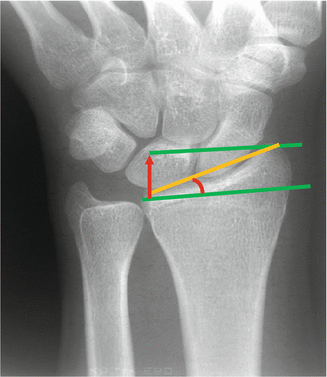

Fig. 7.5
AP view of the wrist
Radial length: This is distance between the articular surface and the radial styloid (Fig. 7.5). Normal value of length is between 11 and 12 mm, but it reduces in distal radius fractures. Nine millimeter can be acceptable for treatment.
Distal radioulnar joint compliance: Normally, the distal radius joint and the distal ulna joint surfaces are in the same line. If the ulnar surface is above the radial surface (in the same time ulnocarpal distance >0.9 mm), it is named as positive ulnar variance. If the ulnar surface is below the radial surface (in the same time ulna-carpal distance <0.9 mm), it is named as negative ulnar variance.
Carpal bones: The scaphoid, lunatum, triquetrum, and pisiform bones create proximal row, and the trapezium, trapezoideum, capitatum, and hamatum create distal row of the carpal bones. Scaphoid and lunate bones articulate with scaphoid and lunate fossa on the distal radius joint surface. Distal ulna establishes a relationship with carpal bones through triangular fibrocartilaginous complex (TFCC).
Lateral View of the Wrist
Lateral view is taken with the shoulder abducted 90° and elbow flexed 90° in the same level. Then the wrist is placed on cassette with the forearm in neutral position. The long axis of the third metacarpal should be parallel with the long axis of the radius on a true lateral view of a normal wrist. In addition, pisiform should appear directly over the dorsal pole of the scaphoid on a true lateral view.
Volar tilt of distal radius joint, distal radioulnar joint, and radiocarpal joint can be evaluated.
Tilt of the distal radius joint surface: The distal radial tilt accounts for the angle between a line along the distal radial articular surface and the midshaft line of the radius. The distal radius joint surface has a 10° volar tilt on the lateral plane normally. Dorsal angulations occur usually in distal radius fractures. Acceptable volar tilt ranges 2–20° after reduction.
Distal radioulnar joint: Distal radioulnar instability can occur after trauma. Dorsal subluxation of the ulna usually may appear on lateral plane. Especially in the Galeazzi fractures and Essex–Lopresti injuries, care should be taken about distal radioulnar instability.
Carpal Instabilities
The radius, lunatum, capitatum, and long axis of the third metacarpal are at the same line in a normal lateral wrist radiography [23]. This line is broken in the presence of carpal instability and become like a “Z”-shaped line. There is a 30–60° angle between long axis of the scaphoid and the line passes through middle of the lunatum. There is a less than 10–20° angulation between the capitatum and lunatum.
There is less than 3 mm gap between scaphoid, lunatum, and triquetrum bones that create proximal row in the AP view. The gap between scaphoid and lunatum expands in the case of scapholunate ligament injury, and the gap between lunatum and triquetrum expands in the case of lunotriquetral ligament injury.
Ligaments around the lunatum generate little ring that is named as “small arc” on the AP view. A break of this arc demonstrates one or more ligament injury of this ring. The big ring that generated from the bones around the lunatum is named as “big arc.” A break of this arc demonstrates one or more fractures of these bones. In addition, three different arcs were described by Gilula on the AP radiograph [24]. Proximal cortexes of the scaphoid, lunatum, and triquetrum generate “first arc,” distal cortexes of same bones generate “second arc,” and proximal cortexes of capitate and hamatum generate “third arc.” These arcs that have shown normal anatomic structure are broken down in carpal instabilities.
Carpal instabilities, which occurred with proximal row bones separation, are called as dissociative carpal instabilities. These pathologies are caused by ruptures of intrinsic ligaments between proximal row bones. These consist of scapholunate instability, lunotriquetral instability, and perilunate dislocation. Instabilities without separation of proximal row bones are called as non-dissociative carpal instabilities. These pathologies occur with injuries of the extrinsic radiocarpal ligament.
Carpal instabilities are also classified as static and dynamic instabilities. Static instability is carpal malalignment in a fixed position and diagnosed by PA and lateral wrist views in a stable position. Dynamic instability occurs with physical maneuvers and revealed with stress radiographs. While dynamic instabilities are only formed by the dorsal scapholunate ligament injury, static instabilities occurred by complete injury of the scapholunate ligament with palmar radiocarpal ligament injury. Static instabilities can be diagnosed easily in AP and lateral radiographs taken in stable position. While pathologies in dynamic instabilities can’t be observed in the radiographs of stable position, they can reveal in dynamic and stress radiographs. These dynamic radiographs are taken in flexion, extension, ulnar, and radial deviation. Stress radiographs are taken in fist-clenched position.
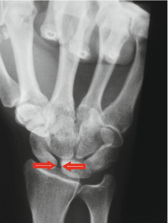
Scapholunate Instability: This instability occurs with scapholunate ligament injury. The scaphoid comes to more vertical position on coronal plane and comes to more flexion position on sagittal plane. The lunatum comes to extension position and tilts dorsally on sagittal plane. This condition is known as dorsal intercalated segment instability (DISI) [25]. Scapholunate gap is more than 3 mm on AP wrist view in this instability. This is called as Terry Thomas or Dave Letterman sign (Fig. 7.6). Superposition occurs in distal edge of the scaphoid with its rotation on own long axis and it seems like shortened. This sign is named as “ring sign.” Also the distance between distal end of the scaphoid and proximal end of scaphoid is less than 7 mm. The angle between the scaphoid and lunatum is more than 70°, the angle between lunatum and capitate is more than 10–20°, and the angle between lunatum and long axis of the radius is more than 10° in lateral radiography.
 < div class='tao-gold-member'>


Only gold members can continue reading. Log In or Register to continue
Stay updated, free articles. Join our Telegram channel

Full access? Get Clinical Tree


