The Polished Tapered Cemented Stem
Hussain Anthony Kazi
Jonathan R. Howell
INTRODUCTION
Since the advent, in the 1960s, of total hip replacement with cemented fixation, some designs have proven successful in the long term whereas others have not (1,2). There are two key principles to achieving long-term fixation with a cemented hip replacement, and both of these will be addressed in this chapter. Firstly, a surgeon should use a cemented stem that is designed to accommodate the properties of surgical cement, and secondly, the hip replacement should be performed with attention to detail, using a contemporary cementing technique.
Although in common parlance, use of the term “cement” to describe polymethylmethacrylate (PMMA) polymer is perhaps unfortunate because it evokes comparison with the inert grout used by the construction industry. In truth, PMMA polymer is a dynamic, viscoelastic material that exhibits important long-term properties (3) and these must be accounted for in the design of a cemented stem if long-term fixation is to be achieved. Most importantly, cement will slowly change shape over time if subjected to a sustained force, in a process known as creep, and the geometry of some stems is designed to allow for creep while others are not. Broadly speaking, cemented stems fall into two main categories, these being composite beam (sometimes referred to as shape-closed) stems and taper-slip (also known as force-closed) designs (4,5).
Taper-slip (force-closed) stems have a highly polished surface and are not bound to the PMMA polymer. They share common features in addition to their surface finish, being devoid of a collar and tapered in shape. As load is applied to these stems, they engage with the cement as a taper, and fixation is achieved by a balance of forces (6,7,8), just as it is in other scenarios where the common engineering concept of the taper is employed. The unique feature of this form of fixation is subsidence of these stems into the cement mantle over small distances. Studies using radiostereometric analysis (RSA) have shown that taper-slip stems migrate in the first year and then settle over time, with reported movement being 0.7 mm at 2 years and 1.3 mm at 10 years (8). Such subsidence is desirable and necessary for these types of stems to engage as a taper for long-term fixation. Many designs incorporate use of a hollow distal centralizer that provides a space below the stem tip into which the stem may subside to a stable position, without creating excess stress at the distal cement mantle (9).
Subsidence of taper-slip designs seems to have an additional benefit, in that it makes them more resistant to torsional forces and therefore more rotationally stable. Studies comparing taper-slip and composite beam stems (10) have shown that the latter also migrate distally, albeit over smaller distances than do taper-slip stems.
Taper-slip cemented stem designs differ from so-called composite beam implants. In the composite beam concept, the stem surface is rough or contoured to allow interdigitation of the PMMA
polymer and the stem surface, with the expectation that the stem will be rigidly bound to the cement. In this concept, stems may be described as “bonded” and such fixation will be intolerant of any micromotion at the stem-cement interface. Indeed, such micromotion has been shown to initiate a damaging cycle of events in which wear occurs between the stem and cement that eventually leads to loss of stem fixation (debonding) and aseptic loosening (11,12).
polymer and the stem surface, with the expectation that the stem will be rigidly bound to the cement. In this concept, stems may be described as “bonded” and such fixation will be intolerant of any micromotion at the stem-cement interface. Indeed, such micromotion has been shown to initiate a damaging cycle of events in which wear occurs between the stem and cement that eventually leads to loss of stem fixation (debonding) and aseptic loosening (11,12).
An example of the taper-slip design is the Exeter hip, designed in 1969 and first implanted in 1970 (13,14). Evidence from multiple centers and joint registries shows that this stem—and others like it—have given good results, in terms of aseptic loosening and revision rates (see literature review). Moreover, the technique offers two distinct significant advantages over most cementless designs, namely, the ease of anatomic restoration at the primary procedure and modularity at any subsequent operations.
Anatomic restoration is facilitated by the combination of features inherent in such stem designs, being as they are cemented, collarless, and available in a range of different sizes and offset. This means that a surgeon may select the appropriate offset to match the needs of the patient and then the stem size to match the dimensions of the femoral canal and finally may insert the stem into the cement to a depth that is entirely under the surgeon’s control and that will restore the correct leg length. Patients with high offset and narrow canals (typically young males) are accommodated as easily as are patients with capacious canals and low offset (typically older females).
Modularity at revision procedures is a valuable advantage to the surgeon conferred by these stems and is a consequence of their polished, tapered geometry and the associated taper-slip fixation. Exposure of the hip during a revision is facilitated by stem removal achieved by clearing the cement over the stem shoulder after which the stem can be tapped out of the cement mantle to allow access to the acetabular component. At the end of the revision operation, the same size or a smaller stem can be recemented into the old cement mantle without compromising the cement-bone interface and without the need to remove the well-fixed cement mantle.
As already discussed, the best long-term results will be produced by the combination of a proven stem design with a modern cementing technique. The aim of the surgical technique is to create close contact between cement and living bone (osseointegration (15)), without an intervening cellular layer, and this can only be achieved through meticulous surgical technique. Initial fixation is ensured by adequate bone preparation prior to the application of cement—it is important to leave strong trabecular bone in the proximal femur and to clean it well with the use of a pressurized lavage system. After retrograde filling of the plugged canal with PMMA polymer, pressurization of the PMMA is maintained prior to, during, and after insertion of stem until the polymer has completely cured. The techniques to achieve this are described below.
INDICATIONS FOR THE USE OF A CEMENTED STEM AT PRIMARY ARTHROPLASTY
Cemented femoral stems may be considered for any patient who requires a hip arthroplasty, but in choosing a stem for use, the surgeon should be aware that force-closed or taper-slip designs have generally given better results than shape-closed implants (4). There is no limitation to the age or diagnoses that may be suitable for cemented stem fixation, and in complex cases where there is distortion of the anatomy, femoral shortening procedures and derotation osteotomies can be carried out. After fixation of the osteotomy, the endosteal aspect of the osteotomy site should be impaction-grafted with autogenous bone chips to protect the osteotomy from cement intrusion during cement pressurization. For cases of displaced fractures of the femoral neck, cemented hemiarthroplasties or cemented femoral components in total hip replacements are indicated. There is a further advantage to using cement for fixation in cases of previous septic arthritis of the hip, since the cement can be loaded with appropriate antibiotic to reduce the risk of recrudescence of infection.
CONTRAINDICATIONS
There are no specific contraindications to the use of cement fixation in any patient for whom a hip arthroplasty is indicated.
PREOPERATIVE PREPARATION/PLANNING
Preoperative planning is an essential part of the operation and helps the surgeon predict the size, offset, and depth of insertion of the femoral prosthesis. Templating can be performed on traditional films or on digitized PACS (picture archiving and communication software) films using appropriate software, but it is important to ensure that the magnification of the radiograph is known and corrected for. The true offset is shown when the radiograph is taken with the lower limb internally rotated by approximately 15 degrees.
For templating of conventional radiographs:
Place the concentric rings on the templates centrally within the femoral head to locate and mark the femoral center of rotation.
The desired offset of the stem is then identified. The templates are placed on the radiographs with the stem in the middle of the femoral canal. The offset that reproduces the patient’s anatomy (center of prosthetic head overlying or closest to the center of the femoral head) is chosen (Fig. 14-1).
If the patient’s offset is between the prosthetic offset ranges available, the series of stems with the closest offset is chosen, and plus or minus heads can be then used to fine-tune the offset.
The stem size is identified by sequentially using templates with the femoral head and prosthetic head aligned. The stem size that will produce a 2 to 3 mm of cement mantle is chosen.
Leg length is controlled by the depth of insertion of the implant, and it is therefore independent of the choice of stem size and offset. The template is placed overlying the radiograph with the prosthetic head over the femoral center of rotation, and the stem centered in the canal. The outline of the neck, shoulder, and the stem is marked on the radiograph. The distance between tip of trochanter and shoulder of prosthesis is marked and noted. This insertion level will reproduce the patient’s anatomy and will achieve the correct leg length (16) (Fig. 14-2).
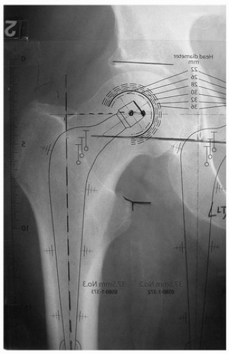 FIGURE 14-1 Radiograph with stem template overlying. Note adequate offset and cement mantle. |
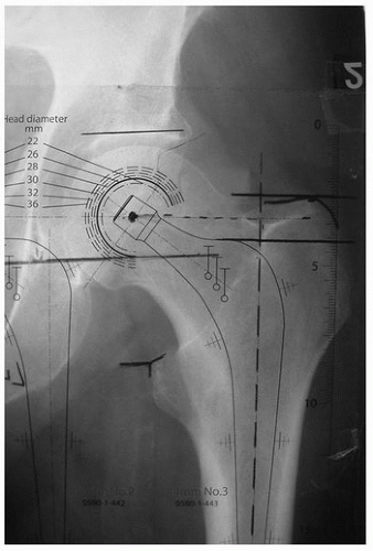 FIGURE 14-2 Distance from the shoulder of the prosthesis to the tip of the greater trochanter is marked. |
OPERATIVE TECHNIQUE
The longevity of the hip replacement depends on the surgeon establishing adequate initial mechanical interlock between the implant and the bone. With cemented stems, a satisfactory interface is achieved by creating a “closed cavity” and then using contemporary cementing techniques to introduce and pressurize cement. By applying pressure on cement from the time of initial injection until polymerization is complete, good cement intrusion into bone is assured and blood is prevented from accumulating at the interface (17,18,19).
Surgical Steps
The femur can be approached and prepared for cementing by any of the routine surgical exposures of the hip. In the operative technique described below, the posterior approach is used.
Femoral Neck Cut
Because the stem is collarless and the stem depth of insertion is flexible, the level of the neck cut is not critical with this type of stem. However, the resection line usually runs from a point midway between the upper margin of the lesser trochanter and the inferior aspect of the head to the upper surface of the base of the neck where it meets the greater trochanter (Fig. 14-3).
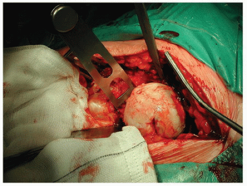 FIGURE 14-3 The neck cut is performed. A cobra retractor is placed to protect the soft tissues. |
Femoral Exposure
The leg is internally rotated and the hip flexed to visualize the proximal femur. In routine cases, neither the anterior capsule nor the iliopsoas tendon requires release. Additionally, the piriformis muscle can often be preserved. A femoral elevator is placed on the anteromedial aspect of the neck to deliver the femur into the wound (Fig. 14-4). A gluteal retractor is then passed around the greater trochanter to retract the gluteus medius and minimus (Fig. 14-5). Exposure should be sufficient to allow access down the midline of the femoral canal.
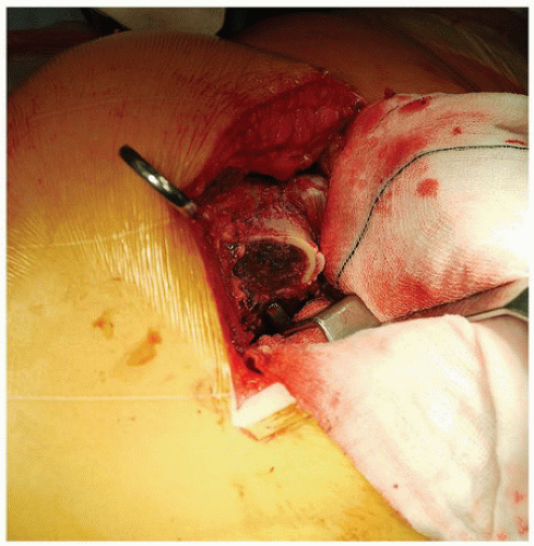 FIGURE 14-4 The femoral elevator is placed around the anterior neck to elevate the femur out of the wound. |
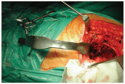 FIGURE 14-5 The gluteal retractor is placed to expose the piriformis fossa. |
Canal Preparation
The critical step is to ensure that the correct entry point in the proximal end of the medullary canal is utilized. For a straight stem, this is made posterolaterally into the piriformis fossa to allow the insertion of taper-pin reamers and rasps in the midline axis of the medullary canal. A slot in the trabecular bone of the proximal femur is made using a box chisel or specific gouges and osteotomes (Fig. 14-6). A lateral cortical ridge usually remains, which could prevent stem insertion at the correct entry point (Fig. 14-7), and this is removed using a combination of gouges and rongeurs or a high-speed burr (Fig. 14-8). The medullary canal and “true calcar” are then expanded using taper-pin reamers (Fig. 14-9). The canal is washed and aspirated, and the plug sounds are used to check the size of the canal at a level immediately distal the stem tip (Fig. 14-10). A distal PMMA plug of the measured diameter can be opened ready for implantation. Throughout preparation of the canal, care is taken to irrigate after every instrument passage to reduce the intramedullary fat load, which could otherwise embolize to the pulmonary bed. We believe this is why in a review of 9,082 consecutive patients over a 10-year period only one intraoperative death was found to have occurred, dispelling the widely accepted “myth” that cement embolization and cardiovascular collapse are common phenomena (20).
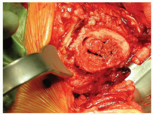 FIGURE 14-6
Get Clinical Tree app for offline access
Related posts:Stay updated, free articles. Join our Telegram channel
Full access? Get Clinical Tree


|
