Arthroscopy for Structural Hip Problems


Arthroscopy for Structural Hip Problems


Andrew J. Blackman

Aaron J. Krych

Bruce A. Levy


INTRODUCTION

The development and advancement of hip arthroscopy has facilitated the treatment of various conditions of the hip joint and surrounding structures through a minimally invasive approach. This chapter discusses the use of hip arthroscopy in structural problems of the hip and highlights indications, surgical techniques, postoperative rehabilitation, complications, and outcomes (Table 7-1).


CONTRAINDICATIONS (TABLE 7-2)

Hip arthroscopy in patients with acetabular dysplasia should be utilized with extreme caution. Numerous reports of iatrogenic instability and rapid progression of osteoarthritis after hip arthroscopy in this circumstance exist (15,16,17). However, arthroscopy can be a valuable tool in treatment of patients with labral pathology and femoral-sided deformities, even in the setting of mild acetabular dysplasia. Hip arthroscopy has also been utilized successfully to treat intra-articular pathology in patients undergoing concurrent PAO for more severe dysplasia (18).

FAI due to true acetabular retroversion may be a contraindication to arthroscopic treatment, as resection of the impinging anterolateral (AL) rim may lead to global acetabular deficiency because these patients are typically undercovered posteriorly. As in hip dysplasia, arthroscopy can be used to treat labral pathology and femoral-sided deformities in these patients. However, patients with isolated acetabular retroversion or severely retroverted sockets are usually better managed with an anteversion, or reverse, PAO (19,20). Arthroscopy may be used as an adjunct in these cases to address labral pathology.

Arthroscopic management of FAI in the setting of severe femoral or acetabular deformities may also be contraindicated. Limitations in arthroscopic techniques render treatment of posterior and medial deformities difficult or impossible. As a result, global deformities are typically best managed with open techniques, including surgical hip dislocation (19,21).

The presence of advanced degenerative changes is another contraindication to hip arthroscopy. Patients with predominantly arthritic-type pain (i.e., aching pain at rest), greater than 50% joint space narrowing, and bipolar grade 4 chondral lesions have been found to have poor outcomes after arthroscopy (7).


TABLE 7-2 Relative Contraindications to Isolated Arthroscopic Treatment of Structural Hip Problems


Acetabular dysplasia, moderate to severe


Isolated or severe acetabular retroversion


Global acetabular overcoverage (e.g., protrusio acetabuli)


Global femoral deformity (e.g., Perthes disease)


Advanced degenerative changes


PREOPERATIVE PREPARATION


Patient Assessment

Careful history and physical examination are crucial in identifying appropriate hip arthroscopy candidates. Patients must have pain referable to the hip. Often, hip pain will be localized to the groin with a classic “C” sign, but may localize to the buttock, lateral hip, lower back, thigh, and even medial knee (22). Patients with intermittent pain during activities, especially sitting and other high hip flexion activities, are optimal candidates compared to those with constant aching pain (7). Limitation of hip internal rotation in flexion as well as exacerbation of pain with flexion, adduction, and internal rotation of the hip suggest anterior FAI that may be amenable to arthroscopic treatment. In select cases, we use image-guided intra-articular local anesthetic injections as a diagnostic tool to confirm pain localization to the hip joint itself prior to proceeding with surgery (23).


Radiographic Assessment

Routine radiographs include an AP pelvis as well as frog-leg and cross-table lateral views of the affected hip. These views allow thorough assessment of the anterior and lateral femoral head-neck junction to assess sphericity and the acetabulum to assess coverage, depth, and version. The AP pelvis radiograph must be carefully scrutinized to ensure proper pelvic rotation and tilt (4) as these parameters can significantly affect radiographic markers of acetabular coverage (24). If acetabular dysplasia (lateral center edge angle [LCEA] ≤ 25 degrees) is present on the AP pelvis radiograph, a false profile view is obtained to measure the anterior center edge angle and more precisely define the degree of dysplasia (4).

Magnetic resonance imaging (MRI) and computed tomography (CT) with three-dimensional (3D) reconstructions are routinely obtained on all patients with FAI who are being considered for surgery. MRI allows for precise evaluation of the soft tissues, including the acetabular labrum and the articular cartilage, while 3D CT images provide more precise localization of areas of femoral head asphericity and acetabular overcoverage. We have found the routine use of MR arthrogram to be unnecessary in practices where high-resolution 3-tesla scanners are available.


Preoperative Planning

Once a patient has been indicated for surgery, the planned resection is templated on the plain radiographs. For the acetabular resection, a 25-degree angle is positioned on the AP pelvis radiograph to replicate a 25-degrees LCEA (Fig. 7-5A). This identifies the limit of the acetabular resection, as resection medial to this point will result in acetabular undercoverage. Areas of femoral asphericity are identified
on the AP and lateral radiographs, and planned resections, which will restore normal femoral headneck offset, are traced (Fig. 7-5B). Templating of the planned resections preoperatively allows for easy comparison to intraoperative fluoroscopy images to ensure adequate decompression is performed (25).


FIGURE 7-5 Preoperative radiographic templating of bony resection. A: A LCEA of 25 degrees is drawn on the AP radiograph. Any bone projecting lateral to this angle is safe to resect, as necessary, without causing iatrogenic dysplasia. B: The amount of bone necessary to restore femoral head sphericity and head-neck offset is drawn (dashed line) on the lateral radiograph.


TECHNIQUE


Anesthesia

Hip arthroscopy is performed under general anesthesia with muscle relaxation to facilitate hip joint distraction. We have had good success with preoperative fascia iliaca blockade to minimize intraoperative and postoperative opioid consumption (26). Controlled hypotensive anesthesia is utilized as well, with target systolic blood pressure ≤ 90 mm Hg, to minimize bleeding and facilitate visualization during the procedure.


Patient Positioning

Supine (27) and lateral (28) positioning for hip arthroscopy have been described. We routinely utilize supine positioning, as this is typically more familiar to operating room personnel and can be accomplished using a standard fracture table. Once general anesthesia has been administered, a well-padded radiolucent perineal post is inserted into the traction table and the patient is moved towards the foot of the bed until the post is in contact with the perineum. The post should be lateralized towards the operative hip so that it primarily contacts that medial upper thigh. This provides a fulcrum against which to distract the hip and theoretically reduces direct pressure on the pudendal nerve, possibly avoiding pudendal nerve injury (29,30,
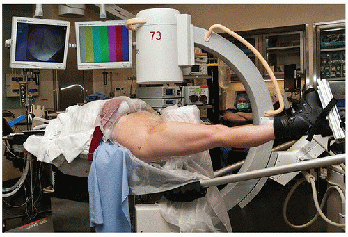
31). The contralateral arm can be left on an arm board to the patient’s side while the ipsilateral arm is draped over the chest and secured. Next, the patient’s feet are secured in traction boots in a well-padded fashion using cast padding and Coban self-adhesive wrap. The operative foot must be particularly secure to prevent slippage during the application of traction. Once the feet are secured, the foot of the table can be removed. The non-operative leg is placed in approximately 45 degrees of abduction, while the operative leg is kept in neutral rotation, slight abduction, and full extension (Fig. 7-6).


FIGURE 7-6 Photograph of final patient positioning viewed from the side of the operative extremity. Note the position of the C-arm between the legs, and the position of the overhead monitors with arthroscopic and fluoroscopic images displayed opposite the surgeon. (From Spencer-Gardner L, Krych AJ, Levy BA, (section eds). Hip Arthroscopy in Monograph Series 52: Femoroacetabular Impingement. Rosemont, IL: American Academy of Orthopedic Surgeons, E-book, 2013.)


Fluoroscopy Positioning

Ensuring that adequate fluoroscopic images can be obtained prior to prepping and draping is crucial to the success of any hip arthroscopy, in order to carry out the preoperative plan. Slight traction is applied to both legs to stabilize the pelvis. The C-arm is brought in between the legs and the beam is centered over the operative hip. The preoperative AP pelvis radiograph is displayed on a separate operating room monitor while AP fluoroscopic images are obtained. The C-arm is then adjusted until the AP fluoroscopic image closely replicates the AP pelvis radiograph. The lateral acetabulum and medial teardrop are good landmarks to use to confirm similarity between images, and the lateral acetabulum will help
identify the amount of crossover and overcoverage that should be resected. This step eliminates any discrepancies in radiographic acetabular coverage markers between the preoperative radiographs and the fluoroscopy images. Next, the C-arm gantry is rotated to a near horizontal and then horizontal position, and the ability to obtain an adequate oblique lateral and cross-table lateral, respectively, is confirmed. Note that the greater trochanter may obscure the distal femoral neck on oblique and lateral images, which, if not remedied, may cause a failure to recognize and treat distal impinging Cam lesions.


Application of Traction

At least 8 to 10 mm of hip joint distraction must be obtained in order to introduce arthroscopic instruments into the hip joint without causing iatrogenic chondral and/or labral damage (32). This typically requires 25 to 50 pounds of traction (27). In-line traction is applied to the operative leg, and countertraction is applied to the nonoperative leg. Initial traction is applied with the operative hip slightly abducted, and subsequent adduction will assist with joint distraction, due to the fulcrum of the perineal post.


Portal Placement (Table 7-3)

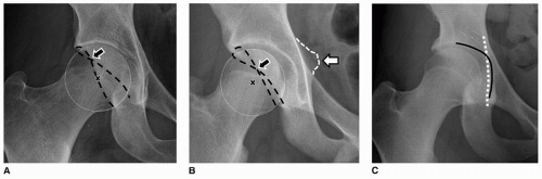
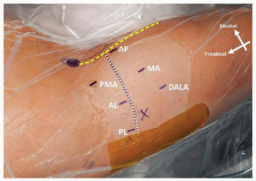
Anatomic landmarks for portal placement are identified only after joint distraction is established to prevent migration of the skin relative to the underlying bony landmarks. The first landmarks to identify and mark are the anterior superior iliac spine (ASIS) and the tip of the greater trochanter. Two perpendicular lines are then drawn: one from the ASIS distally to the center of the patella and one from the tip of the trochanter anteriorly to the intersection with the first line (Fig. 7-7). Subsequent portal placement should be kept lateral to the ASIS-to-patella line to minimize risk of femoral nerve injury (33,34).


TABLE 7-3 Starting Points for Specific Hip Arthroscopy Portals (33) (Fig. 7-7)


Anterolateral portal—established in line with the anterior border of the greater trochanter 1 cm proximal to the horizontal line; a soft spot can often be felt here just anterior to the tensor fascia lata insertion onto the iliotibial band.


Posterolateral portal—established in line with the posterior border of the greater trochanter 1 cm proximal to the horizontal line.


Anterior portal—established just distal and lateral to the intersection of the vertical and horizontal lines.


Mid portal—roughly localized by creating a distally directed equilateral triangle with the anterior portal and AL portal; exact location varies with patient body habitus and orientation as well as amount of acetabular version.


Proximal mid portal—roughly localized by creating a proximally directed equilateral triangle with the anterior portal and AL portal; exact location varies with patient body habitus and orientation.


Distal anterolateral accessory portal—established in line with the AL portal, 4-5 cm distal to it.


FIGURE 7-7 Intraoperative photograph of potential portal placement sites. To aid portal starting point identification, two perpendicular lines are drawn: one from the ASIS distal to the center of the patella (yellow dashed line) and one from the tip of the greater trochanter anteriorly to the intersection with the first line (white dotted line). X, middle of greater trochanter; darkened circle, anterior superior iliac spine; AP, anterior portal; MA, midanterior portal; DALA, distal anterolateral accessory portal; PMA, proximal midanterior portal; AL, anterolateral portal; PL, posterolateral portal. (From Spencer-Gardner L, Krych AJ, Levy BA (section eds). Hip Arthroscopy in Monograph Series 52: Femoroacetabular Impingement. Rosemont, IL: American Academy of Orthopedic Surgeons, E-book, 2013.)


The vast majority of hip arthroscopy for FAI in our practice is performed using two portals— midanterior (MA) and AL. A spinal needle through the posterolateral (PL) portal is used for outflow purposes. Under fluoroscopic guidance, a 6-inch spinal needle is advanced from the AL portal starting point towards the hip joint at an insertion angle of approximately 15 degrees towards the floor and 15 degrees cephalad. As the spinal needle is advanced into the joint, care must be taken to avoid piercing the labrum and avoid damaging the femoral articular cartilage. To aid in this, the needle is aimed just proximal to the femoral head (as far from the labrum as possible) with the bevel towards the head (to minimize risk of iatrogenic cartilage injury) (35).

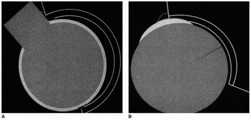
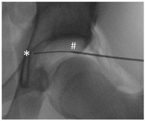
Once the spinal needle is in the hip joint, the stylet is removed and air is injected into the joint to create an air arthrogram. A second AP fluoroscopic image is obtained. If the spinal needle has migrated proximally, it may be within the labrum and should be removed and positioned more distally. If the spinal needle remains stationary after the air arthrogram, it is safe to proceed with instrumentation of the hip joint. A Nitinol wire is threaded through the spinal needle until resistance is met. Position is checked on fluoroscopy, and the guide wire should be seen abutting the medial acetabular wall (Fig. 7-8). If the guide wire does not advance all the way to the medial wall, it may be too anterior or posterior and the spinal needle should be repositioned accordingly. If needed, a lateral fluoroscopic image can help determine anteroposterior placement of the spinal needle.

After confirming proper intra-articular position, a skin incision is made over the guide wire. A 4-mm dilator is passed over the guide wire followed by the 4.5-mm arthroscopy trocar. This step should be performed with a twisting motion and slow, controlled pressure to minimize the risk of plunging and damaging the articular cartilage after the hip joint capsule is pierced. The 70-degree arthroscope is introduced into the hip joint dry with the inflow turned off.

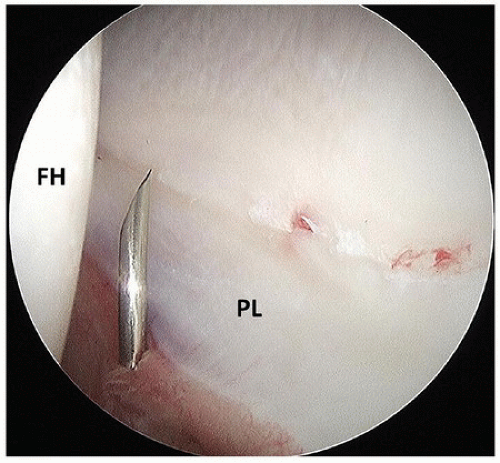
Under direct visualization, the PL outflow portal is now established. Looking posteriorly, the “V” between the posterior labrum and the femoral head is identified (Fig. 7-9). The 6-inch spinal needle is advanced from the PL portal starting point to the center of this “V.” The typical trajectory is 5 degrees towards the ceiling and 5 degrees cephalad, with slight convergence to the camera in the AL portal.

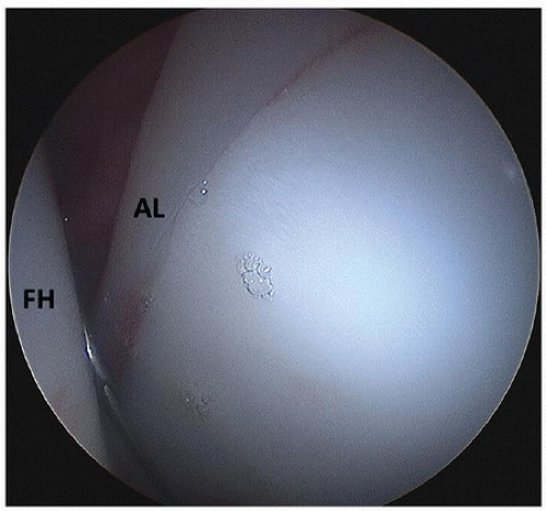
Next, the MA portal is established under direct visualization. Looking anteriorly, the “V” between the anterior labrum and the femoral head is identified (Fig. 7-10). The 6-inch spinal needle is advanced from the MA portal starting point to the apex of this “V,” with a typical trajectory of 25 degrees towards the floor and 35 degrees cephalad. Once the spinal needle is properly positioned, the stylet is removed and a Nitinol guide wire is inserted. A skin incision is made, and the 4-mm dilator is threaded over the wire, followed by a 6-mm dilator.


FIGURE 7-8 Intraoperative fluoroscopic image showing a Nitinol wire passed through the spinal needle in the AL portal abuts the medial acetabular wall (*), indicating proper portal placement. Note the positioning of the spinal needle, near the femoral head with the bevel directed towards the head (#).


FIGURE 7-9 Arthroscopic image looking posteriorly from the AL portal visualizing the “V” between the femoral head (FH) and the posterior labrum (PL). The spinal needle has been introduced through the PL portal.


FIGURE 7-10 Arthroscopic image looking anteriorly from the AL portal visualizing the “V” between the femoral head (FH) and the anterior labrum (PL). The spinal needle has been introduced through the MA portal.


Capsulotomy

A curved arthroscopic knife is inserted through the 6-mm dilator in the MA portal, and the dilator is removed from the joint. At this point, the inflow is turned on and the presence of outflow is confirmed. The capsulotomy is extended anteriorly from the MA portal first. Then, an arthroscopic cannula is placed in the MA portal, and two switching sticks are used to switch the camera to the MA portal and the arthroscopic knife to the AL portal. The capsulotomy is then extended posteriorly from the AL portal to the PL outflow needle. Portals are once again switched, and an interportal capsulotomy is made by extending the anterior capsulotomy posteriorly from the MA portal to the

Only gold members can continue reading. Log In or Register to continue

Stay updated, free articles. Join our Telegram channel

Jun 14, 2016 | Posted by in ORTHOPEDIC | Comments Off on Arthroscopy for Structural Hip Problems

Full access? Get Clinical Tree

Get Clinical Tree app for offline access