Fig. 40.2
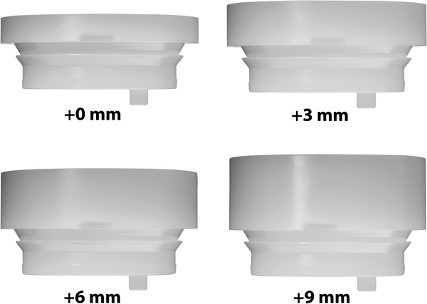
Small, standard, and large body sizes are available. Up-sizing reverse body height provides a means of adding additional humeral length if needed when tensioning the soft tissues

Fig. 40.3
Four polyethylene liner thicknesses are available in the standard or retentive depths
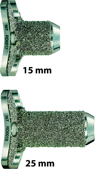
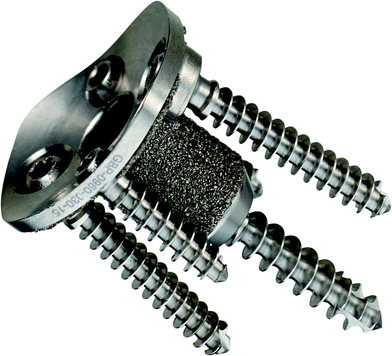
The platform of the glenoid is a concave, pegged baseplate with porous coating on the peg and backside of the implant. There is a 15 mm standard peg length and a 25 mm peg length for use in revision situations and when bone graft is required (Fig. 40.4). A non-locking 5.5-mm central screw provides compression of the baseplate against the prepared glenoid face. Variable angle 4.5-mm screws can be placed in superior, inferior, anterior, and posterior positions. The superior and inferior screws are locked following screw placement to create a fixed-angle construct. The anterior and posterior screws are placed in a non-locking fashion (Fig. 40.5).


Fig. 40.4
The glenoid baseplate includes a 15- or 25-mm central peg

Fig. 40.5
Screw fixation of the baseplate occurs through a central compression screw and four possible peripheral screws. The superior and inferior screws are locked after placement for a fixed-angle construct
The glenosphere is a 38-mm-diameter cobalt chrome implant with 5 options with respect to lateral offset and inferior offset. Glenosphere options include a concentric implant with 2 and 5 mm of lateral offset, a 4-mm eccentric implant with 2 and 5 mm of lateral offset and 4-mm eccentric inferior lipped implant with 2-mm lateral offset (Fig. 40.6).


Fig. 40.6
Multiple glenosphere options allow variable combinations of lateral offset and eccentric placement to minimize scapular notching
Flexibility of the Implant System
The goal of reverse total shoulder arthroplasty is to provide pain relief and functional improvement while avoiding complications such as dislocation and scapular notching. Several implant-related factors contribute to stability and function following reverse shoulder replacement and may play a role in contributing to or avoiding these complications. The prosthetic factors that can be altered include varying offset of the glenosphere, varying humeral length through a combination of body height and polyethylene insert thickness, as well as inferior placement or eccentricity of the glenosphere. In order to prevent scapular notching, it has been suggested that the glenosphere be placed inferior on the glenoid face by positioning the baseplate inferiorly or using an eccentric taper on the glenosphere with or without inferior tilt of the glenosphere. Another method of minimizing the risk of scapular notching is by increasing the lateral offset that moves the center of rotation away from the face of the native glenoid. Any alteration of inferior positioning of the glenosphere +/- inferior tilt or lateralizing the center of rotation can influence shoulder function. In a computer-simulated model, Gutierrez established a hierarchy of surgical- and implant-related factors for impingement-free abduction and adduction following RSA [10]. The hierarchy of factors associated with increased impingement-free abduction was lateral offset, inferior placement of the glenosphere, inferior tilt of the glenosphere, humeral neck-shaft angle, and prosthetic size. With respect to impingement-free adduction, the hierarchy of factors was neck-shaft angle, inferior placement of the glenosphere, lateral offset, and glenosphere size.
The Integra® Titan™ Reverse Shoulder System provides variability of humeral length, glenosphere lateral offset, and eccentricity of the glenosphere. The ability to manipulate each of these implant factors individually or in combination allows the surgeon to tailor the implant characteristics to the patient’s pathology.
The neck-shaft angle of the humeral component is fixed at 142°. This permits easier access to the glenoid vault and angles the inferior aspect of the polyethylene insert away from the scapular neck and lateral pillar of the scapula, thereby reducing the risk of scapular notching.
Surgical Flexibility
The utility of any implant system lies in its ease of insertion and the ability to manage multiple clinical situations, particularly in revision surgery. The Integra® Titan™ Reverse Shoulder System is designed with each of these concerns in mind.
The humeral implant provides multiple options of body height and polyethylene thickness to provide appropriate soft tissue tension. In order to allow for the maximum options for humeral length, it is recommended that the stem be sized for a small reverse body. This allows humeral length to be increased by upsizing the body length to a standard (+5 mm) or a large (+10 mm) body beyond the additional 9 mm of polyethylene. Beginning with a small body, 19 mm of additional humeral length is accomplished through the body (up to 10 mm) and the polyethylene insert (up to 9 mm).
The foundation of the glenoid is the baseplate. The implant design allows the baseplate to be placed at or near the center of the glenoid vault with enough flexibility of the glenosphere to provide offset and eccentric placement of the glenosphere relative to the baseplate. Lateral offset serves two main functions. By moving the center of rotation away from the lateral pillar of the scapula, it reduces the likelihood of scapular notching. Additionally, it allows better tensioning of the remaining rotator cuff that can improve the postoperative function, particularly external rotation. The role of eccentric placement of the glenosphere relative to the baseplate is dependent on the location of the baseplate. If the placement of the baseplate in the glenoid results in abutment of the inferior aspect of the humeral polyethylene liner on the scapula when using a concentric glenosphere, a 4-mm eccentric glenosphere places the inferior aspect of the sphere below the lateral pillar of the scapula and glenoid neck. This reduces the chance of scapular notching. If the baseplate is placed inferior enough such that proper inferior clearance is obtained with a concentric glenosphere, a 4-mm eccentric sphere provides humeral length when tensioning the soft tissues. This combination of lateral offset and a 4-mm eccentric taper allows multiple options to reduce the likelihood of scapular notching and achieving appropriate tension of the soft tissues.
Surgical Technique
Step 1
Preoperative Templating and Patient Positioning
Preoperative evaluation of the humerus using the reverse shoulder system X-ray templates helps determine the size of the prosthesis and level of the humeral head resection. The goal is to remove the humeral head at the neck-shaft inclination angle of 142°, and humeral version from neutral to 20° of retroversion. Place the patient in beach chair position.
Step 2
Exposure
A deltopectoral approach is used to provide exposure to the anterior aspect of the glenohumeral joint, the upper humeral shaft, and the humeral head.
Step 3
Lesser tuberosity osteotomy and subscapularis tenotomy
Step 4
Capsule Release and Humeral Head Dislocation
Step 5
Humeral Head Preparation and Resection
Assess the humeral head and remove any unwanted osteophytes to return the proximal humerus to near native anatomy.
Freehand Head Resection Technique
Place the 142° head cutting template along the anterior aspect of the arm parallel to the shaft of the humerus and mark the angle at which the humeral head will be resected with an oscillating power saw or mallet and large osteotome. There are two proximal holes on the head cutting template for 3.2-mm fixation pin placement, if preferred. A zero degree threaded version hole for the template handle is also available to assess retroversion.
The saw or osteotome should enter the anterior surface of the humerus above the anatomic neck and exit 2–3 mm proximal to the posterior cuff attachment. Once completed, the resection will remove less humeral head than the primary total shoulder resection of 135°.
Head Resection with an Intramedullary Cutting Guide
Attach the T-Handle to the Starter awl and create a pilot hole at the top of the humerus, in line with the long axis of the humerus just lateral to the articular surface of the head of the humerus and medial to the attachment of the rotator cuff.
Leave the Starter awl in place and clamp the IM Head Cutting Guide, 142°, around the awl shank by tightening knob 1. The Version Rod is then passed through the holes in the resection guide and is rotated into the desired retroversion. The holes denote 20°, 30°, and 40° of retroversion, in reference to the forearm axis. A zero degree version hole is provided on the IM Head Cutting Guide, 142°. If more or less retroversion is required, use the orientation holes on the resection guide collar and rotate the forearm to desired angle accordingly. Slide the Reverse IM Head Cutting Guide, 142°, against the humerus and tighten knob 2. Adjust the resection level by sliding the IM Head Cutting Guide, 142°, up or down and tightening knob 3.
The Head Cutting Depth Gauge can be used to assess the cutting plane. Before the oscillating saw blade (33 × 0.8 mm) is placed along the flat surface of the IM Head Cutting Guide, 142°, drill two 3.2-mm fixation pins through the Reverse IM Cut Block and into the underlying bone which will stabilize the guide. Remove the Head Resection Guide-Starter awl assembly by loosening knob 3 on the IM Head Cutting Guide, 142°, and removing the Starter awl out of the humerus. Use an oscillating saw through the capture to remove the humeral head. If additional head resection is needed, lower the blade to the next slot. This will remove 3 mm of additional bone. After removing the humeral head, extract, the fixation pins using the pin puller.
Stay updated, free articles. Join our Telegram channel

Full access? Get Clinical Tree


