Chapter 105 Surgical Techniques and Instrumentation in Total Knee Arthroplasty
Relevant Knee Anatomy and Alignment
Creating a plan for successful biomechanical reconstruction of the knee requires specific knowledge of an individual patient’s anatomy that includes an understanding of alignment, ligamentous support, and skeletal anatomy at the knee, hip, and ankle. Thus, it is important to examine a patient in three positions: weightless, standing, and when walking. The weightless examination, with the patient seated or supine, allows careful assessment of ligament competence, range of motion, and passive patellar tracking. When the patient is standing, one can assess the overall axial alignment of the leg, the angle of the joint line in dual stance, and the static position of the patella. Walking the patient allows one to add a dynamic component to the examination, while observing the presence of antalgic movement, soft tissue impingement, and varus or valgus thrust during active single leg stance. Considerable variation is noted in body habitus, natural femoral anteversion, foot and ankle alignment, and patterns of gait, requiring caution in describing what is “normal.” However, the following description represents consensus.98,134
Static Alignment
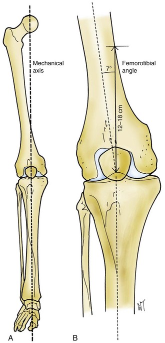
The mechanical axis of the leg (Fig. 105-1) is formed by a line that passes from the center of the hip through the center of the knee into the center of the ankle joint. The offset is the distance between the femoral shaft and the center of rotation of the hip, which is determined by the angle of the femoral neck and length of the neck and shaft of the femur. A valgus angle of 5 to 9 degrees between the femoral and tibial shafts allows the transverse axis of the knee joint to be perpendicular to the midline vertical axis of the body. Because the proximal-to-distal mechanical axis forms an angle of 3 degrees with the midline vertical axis of the body, there typically exists a 3-degree angle between the knee joint line and the axis of the tibial shaft, and a 10-degree angle between the joint line axis and the axis of the femoral shaft. Hungerford and Krackow94 and Townley204 have pointed out that the “normal” angle of proximal tibial varus is variable because of inherited and developmental anatomic factors such as pelvic width, femoral neck varus, femoral and tibial bowing, physeal growth, and femoral length. Because of the fact that the mechanical axis passes through the medial compartment, and the transverse knee joint axis is in slight varus, the distribution of body weight when standing is more medial than lateral in most knees.92,97,144,204
Dynamic Alignment
During normal walking, the center of gravity of the body moves toward the supporting leg during each gait cycle. The leg typically will move toward the midline during single leg stance. However, the distribution of contact forces across the knee joint is not symmetrical; it is estimated that between 60% and 75% of these forces are carried by the medial compartment of the knee for reasons discussed in the previous section.85,103,144
Johnson and associates103 noted that during normal walking, a greater medial load than predicted is observed because of the laterally directed ground reaction force. These forces do not rest on a perpendicular tibial plateau; the anatomic tibial plateau is sloped 2 to 10 degrees posterior and distally. However, when the menisci are taken into account, the cartilaginous articulation is not posteriorly sloped; only the bony surfaces give the appearance of posterior slope. Furthermore, the medial tibial subchondral bone is concave (“dished”) relative to the more convex lateral tibial subchondral surface. Combined with the 3-degree angle of the tibial anatomic axis relative to the transverse knee axis, a varus moment is imparted during normal gait. This varus moment creates a lateral “thrust,” which is resisted by the lateral stabilizing force arising from the capsule, the lateral collateral ligament (LCL), the cruciate ligaments, the ligamentum patellae, the popliteus, the posterior oblique ligament, and the iliotibial band (ITB).134
Abnormal patterns of gait can impact the loading of the knee joint. Muscle imbalance due to deconditioning or obesity can accentuate a varus thrust or cause the thighs to rub together during the swing phase of gait. Gait studies performed on obese patients have demonstrated locomotor adaptations, such as slower speed, shorter steps, increased double support time, and decreased knee range of motion. Additionally, Sharma and colleagues189 reported on a correlation between body mass index (BMI) and osteoarthritis (OA) severity in knees with varus malalignment that was not seen in knees with valgus malalignment. Compensatory external rotation of the foot is a mechanism of unloading a painful medial compartment during stance. An extension moment moving the center of gravity anterior to the knee joint is a compensatory mechanism for quadriceps weakness that eventually can lead to laxity in the posterior capsule and the posterior cruciate ligament.
Objectives of Prosthetic Replacement
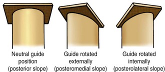
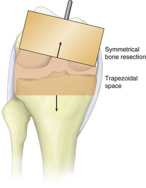
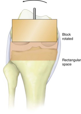
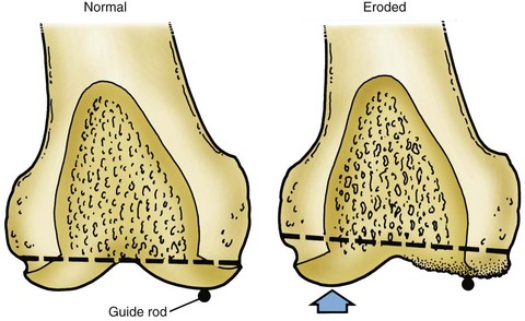
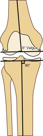
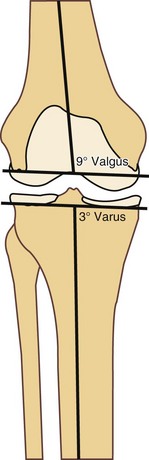
Practical considerations have an impact on proper implant alignment. Given the human error factor, reproducibility during surgery is important. Instrumentation and careful operative technique can minimize the incidence of component malposition. Computer navigation of knee surgery has been shown to improve the accuracy of component positioning by reducing the incidence of alignment outliers,32,41 but later studies demonstrated that this effect may be tied to the setting in which navigation is utilized. Carter and coworkers26 demonstrated reduction in “outliers” with respect to number and severity when navigation was utilized in a low-volume, community-based practice, but recent studies from high-volume centers have found no statistical difference in component positioning or reduction in outliers through the use of navigation.84,110 For most surgeons, it is easier to make a right-angle bone cut than an oblique one, and it is easier (and thus more reproducible) to make a cut across the upper tibia at right angles to the tibial shaft than to make a cut that is inclined 3 degrees medially and 10 degrees posteriorly (Fig. 105-2). Additionally, if angle cuts are not appropriately adjusted from a rotational perspective, further inaccuracy results; for example, an intended 10-degree posterior slope may result in a combination of posterior and valgus slope if the cutting guide is internally rotated (Fig. 105-3). Also, because referencing off of pathologic bone surfaces is likely to result in errors in both angular and rotational alignment due to loss of bone and absence of the soft tissue contribution to alignment, one might choose not to reproduce the original joint surfaces. In pathologic states, which in themselves create secondary changes in the ligaments, this difficulty is obviously compounded.
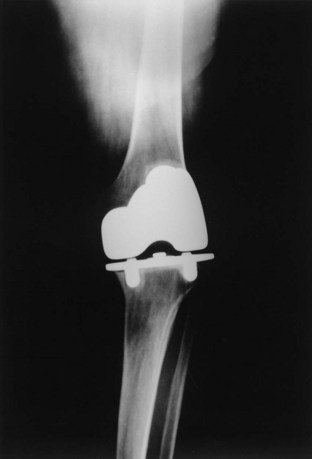
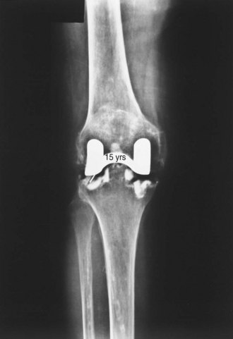
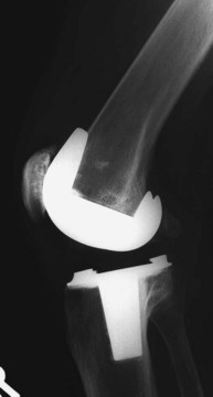
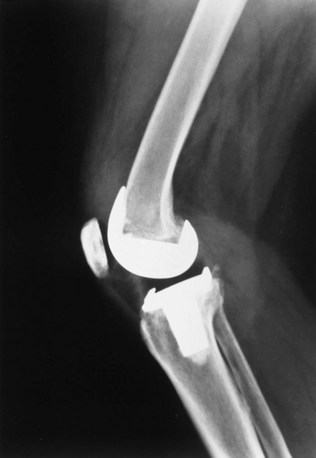
Insall believed that restoration of “normal” anatomy often was not achieved, and perhaps was not important to success. Evidence to support this assertion is that early models of knee prostheses were crude, often grossly mismatched in size because of a limited inventory of sizes, incompatible with ligamentous structures, and often inexpertly inserted. Many of these devices failed, but a surprising number not only worked well but continued to do so for many years, proving the human body’s remarkable resilience (Fig. 105-4). As clinical experience increased, surgical expertise improved, and prosthetic design became more sophisticated, more durable, and more “natural” through designs that did not set up kinematic conflict with soft tissue structures. Today, in addition to painlessness, normality of feel, less invasive approaches, and a high level of function are often achieved. Nevertheless, total knee replacement is not universally successful, with some patients continuing to experience anterior knee pain, crepitation, or effusion despite dramatic functional improvement relative to the original pathologic state. Furthermore, some individuals, such as Middle Eastern and Asian patients who need significant knee flexion during prayer, require special design considerations.
Polyethylene wear continues to be a major clinical issue. Designers of knee implants have two possible routes to minimize wear potential: decreasing contact stresses or changing the mechanical properties of the bearing surface. Ideal “anatomic” highly conforming joint surfaces may conflict with the bioengineering requirements needed to reduce wear. In addition, modularity has introduced the potential for wear secondary to micromotion between the polyethylene insert and the tibial tray.72,156,209,211 Recent studies have suggested that patterns of “backside wear” indicate differing mechanisms of wear at the two interfaces with a predominance of burnishing, dimpling, and deformation at the insert/tibial tray interface,84,126 and other authors have investigated the wear patterns of the tibial post in posterior stabilized designs, noting that variations in wear are dependent on component design and degree of femoral flexion.48 Despite the potential for increased wear debris generated by unintended backside movement, investigators have demonstrated that modular components can demonstrate comparable survivorship when compared with monoblock systems.88 At least partial conformity between the articulating components in fixed-bearing designs is considered necessary to reduce high polyethylene stresses and to provide acceptable durability. Thus, all current fixed-bearing designs are compromises between conformity and mobility. Increasing conformity at the bearing surface can be combined with intended motion between the undersurface of the polyethylene and the tibial tray to reduce contact stress without adding constraint. This combination of conformity and motion is the theory that drives the mobile-bearing total knee concept. Polyethylene manufacturing techniques also play a role in determining the balance of conformity and durability. The cross-linking of polyethylene has proven safe and beneficial for decreasing wear rates.89 When cross-linking is carried out in an oxygen-free environment (to reduce free radical formation), cross-linked polyethylene demonstrates lower rates of delamination or fracture.40 Further advances in processing of polyethylene include combinations of cross-linking and annealing or heating the polyethylene past the melt point to retain even more of its original resistance to cracking and to address the issues of longevity associated with free radical formation.208 The optimal balance between improvement in wear properties and reduction in mechanical properties such as elongation to fracture created by the cross-linking process still remains to be defined.
Theories of Surgical Technique
The development of implants and instruments led to two distinct surgical techniques during the early development of knee arthroplasty: the gap balancing technique and the measured resection technique.51 Over time, instrument systems have adopted aspects of both philosophies, blurring the distinctions. The gap balancing technique was developed in conjunction with the design of cruciate substituting prostheses. The measured resection technique was developed by surgeons and designers who favor cruciate retention, emphasizing measured femoral and tibial resection as the primary consideration.
Gap Balancing Technique
The gap balancing technique71,96,98 is used in conjunction with cruciate substituting prostheses and some cruciate retaining devices (often accompanied by posterior cruciate release from the posterior tibial insertion). Ligament releases (see later) are performed to correct fixed deformity, bringing the limb into approximate alignment before bone cuts are made (Fig. 105-5).
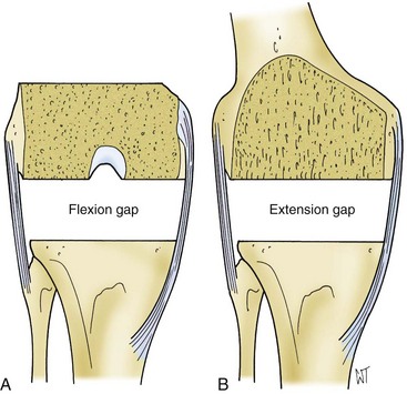
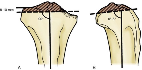
A particular sequence of steps in balancing the flexion gap was not deemed essential for the gap technique. The femur or tibia may be osteotomized first; the goal is to create a balanced flexion gap (Fig. 105-6). Insall traditionally would perform the tibial cut first, measure the flexion gap, and then make the distal femoral cut at a point such that the extension gap would match the flexion gap. The proximal tibial osteotomy is performed 10 mm below the least compromised articular cartilage (Fig. 105-7). A perpendicular tibial cut establishes proper limb alignment with reference to the distal femoral cut. Harada and coworkers83 suggested that the proximal tibia weakens below a depth of 5 mm, prompting many surgeons to resect as little bone as possible and requiring the use of thinner polyethylene inserts at the risk of stress-related wear.225 Clinical experience and later research on tibial bone strength76 have supported a 10-mm cut below the joint line, obviating the need to use excessively thin polyethylene components. When the posterior cruciate ligament (PCL) was resected, the flexion gap would open up a few millimeters, often necessitating a distal femoral cut that would slightly elevate the joint line to match the flexion and extension gap. Insall would then proceed to balance the flexion gap by positioning the anteroposterior cut on the distal femur parallel to the tibial cut surface, often in line with the transepicondylar axis. When the gap theory is applied to cruciate retaining designs, the PCL may be retained if it is appropriately balanced and the joint line position is restored with modular tibial inserts.
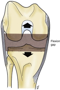
Figure 105-6 The flexion gap is created first by removing bone from the tibial plateaus and the posterior femoral condyles.
Rotational Alignment of the Femur
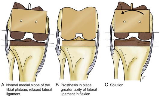
The rotational alignment of the femoral component is determined by the anatomy of the femur and is influenced to some degree by the condition of periarticular tissues. In a standard varus knee, when a medial release is not required for axial alignment, some external rotation of the femoral anteroposterior (AP) cutting block is needed to compensate for the normal medial inclination of the tibial plateau and the flexion laxity of the lateral ligamentous structures (Fig. 105-8). Only by this external rotation can a rectangular “flexion gap” be produced (Figs. 105-9 and 105-10). However, when a medial soft tissue release is done, a rectangular flexion gap is created by the ligament release itself, and the femoral template can be positioned anatomically relative to the epicondylar axis of the distal femur or the proximal tibial resection plane.
Proper femoral rotation is essential because inappropriate femoral component rotation may result in many downstream biomechanical issues such as flexion instability and patellofemoral maltracking problems.8,15,164 Although an arbitrary external rotation of 3 degrees is often satisfactory,68,163 several methods have been developed in an effort to accurately determine appropriate femoral rotation (Fig. 105-11):
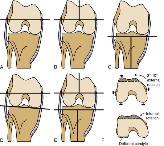
Femoral rotation is difficult to instrument precisely because of surface landmark inconsistencies and obscurities; the surgeon must form her or his own judgment upon taking many factors into account, making sure to err on the side of slight external rotation, never internal rotation.8,15,164 The posterior condylar axis (PCA) is frequently used as the reference for femoral rotation; however, posterior condylar erosion as part of the arthritic process, particularly in the valgus knee, often distorts this reference angle; and so, it probably should not be relied on as the sole method of determining femoral rotation.81,196 The AP axis of the femoral sulcus, described by Whiteside and Arima,9,218 has also been shown to be an accurate reference point for determining femoral rotation; however, it has been shown to be less reliable in cases of trochlear dysplasia and valgus deformity.159 The tibial shaft axis has been described as an effective reference axis for defining femoral rotation.196 Using the anatomic axis of the tibia is particularly useful because it should facilitate balancing the flexion space when perpendicular proximal tibial cuts are created and subsequently used as a reference for femoral component rotation.
Insall preferred the epicondylar axis as the reference that would most closely re-create the patient’s natural femoral rotation.17,159 The center of the medial epicondyle is located in a sulcus that lies between the proximal origin of the superficial deep medial collateral ligament (MCL) and the distal origin of the deep MCL. The medial epicondylar ridge at the origin of the superficial MCL can be identified by isolating the condylar vessels that lie proximal and anterior to the medial epicondylar ridge. From these vessels, the epicondylar ridge can be readily outlined; the center of this outline is the sulcus, which typically can be palpated without dissection (Fig. 105-12). The lateral epicondyle is the most prominent point on the lateral aspect of the distal femur. Following the lateral condylar vessels (similar to the medial side) confirms the exact location of the lateral epicondyle, lying immediately distal to the vessels (Fig. 105-13). The line across the distal femur connecting the epicondyles with the knee flexed to 90 degrees is the epicondylar axis.
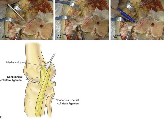
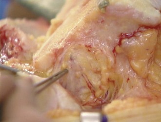
Figure 105-13 Intraoperative photo of the lateral epicondyle, the most prominent point on the distal lateral femur.
The benefit of having several different methods of assessing femoral rotation is that one or more can be used to confirm the surgeon’s preferred method (Fig. 105-14). Several investigators have compared these various methods. Poilvache and associates159 correlated the transepicondylar, anteroposterior, and posterior condylar axes. Berger and colleagues17 and Griffin and coworkers80 described the relationship of the epicondylar axis to the posterior condylar axis. Whiteside and Arima9,218 defined the relationship of the anteroposterior and posterior condylar axes. Stiehl and associates196 demonstrated that referencing from the tibial shaft axis is more accurate than referencing from the PCA. More recently, Katz and colleagues107 found that using the transepicondylar axis was less predictable and resulted in excessive external rotation as compared with the AP axis and the balanced tension line. Fehring65 reported rotational errors of at least 3 degrees occurring in 45% of patients when rotation was determined by fixed bony landmarks as compared with the balanced tension line. One study compared the use of the PCA and the transepicondylar axis (TEA) and demonstrated a decrease in the requirement for lateral retinacular release when the TEA was used: 56.9% with PCA reference versus 12.3% with TEA reference.151
As previously mentioned, the use of computer navigation has been proposed as a way to improve component position. In a study conducted to evaluate computer navigation as it relates to femoral rotation, it was reported that intraoperative decisions should be based on a combination of reference points, and that computer navigation alone suggested the incorrect femoral size in up to 50% of the cases reviewed. Furthermore, 34% of cases required intraoperative adjustments in rotation from the computer-modeled placement.14 Ultimately, the determination of whether the rotation is “correct” will be made by considering all available anatomic references, ensuring proper tracking of the patella, and confirming unconstrained movement of the tibiofemoral articulation.
Anterior versus Posterior Referencing
Flexion Gap
In contrast to the early days, when gap balancing was developed, there exists now a larger range of femoral component sizes, with combinations of width and depth of the component allowing better matching of the patient’s dimensions. Nevertheless, there will seldom be an exact match between the sagittal dimension of the femoral component and the actual size of the bone, necessitating some compromise to create a balanced knee. With anterior referencing, the size of the component is based on the amount of the posterior femoral condyle that is removed. Thus, the size of the flexion gap after the posterior condylar resection will differ from anatomic if the exact amount of resected condyle does not equal the amount replaced by the femoral implant. To create equal flexion and extension gaps, adjustments in the distal femoral resection (extension gap) may be necessary when the posterior condyles are over-resected. Over-resection of the posterior condyles can cause flexion instability, and under-resection can lead to excessive tightness in flexion, particularly when the PCL is preserved. Conversely, with posterior referencing (Fig. 105-15), the flexion gap is constant, but variability in sagittal size creates a risk of “notching” the anterior femoral cortex with an aggressive resection of bone, or of having the femoral flange sit anterior to the anterior femoral cortex when the component is larger than the bone. To compensate for in-between sizing when using anterior referencing, Insall recommended downsizing components and placing the femoral component in slight flexion (typically 3 degrees) to lessen the risk of anterior notching (Fig. 105-16). The same effect can be achieved if the instrument system creates a slightly divergent (as opposed to parallel to the anterior cortex) anterior cut, also minimizing the risk of anterior femoral notching.
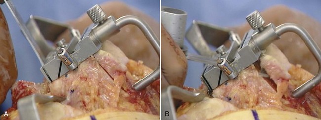
After the posterior condylar cut is made, the flexion gap between the surfaces of the posterior femoral condyles and proximal tibia is measured. Insall’s original technique included spacer blocks to determine the gap size (Fig. 105-17). An alternative to static blocks is to use ligament tensor devices, ranging from something as simple as a lamina spreader to a more complicated sensor with a digitally calibrated read-out. The tensor technique measures soft tissue tension on the medial and lateral sides of the gap (Figs. 105-18 and 105-19). Using the tensor work flow, the proximal tibial cut is made first. The tensors then allow the surgeon to properly tension the flexion space and create a corresponding posterior condylar cut (Fig. 105-20). The size of the flexion space corresponds to the combined thickness of tibial and femoral components and determines the thickness of the tibial component required to stabilize the knee in flexion. If the flexion gap is not symmetrical, then additional ligament release procedures, as described later, may be necessary to establish flexion space symmetry. Alternatively, lack of flexion space symmetry may be the result of improper femoral rotation, requiring adjustment to correct rotation and balance the flexion gap.
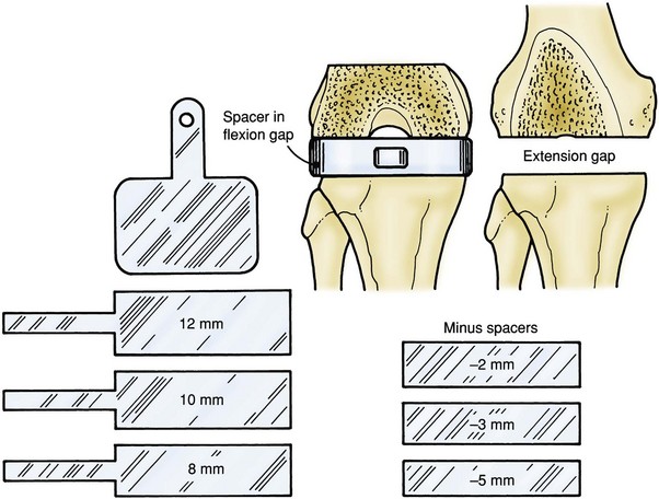
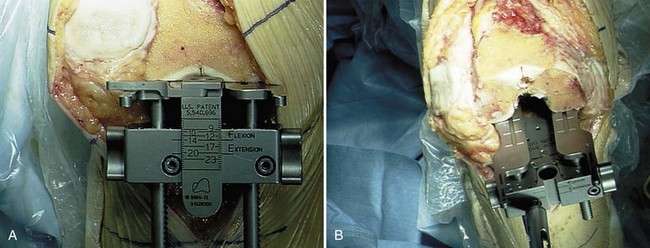
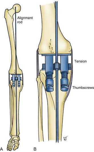
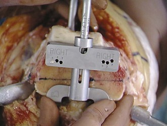
Figure 105-19 By adjusting the medial and lateral thumbscrews of the tensor, the alignment rod is brought into the mechanical axis.
Extension Gap
As with the flexion gap, sizing of the extension gap is performed using spacers or a tensioning device. For balancing gaps, the distal femoral osteotomy is performed after the proximal tibial cut is completed. The extension gap represents the combined thickness of the femoral component and the tibial component. With this concept in mind, the distal femoral resection is made to accommodate the thickness of both components, while matching the flexion gap measurement. One approach to creating the proper distal femoral resection depth is to cut the distal femur at a predetermined level (usually 10 mm above the joint line) corresponding to the thickness of the femoral component alone (Fig. 105-21). The extension space so formed is then assessed with a spacer block or tensiometer, and the distal femur is recut when necessary to match the flexion gap (see Fig. 105-18). In this way, the amount of additional resection can be calculated from the difference between the thicknesses of the flexion block and the extension block. Cutting away more distal femur than the femoral component will ultimately replace should be minimized as it will elevate the joint line. When a preoperative flexion contracture contributes to gap imbalance, appropriate soft tissue balancing and posterior release should be performed before additional bone resection is considered.
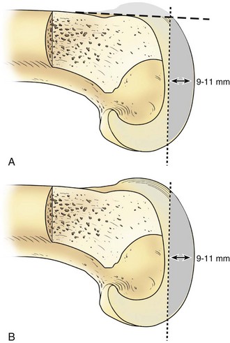
Figure 105-21 The thickness of the prosthesis, normally somewhere between 9 and 11 mm, is removed from the distal femur.
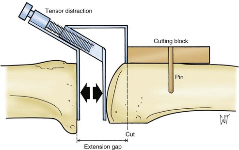
An alternative to using a predetermined distal femoral resection is to cut the extension gap in one step based on the measured height of the flexion gap. When a one-step distal cut is performed, the knee is extended and axial traction is applied on the limb with a mechanical device such as a tensor (see Figs. 105-18 to 105-20). With the soft tissue under proper tension, the level of distal femoral osteotomy is determined by the thickness of spacer blocks that fit the flexion gap. A distal femoral osteotomy is performed at this level perpendicular to the mechanical axis and at a measured valgus angle relative to the anatomic axis of the femur (Figs. 105-22 through 105-24). The valgus cut on the distal femur relative to the anatomic axis is the difference between anatomic and mechanical axes, which can be measured using long cassette radiographs. Once again, the surgeon should recognize the fact that removing more distal bone than the femoral implant replaces will result in elevation of the joint line.
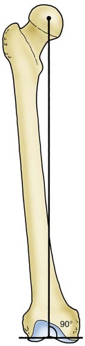
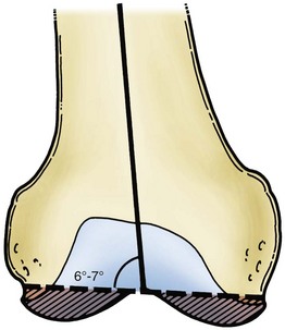
Figure 105-23 The distal femoral cut is normally aligned at 6 to 7 degrees of valgus from the intramedullary alignment rod.
Pros and Cons of the Gap Balancing Technique
Potential pitfalls of the gap technique include the following:
Classic Measured Resection Technique
The second theory of surgical technique, the measured resection theory, begins with the philosophy of maintaining joint line position. This theory is predicated on the observation that a properly positioned joint line is essential to proper collateral ligament and cruciate ligament function, and consequently posterior cruciate retention.136 Hungerford and Krackow developed the method of measured resection. This technique has been used in conjunction with principles of anatomic alignment, as well as the neutral tibial cut.94,184
Posterior Cruciate Ligament
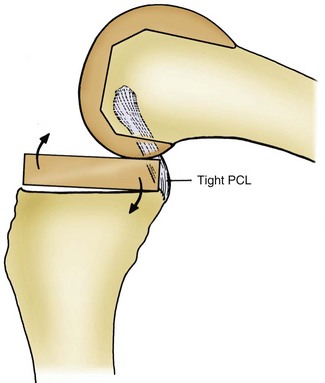
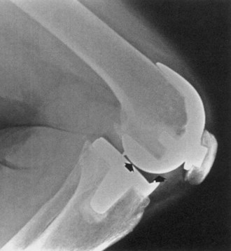
To function properly, the PCL must be accurately tensioned during knee replacement. If the PCL is too tight, this will promote excessive tibial roll-back, thereby impeding knee flexion, causing increased posterior stresses, and risking posterior polyethylene overload and anterior femoral component displacement. A tight PCL may also cause the knee to hinge “open like a book” (Fig. 105-25). Recognition of excess PCL tightness is possible by observing anterior tibial component “lift-off” with trial components (Fig. 105-26). Conversely, when the PCL is too loose, it does not control movement between the tibia and the femur (Fig. 105-27), allowing the femur to roll forward paradoxically (opposite of normal roll-back) in flexion, potentially limiting flexion by posterior impingement. The “slide-back” test has been described to assess for proper PCL tension following component positioning in rotating platform systems. The trial insert (without stabilizing post) is inserted and the knee flexed to 90 degrees. If the PCL is too tight, the insert moves posterior. Conversely, a PCL with excessive laxity will allow anterior migration of the insert. Best results have been reported with PCL tension adjusted to provide for 1 to 3 mm of posterior insert translation.184
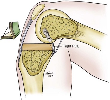
Figure 105-25 An overtight posterior cruciate ligament causes “booking.” Excessive roll-back of the femur occurs, and the knee hinges open.
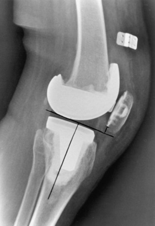
In practice, techniques that are aimed at preserving the PCL meet these requirements to varying degrees. The balance of the PCL remains a subjective assessment. Proper balancing even in the hands of experienced surgeons does not guarantee normal knee kinematics and tibial roll-back. A few systems mimic the medial slope of the normal tibia, and some cut the tibia at right angles to its shaft. However, all measured resection knee systems share the objective of closely preserving or restoring the anatomic joint line by referencing the distal femur. If this joint line preservation is achieved and the PCL is retained, the arc of motion should also be close to normal with correct ligament tensioning and optimal patellar tracking throughout the range of motion. Because patellofemoral dysfunction remains the cause of many unsatisfactory knee arthroplasties, maintenance of the anatomic joint line is potentially valuable. An optimal joint line avoids patella infera (Fig. 105-28). Further evidence comes from Figgie and colleagues,68 who demonstrated that if the patella is not within a defined sagittal neutral zone (10 to 30 mm above the joint line), a greater number of patellar problems are observed (Fig. 105-29).
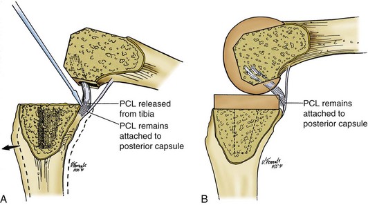
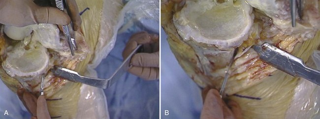
Successful PCL retention in TKA requires sustained function and proper initial balancing. Ligament balancing techniques have been developed that permit PCL retention when the ligament is contracted but remains competent.169,179,185 The technique is similar to the medial release performed for balancing varus deformity. A graduated PCL release (Fig. 105-30A) is performed from the posterior aspect of the tibia using a periosteal elevator until the PCL tension is deemed appropriate (see Fig. 105-30B). However, even for a skilled surgeon, it may be difficult to achieve the aims of successful PCL retention.38 Although the PCL is typically intact in most arthritic knees,183,186 the PCL can also degenerate and contract as part of the arthritic process,5,112 rendering the ligament nonfunctional and making PCL retention not applicable in some arthritic knee deformities.120,186 Likewise, the PCL occasionally becomes incompetent in the months or years after knee replacement, rendering the prosthesis unstable.155,212 Using cine-radiography, Dennis et al demonstrated paradoxical roll-forward of the femur on the tibia as the knee flexes in apparently well-functioning knees with a retained PCL.45 Follow-up studies by these investigators have reported improved and more consistent kinematics with an intact PCL when combined with an asymmetrical femoral component. More recent studies have even demonstrated reliable femoral roll-back with PCL retention in newer posterior stabilized designs.27,113
Anterior Cruciate Ligament
The anterior cruciate ligament (ACL) is an important functional element in the normal knee; its absence causes not only instability but an abnormal pattern of motion, including rotational and sliding movements (e.g., pivot shift). Together with the PCL, the ACL forms a “four-bar linkage”145 at the center of the knee, and the absence of either component destroys this mechanism. Abnormal sliding movements, in particular, can be expected when only the PCL is preserved.43,44,109,197 Cruciate retention refers only to the PCL in the context of TKA. The ACL is sacrificed in most modern bicondylar total knee systems. Only a few knee prostheses are designed to preserve both cruciate ligaments. The bi-cruciate retaining meniscal-bearing Oxford knee is not recommended unless both ligaments are present.78 In many arthritic knees, the ACL is damaged or absent, and most cruciate preserving systems advocate removal of the ACL.
Integrating the Measured Resection and Gap Techniques
From the previous discussion, it is apparent that philosophical differences exist between the gap balancing school of thought and the measured resection school of thought. The classic gap method emphasizes preservation of tibial bone and conforming joint surfaces, and accepts, when required, proximal migration of the joint surface to balance the gaps. The classic measured resection school of thought emphasizes preservation of the joint axis and accepts less congruence of the flexion and extension gaps. Flexion contractures, when present, are corrected by a combination of a posterior capsular release and stretching out of the remaining contracture with postoperative physiotherapy.199 In contrast, the gap technique emphasizes the distal femoral bone resection in combination with posterior capsulotomy and PCL resection to accomplish intraoperative correction of flexion contractures, a principle emphasized by Insall.
Despite obvious differences in philosophy, the distinctions between the gap and measured resection techniques have blurred with the evolution of surgical techniques. Methods of PCL recession or release have made the two techniques more similar. Because PCL release opens both flexion and extension gaps, measured resection used with PCL release creates larger gaps, especially in flexion.106 In a clinical study of PCL resection, Kadoya measured an increase in the medial and lateral flexion gaps of 4.8 mm and 4.5 mm, respectively, as compared with increases in the medial and lateral extension gaps of 0.9 mm and 0.8 mm, respectively. Using fluoroscopic analysis, several investigators have demonstrated that femoral roll-back does not occur with flexion in cruciate retaining prostheses.109,197 In fact, some authors report femoral roll-back similar to a natural knee using posterior stabilized prosthetic designs.43,44 Furthermore, flat tibial surfaces are not a prerequisite for PCL retention.185 In long-term follow-up evaluations of cruciate retaining knees with conforming articular surfaces, satisfactory results have been reported.172,186,214 Therefore, completely flat tibial surfaces for PCL retaining designs are not necessary, and cupping of some degree is acceptable (provided the PCL-driven roll-back is not overly constrained). If this degree of articular conformity is permissible and compatible with PCL retention, then a major objection (polyethylene wear) to retaining the PCL is negated.
Current Preference in Knee Balancing
The current preference in knee ligament balancing is a modified gap technique that has elements of both gap and measured resection methods. Insall advocated a blend of techniques whereby measured resections of both the distal femur and the proximal tibia are performed, avoiding the need for a variable distal femoral cut. Posterior referencing of the femoral condyles with some accommodation to a balanced flexion gap at the same time allows measured resection and balancing of the flexion gap as well. This measured resection combined with balancing of the flexion gap is facilitated by a larger inventory of femoral component sizes than existed when gap balancing was described, as well as a femoral component designed with a divergent anterior cut to minimize the risk of anterior femoral notching. Femoral component sizing and positioning remain critical to proper balancing. One should avoid allowing the femoral component to sit proud of the anterior femoral cortex, even to a minor degree (see Fig. 105-16). Because PCL release opens the flexion and extension gaps, modifications of the measured resection technique are possible. If the PCL is appropriately adjusted, strict adherence to anatomic alignment (varus tibial cut) is no longer required, and the classic alignment (perpendicular tibial cut) traditionally assigned to the gap technique can be applied. As noted previously, some degree of articular congruency that does not conflict with PCL kinematics is permissible, improving the prospects for longer-term polyethylene performance.
Summary of Modified Gap Technique
Tibia first technique is done as follows:
Preoperative Planning
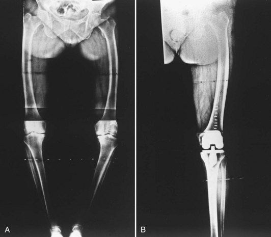
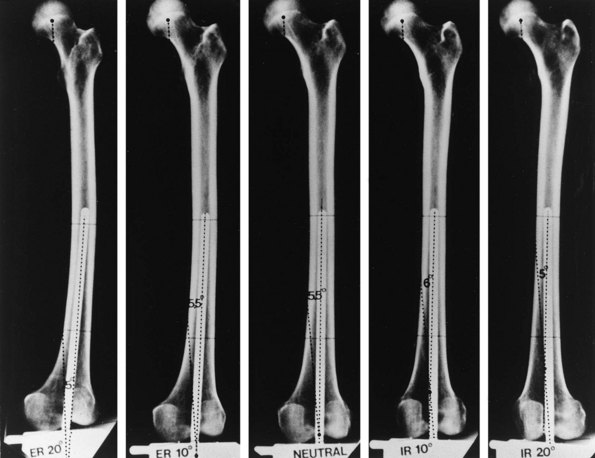
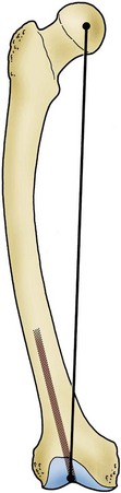
Full-length radiographs that show hip, knee, and ankle joints are desirable for preoperative planning but require special equipment. Standard radiographs showing the distal femoral and proximal tibial anatomic axis serve as an acceptable alternative to long films when there is no history of prior bone instrumentation or trauma, or clinical suspicion of excessive bowing. Radiographs are position sensitive, requiring care to obtain the films in neutral rotation (Figs. 105-31 and 105-32).102 Information concerning the angle of femoral and tibial cuts and the desired entry hole position (which may not be in the bone center) is obtained. Unusual shaft bowing is noted (Fig. 105-33). Unusual anatomic variations such as unusual canal size, angular malalignment, or previous surgery that could cause intraoperative difficulty are noted (Fig. 105-34).
Exposure
Routine Exposure
Techniques to Enhance Exposure in Standard Medial Parapatellar Approach
Difficult Exposures
Rectus Snip
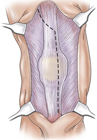
The rectus snip is the extensile proximal exposure described by Insall for the medial parapatellar approach.73 The snip is performed (Fig. 105-36) as needed after other methods of patellar mobilization already described have been employed. The medial incision for the quad snip is the same as that described for the standard midline approach. At the apex of the quadriceps tendon, the arthrotomy is continued laterally across the thin proximal portion of the tendon into the vastus lateralis, dividing the rectus tendon superficially and the trilaminar tendon extensions of the vastus muscles deeply. More distally, a lateral retinacular patellar release may also be done at this stage if it is determined that the lateral retinaculum is sufficiently tight so as to pull the patella laterally or restrict knee bending. The superior lateral genicular vessels need to be identified and isolated as they run at the lower border of the vastus lateralis muscle. These vessels can sometimes be saved when identified and protected during the lateral release. An important feature of this approach is that none of the structures contributing to knee extension are transversely divided.
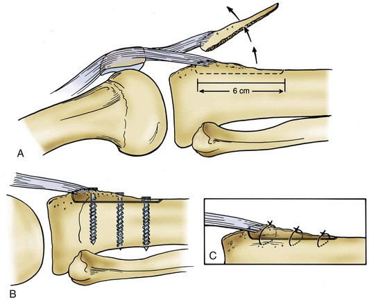
Tibial Tubercle Osteotomy
A tibial tubercle osteotomy can facilitate exposure of a stiff knee.219 This technique requires that the fragment of bone osteotomized should be sufficiently large to enhance the potential for later healing back to the tibia (Fig. 105-37). The tibial fragment is opened on a lateral soft tissue hinge. A tibial fragment of sufficient size may be securely reattached by wires or screws at the conclusion of the operation, whereas small fragments in osteoporotic bone afford insufficient substance for successful reattachment. Whiteside217 reported on use of this technique in 136 knees—both primary and revision TKAs. Complications were few, and no further release of the quadriceps mechanism was necessary in any procedure. However, Wolff and colleagues222 reported a 23% complication rate when using a similar technique.
Subperiosteal Peel
In ankylosed knees, it may be necessary to perform a subperiosteal exposure of the femur or tibia. It is advisable to begin with a subperiosteal exposure of the medial tibia to mid-diaphysis while attempting to flex and externally rotate the knee, being careful not to avulse the femoral attachment of the MCL. If medial peel is not successful in creating adequate motion, the periosteum of the lower femur is incised, and the lower femur can be partially skeletonized by subperiosteal dissection (Fig. 105-38). The soft tissue envelope is peeled from the bone as a continuous sleeve and is retracted posterior, allowing the distal femur to be buttonholed forward. This exposure, combined with medial subperiosteal dissection of the upper tibia, allows the knee to be flexed without danger of damaging or tearing important soft tissue structures, which are often very fragile in an ankylosed knee because of prolonged lack of movement and physiologic stress. When the incision is closed, the soft tissue envelope falls back around the bones. This technique is useful for long-standing ankylosis of the knee and for reimplantation after infection.141 Extensive exposures that result in medial-lateral instability patterns may occasionally require the use of increased articular constraint. The risk of extensive subperiosteal exposure is devascularization with subsequent osteonecrosis of the condyle. As such, extensive releases should be reserved for only the most extreme cases.
Closure
Closure should be anatomic, with effort made to restore the longitudinal alignment of the medial and lateral soft tissues along the incision. Tissues should be approximated without being excessively tightened or imbricated. Closure of the knee in 45 degrees of flexion or greater will help to align the capsular incision using the shape of the incision or a transverse ink or cautery mark as a guide to alignment.58,137 Insall routinely performed a modified vastus medialis obliquus (VMO) advancement, in which the medial soft tissue envelope is advanced several millimeters distal relative to the lateral soft tissues. Because the VMO is important in terminal extension, this advancement was meant to reduce the risk of a postoperative extension lag.
Techniques and Instrumentation
Cutting Blocks
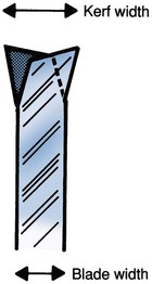
Bone cuts may be made from the free edge of the cutting block or through slotted capture guides. The slots may afford some degree of safety by limiting the excursion of saw blades; however, in practice they obscure the saw blade tip, potentially increasing the risk of compromising important structures such as the MCL, and sometimes leading to the creation of metal debris if the saw becomes confined. Although saw blades designed for the capture guides function well in the cutting slots, their cutting teeth are less efficient, because the teeth are designed with less offset to allow the blade to pass through the cutting slot (Fig. 105-39). When capture guides are used, it is important to lubricate surfaces and not to lever the saw blade against the guide to minimize the generation of metallic debris from the saw rubbing the cutting block. Milling frames are particularly useful in improving the accuracy of patellar preparation. Milling frames used in some systems to make the intercondylar cut create a smooth bone surface by their rotary blade action. Rotary blades have been shown to generate less heat than standard saw blades, thereby creating less damage to the cut bony surface.
Efficiency in femoral and tibial preparation has been advanced through improved instrumentation. Traditionally, multiple femoral cuts were made with individual cutting blocks. Newer universal cutting blocks allow multiple steps of bone surface preparation to be performed using a single block (Fig. 105-40). Most newer femoral cutting blocks provide slots for the anterior, posterior, and chamfer cuts, as well as guides for creation of the distal femoral lug holes. New technology has allowed introduction of cutting blocks prefabricated for an individual patient based on preoperative imaging and preplanned cuts. The accuracy, reliability, and economic feasibility of these designs are yet to be determined.
Alignment Guides
It is generally agreed that restoration of the mechanical axis of the limb should be achieved. Alignment is attained by making appropriate cuts on the femur and tibia, in addition to balancing the ligaments. Standard alignment guides may be placed according to external landmarks such as the anterosuperior iliac spine or the center of the hip joint166 proximally and the ankle mortise distally (Fig. 105-41). Because these landmarks can sometimes be hard to identify, intramedullary guides have become popular for making the distal femoral osteotomy, and extramedullary guides for the proximal tibial resection.
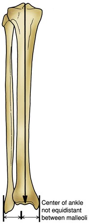
Figure 105-41 Center of the knee. Center of the talus axis lies a few millimeters medial to the center point between the malleoli.
Method of Alignment
Classic Method
Either the tibial or the femoral osteotomy may be performed first (Fig. 105-42). The valgus cut at the distal femur in theory is the difference between the anatomic and mechanical axes, created using the femoral shaft as the anatomic reference. The distal femoral valgus can be varied depending on the patient’s body habitus, generally falling around 5 to 6 degrees of valgus. Valgus knees are generally cut in 4 to 5 degrees of valgus, whereas varus and normally aligned knees are cut at 5 to 6 degrees of valgus. In obese patients, it is important to limit the amount of valgus to 5 degrees to avoid contact between the medial knee soft tissues. The tibial cut is always made neutral to the tibial anatomic axis.129 Hsu and associates91 confirmed that 7 degrees of femoral valgus matched with 0 degrees of proximal tibial alignment resulted in the most even load distribution across a total condylar knee prosthesis. Ample evidence suggests that a varus tibial cut not only results in uneven stress distribution in the proximal tibia79 but also leads to premature clinical failure.170
Anatomic Method
In an attempt to re-create natural knee kinematics with a PCL retaining prosthesis, Hungerford and Kenna used an anatomic method (Fig. 105-43) of lower limb alignment for TKA.93 Femoral valgus is set at an anatomic 9 to 10 degrees, and the tibial cut is made in 2 to 3 degrees of varus, thereby creating an anatomic 6 to 7 degrees of lower extremity valgus. Hsu and colleagues91 demonstrated that these angles produce even load distribution across the knee joint in a cruciate retaining design. As noted previously, if the surgeon is not experienced in this technique, intentional varus tibial cuts can easily result in excessive tibial varus, creating uneven load distribution and ligament imbalance.
Tibial Guides
Background
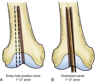
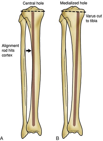
Most systems continue to use an extramedullary guide for the upper tibial osteotomy. Advocates of intramedullary tibial guides maintain that a rod of sufficient length reaching well into the tibial diaphysis will reliably align the tibial-cutting guide when there is no bow or offset to the tibial shaft. One potential pitfall of the intramedullary technique is that the shape of the tibia is inconsistent. Additionally, as for any intramedullary guide, the entry point is critical to alignment. Templating to determine the proper entry point for the tibial guide on the tibial surface will minimize the risk of creating a varus tibial cut based on a medial entry point and a bowed tibia. A central entry hole often will cause the intramedullary rod to impact against the tibial cortex (usually lateral), and placing the entry hole so that this does not happen alters the angle of the proximal guide (Fig. 105-44).
The extramedullary tibial guide is placed on the leg using surface landmarks. The distal end of the guide attaches above the ankle, while the proximal end is pinned to the center of the proximal tibia, generally at the medial one third of the tibial tubercle. Most guides allow adjustment at the ankle in both mediolateral and anteroposterior directions. The center of the ankle does not exactly correspond to the midpoint between the malleoli but instead is slightly medial to this point (5 to 10 mm) (see Fig. 105-41). The anteroposterior distal guide adjustment controls the posterior slope of the proximal tibial cut. The posterior slope of the proximal tibia may also be incorporated into the tibial osteotomy. As noted previously, we favor an essentially perpendicular cut relative to the tibial shaft. However, some systems, especially cruciate retaining designs and some mobile bearing knee designs, function more effectively with posterior slope. The 7 degrees of posterior slope is anatomic when the subchondral bone is considered, but when the posterior menisci are taken into consideration, the proximal tibial surface is actually perpendicular to the shaft (Fig. 105-45).
In obese patients, anteroposterior guide adjustment at the ankle may be necessary to make the guide parallel to the tibial shaft. Locating the proper proximal position of the extramedullary guide may be difficult; the natural tendency is to place the guide medially, producing a varus cut. Mobilization of the infrapatellar ligament combined with a lower profile lateral plateau cutting surface will facilitate placement of the tibial guide. By referencing off the tibial plateau center, the tibial shaft axis, and the center of the ankle, proper alignment for the proximal tibial osteotomy is usually possible. Several investigators have demonstrated that extramedullary and intramedullary systems are equally accurate in establishing tibial alignment.42,122 However, intramedullary instrumentation forfeits some of its accuracy in the face of tibial bowing or offset of the tibial shaft, especially when used for valgus knees. Simmons and coworkers192 noted that accuracy for intramedullary tibial alignment systems was 83% for varus knees versus 37% for valgus knees; they attributed the poor accuracy to tibial bowing observed in two thirds of valgus knees.
Related posts:
 Articular Cartilage: Biology, Biomechanics, and Healing Response
Advanced Technologies in Performing Total Knee Arthroplasty: Roundtable Discussion
In Vivo Mechanics and Vibration of the Knee Joint
Secondary, Spontaneous, and Postarthroscopy Osteonecrosis of the Knee: Diagnosis and Management
Advances in Mechanical Compression Devices
Articular Cartilage Injury and Adult OCD: Treatment Options and Decision Making
Articular Cartilage: Biology, Biomechanics, and Healing Response
Advanced Technologies in Performing Total Knee Arthroplasty: Roundtable Discussion
In Vivo Mechanics and Vibration of the Knee Joint
Secondary, Spontaneous, and Postarthroscopy Osteonecrosis of the Knee: Diagnosis and Management
Advances in Mechanical Compression Devices
Articular Cartilage Injury and Adult OCD: Treatment Options and Decision Making
Stay updated, free articles. Join our Telegram channel

Full access? Get Clinical Tree


